PICOe-9452 User Manual
PICOe-9452 User Manual
PICOe-9452 User Manual
Create successful ePaper yourself
Turn your PDF publications into a flip-book with our unique Google optimized e-Paper software.
<strong>PICOe</strong>-<strong>9452</strong> Half-size CPU Card<br />
List of Figures<br />
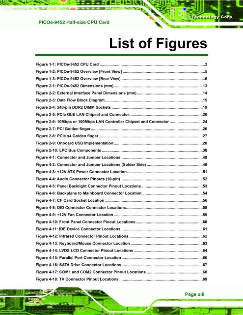
Figure 1-1: <strong>PICOe</strong>-<strong>9452</strong> CPU Card ................................................................................................3<br />
Figure 1-2: <strong>PICOe</strong>-<strong>9452</strong> Overview [Front View] ...........................................................................5<br />
Figure 1-3: <strong>PICOe</strong>-<strong>9452</strong> Overview [Rear View].............................................................................6<br />
Figure 2-1: <strong>PICOe</strong>-<strong>9452</strong> Dimensions (mm).................................................................................13<br />
Figure 2-2: External Interface Panel Dimensions (mm)............................................................14<br />
Figure 2-3: Data Flow Block Diagram .........................................................................................15<br />
Figure 2-4: 240-pin DDR2 DIMM Sockets ...................................................................................19<br />
Figure 2-5: PCIe GbE LAN Chipset and Connector...................................................................20<br />
Figure 2-6: 10Mbps or 100Mbps LAN Controller Chipset and Connector ..............................24<br />
Figure 2-7: PCI Golden finger......................................................................................................26<br />
Figure 2-8: PCIe x4 Golden finger...............................................................................................27<br />
Figure 2-9: Onboard USB Implementation .................................................................................28<br />
Figure 2-10: LPC Bus Components ............................................................................................30<br />
Figure 4-1: Connector and Jumper Locations...........................................................................48<br />
Figure 4-2: Connector and Jumper Locations (Solder Side) ...................................................49<br />
Figure 4-3: +12V ATX Power Connector Location.....................................................................51<br />
Figure 4-4: Audio Connector Pinouts (10-pin)...........................................................................52<br />
Figure 4-5: Panel Backlight Connector Pinout Locations........................................................53<br />
Figure 4-6: Backplane to Mainboard Connector Location .......................................................54<br />
Figure 4-7: CF Card Socket Location .........................................................................................56<br />
Figure 4-8: DIO Connector Connector Locations......................................................................58<br />
Figure 4-9: +12V Fan Connector Location .................................................................................59<br />
Figure 4-10: Front Panel Connector Pinout Locations.............................................................60<br />
Figure 4-11: IDE Device Connector Locations...........................................................................61<br />
Figure 4-12: Infrared Connector Pinout Locations ...................................................................62<br />
Figure 4-13: Keyboard/Mouse Connector Location ..................................................................63<br />
Figure 4-14: LVDS LCD Connector Pinout Locations ...............................................................64<br />
Figure 4-15: Parallel Port Connector Location ..........................................................................66<br />
Figure 4-16: SATA Drive Connector Locations..........................................................................67<br />
Figure 4-17: COM1 and COM2 Connector Pinout Locations ...................................................68<br />
Figure 4-18: TV Connector Pinout Locations ............................................................................69<br />
Page xiii


