PICOe-9452 User Manual
PICOe-9452 User Manual
PICOe-9452 User Manual

You also want an ePaper? Increase the reach of your titles
YUMPU automatically turns print PDFs into web optimized ePapers that Google loves.
<strong>PICOe</strong>-<strong>9452</strong> Half-size CPU Card<br />
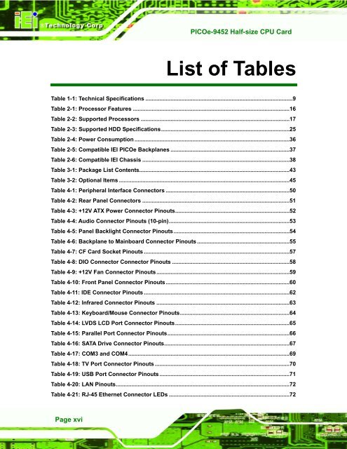
List of Tables<br />
Table 1-1: Technical Specifications ..............................................................................................9<br />
Table 2-1: Processor Features ....................................................................................................16<br />
Table 2-2: Supported Processors ...............................................................................................17<br />
Table 2-3: Supported HDD Specifications..................................................................................25<br />
Table 2-4: Power Consumption ...................................................................................................36<br />
Table 2-5: Compatible IEI <strong>PICOe</strong> Backplanes ............................................................................37<br />
Table 2-6: Compatible IEI Chassis ..............................................................................................38<br />
Table 3-1: Package List Contents................................................................................................43<br />
Table 3-2: Optional Items .............................................................................................................45<br />
Table 4-1: Peripheral Interface Connectors ...............................................................................50<br />
Table 4-2: Rear Panel Connectors ..............................................................................................51<br />
Table 4-3: +12V ATX Power Connector Pinouts.........................................................................52<br />
Table 4-4: Audio Connector Pinouts (10-pin).............................................................................53<br />
Table 4-5: Panel Backlight Connector Pinouts ..........................................................................54<br />
Table 4-6: Backplane to Mainboard Connector Pinouts ...........................................................55<br />
Table 4-7: CF Card Socket Pinouts .............................................................................................57<br />
Table 4-8: DIO Connector Connector Pinouts ...........................................................................58<br />
Table 4-9: +12V Fan Connector Pinouts.....................................................................................59<br />
Table 4-10: Front Panel Connector Pinouts ...............................................................................60<br />
Table 4-11: IDE Connector Pinouts .............................................................................................62<br />
Table 4-12: Infrared Connector Pinouts .....................................................................................63<br />
Table 4-13: Keyboard/Mouse Connector Pinouts......................................................................64<br />
Table 4-14: LVDS LCD Port Connector Pinouts.........................................................................65<br />
Table 4-15: Parallel Port Connector Pinouts..............................................................................66<br />
Table 4-16: SATA Drive Connector Pinouts................................................................................67<br />
Table 4-17: COM3 and COM4.......................................................................................................69<br />
Table 4-18: TV Port Connector Pinouts ......................................................................................70<br />
Table 4-19: USB Port Connector Pinouts ...................................................................................71<br />
Table 4-20: LAN Pinouts...............................................................................................................72<br />
Table 4-21: RJ-45 Ethernet Connector LEDs .............................................................................72<br />
Page xvi