

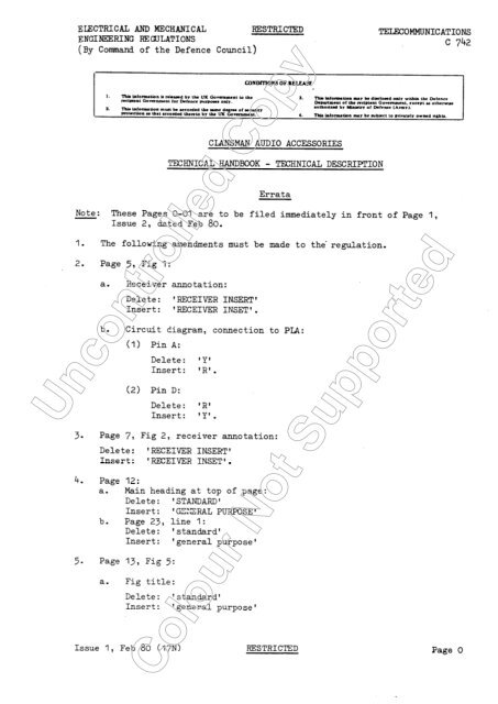
Uncontrolled Copy C olour N ot Supported
Uncontrolled Copy C olour N ot Supported
Uncontrolled Copy C olour N ot Supported

You also want an ePaper? Increase the reach of your titles
YUMPU automatically turns print PDFs into web optimized ePapers that Google loves.
ELECTRICAL AND MECHANICAL<br />
ENGINEERING REGULATIONS<br />
(By Command of the Defence<br />
Council)<br />
RESTRICTED<br />
TELECOMMUNICATIONS<br />
C 742<br />
CLANSMAN AUDIO ACCESSORIES<br />
TECHNICAL HANDBOOK - TECHNICAL DESCRIPTION<br />
Errata<br />
N<strong>ot</strong>e: These Pages O-01 are to be filed immediately in front of Page 1,<br />
Issue 2, dated Feb 80.<br />
I.<br />
2.<br />
The following<br />
Page 5, Fig 1:<br />
amendments must be made to the* regulation.<br />
a. Receiver ann<strong>ot</strong>ation:<br />
Delete: 'RECEIVER INSERT'<br />
Insert: 'RECEIVER INSET'.<br />
b. Circuit diagram, connection to PLA:<br />
(1) Pin A:<br />
Delete: 'Y'<br />
Insert: 'R'.<br />
(2) Pin D:<br />
Delete: 'R'<br />
Insert: 'Y' .<br />
3.<br />
4.<br />
5.<br />
Page 7, Fig 2, receiver ann<strong>ot</strong>ation:<br />
Delete: 'RECEIVER INSERT'<br />
Insert: 'RECEIVER INSET'.<br />
Page 12:<br />
a. Main heading at top of page:<br />
Delete: ' STANDARD '<br />
Insert: 'GEXRAL PURPOSE'<br />
b. Page 23, line 1:<br />
Delete: 'standard1<br />
Insert: 'general purpose'<br />
Page 13, Fig 5:<br />
a. Fig title:<br />
Delete: 'standard'<br />
Insert: 'general purpose'<br />
Issue 1, Feb 80 (17N) RESTRICTED Page 0
TELECOMMUNICATIONS RESTRICTED ELECTRICAL AND MRWA!KtCAL<br />
C 742 ENGINEERING RXGULATIONS<br />
b. Microphone ann<strong>ot</strong>ation:<br />
Delete: 'MICROPHONE INSERT'<br />
Insert: 'MICROPHONE INSET'.<br />
C. Receiver ann<strong>ot</strong>ation:<br />
Delete: 'RECEIVER INSERT'<br />
Insert: 'RECEIVER INSET'.<br />
6.<br />
7.<br />
Page 14, para 27, line 1:<br />
Delete: 'standard'<br />
Insert: 'general purpose'.<br />
Page 15, Fig 6:<br />
a. Microphone ann<strong>ot</strong>ation:<br />
Delete: 'MICROPHONE INSERT'<br />
Insert: 'MICROPHONE INSET'.<br />
b. Receiver ann<strong>ot</strong>ation:<br />
Delete: 'RECEIVER INSERT'<br />
Insert: 'RECEIVIZR INSET'.<br />
8.<br />
9.<br />
Page 16, para 34, line 1:<br />
Delete: 'standard'<br />
Insert: 'general purpose'.<br />
Page 17, Fig 7:<br />
a. Microphone ann<strong>ot</strong>ation:<br />
Delete: 'MICROPHONE INSERT'<br />
Insert: 'MICROPHONE INSET'.<br />
b. Receiver ann<strong>ot</strong>ation:<br />
Delete: 'RECEIVl3R INSERT'<br />
Insert: 'RHCEIVER INSET'.<br />
10.<br />
11.<br />
Page 19, Fig 8, receiver ann<strong>ot</strong>ation:<br />
Delete: 'RECEIVER INSERT'<br />
Insert: 'RFCEIVER INSET'.<br />
Page 20:<br />
Delete: ‘2896/Tels’ and 'END'.<br />
Page 01 RESTRICTED Issue 1, Feb 80
ELECTRICAL AND MECHANICAL<br />
ENGINEERING REGULATIONS<br />
(By Command of the Defence<br />
Council)<br />
KFSTRICTED<br />
TEIXCOMMU-NICATIONS<br />
C 742<br />
I CONDITIONS OF DELkXSE<br />
CMSMAN AUDIO ACCESSORIES<br />
TECHNICAL HANDBOOK - TECHNICAL DESCRIPTION<br />
These Pages I-4 supersede Pages I-4, Issue 1, dated Aug 73.<br />
CONTENTS<br />
INTRODUCTION<br />
GENERAL ....................................<br />
EI;ECTRICAL PARM$llERS ..............................<br />
MECHANICAL PARAMmERS ..............................<br />
TESTING AND REPAIR FACIIJTIXS ........................<br />
Para<br />
:<br />
4<br />
5<br />
HELMET-HEADSET, EIECTRICAL, 'A' VEHICLE CREWMAN'S HEADGEAR<br />
ROLE AND PURPOSE ................................. 6<br />
CONSTRUCTION ................................. 7<br />
DESCRIPTION ................................. 10<br />
BEADSET MICROPHONE, 'A'<br />
VEEICIE STAFF USERS HEADGEAR (AVSU)<br />
ROI;F; AJD PURPOSE ................................. 12<br />
CONSTRUCTION ................................. '13<br />
DESCRIPTION .................................... 16<br />
BEADSET MICROPHONE, 'B' VEHICIZ AND INFANTRY (BV and I><br />
ROLE AND PURPOSE ................................. 17<br />
ZONSTRUCTION ................................. 18<br />
DESCRIF'IJION .................................... 19<br />
CABLE ASSEMBLY, SWITCH ELECTRICAL<br />
ROI;E AND PTJRFQSE .................................<br />
CONSTRUCTION .................................<br />
DESCRIPTION ..................................<br />
20<br />
21<br />
22<br />
HANDSET, GENERALPURPOSE<br />
ROLE AND PURPOSE ................................. 23<br />
CONSTRJCTION ................................. 24<br />
DESCRIPTION .................................... 25<br />
Issue 2, Feb 80 (17N) RESTRICTED Page I
TELECOMMUNICATIONS<br />
C 742<br />
RESTRICTED<br />
EIECTRICAL AND MECHANICAL<br />
ENGINEERING RXGULATIONS<br />
Para<br />
HANDSET, REMOTE CONTROL<br />
ROLE AND PURPOSE . . .<br />
CONSTRUCTION . . .<br />
DESCRlPTION . . .<br />
. . .<br />
. . .<br />
. . .<br />
... ... ... ... ... ...<br />
... ... ... ... ... ...<br />
... ... ... ... ... ...<br />
. . .<br />
. . .<br />
. . .<br />
. . .<br />
. . .<br />
m..<br />
. . . .<br />
. . .<br />
. . .<br />
26<br />
27<br />
29<br />
HANDSET, TANK TEIEPH0N.H<br />
ROLE AND PURPOSE<br />
CONSTRUCTION .-.<br />
DESCRIPTION 0..<br />
. . .<br />
. . .<br />
. . .<br />
... ... ... ... ... ...<br />
... ... ... ... ... ...<br />
... ... ... ... ... ...<br />
. . .<br />
. . .<br />
. . .<br />
. . .<br />
. . .<br />
. . .<br />
. . .<br />
. . .<br />
. . .<br />
33<br />
34<br />
35<br />
SINGLF TRANSDUCER HEADGEAR ASSEMHLY<br />
ROLF: AND PURPOSE 0.0<br />
CONSTRUCTION 0..<br />
DESCRIPTION . . .<br />
... ... ... ... ... ... ...<br />
... ... ... ... ... ... ...<br />
... ... ... ... ... ... ...<br />
. . .<br />
. . .<br />
. . .<br />
. . .<br />
. . .<br />
. . .<br />
. . .<br />
. . .<br />
. . .<br />
;i<br />
39<br />
RESPIRATOR MICROPHONE<br />
ROLE AND PURPOSE . . .<br />
CONSTRUCTION . . .<br />
DESCRIPTION . . .<br />
... ... ... ... ... ... ...<br />
... ... ... ... ... ... ...<br />
... ... ... ... ... ... ...<br />
. . .<br />
. . .<br />
. . .<br />
. . .<br />
. . .<br />
. . .<br />
. . .<br />
. . .<br />
. . .<br />
40<br />
41<br />
42<br />
HHADSET MICROPHONE UK/PRC 349<br />
ROLE AND PURPOSE 0..<br />
CONSTRUCTION 0..<br />
DESCRIPTION . . .<br />
... ... ... ... ... ... ...<br />
... ... ... ... ... ... ...<br />
... ....... ... ... ... ...<br />
. . .<br />
. . .<br />
. . .<br />
. . .<br />
. . .<br />
. . .<br />
. . .<br />
. . .<br />
. . .<br />
43<br />
44<br />
45<br />
Fig<br />
FIGURES<br />
Page<br />
1 Helmet-headset electrical, 'A' vehicle crewman's headgear<br />
Headset microphone (AVSU) .....................<br />
: Headset microphone (BV and I) ..................<br />
4 Cable assembly, switch electrical ...............<br />
Handset, general purpose .....................<br />
2 Handset, rem<strong>ot</strong>e control .....................<br />
Handset, tank telephone .....................<br />
r3 Single transducer, headgear assembly ............<br />
9 Respirator microphone .....................<br />
10 Headset, microphone UK/PRC 349 ..................<br />
. . .<br />
. . .<br />
. . .<br />
. . .<br />
. . .<br />
. . .<br />
. . .<br />
. . .<br />
. . .<br />
. . .<br />
5<br />
;<br />
11<br />
13<br />
'15<br />
17<br />
19<br />
sz<br />
Page 2 RESTRICTED Issue 2, Feb 80
ELEYCTRICAL AND MECHANICAL UK RESTRICTED TELECOMMONICATIONS<br />
ENGINEERING REGULATIONS C 742<br />
INTRODUCTION<br />
N<strong>ot</strong>e...<br />
These<br />
5 has<br />
Pages 3-4, Issue 3 supersede Pages 3-4, Issue 2 dated Feb 80. P=a<br />
been amended.<br />
GENERAL<br />
1. The<br />
a.<br />
b.<br />
C.<br />
d.<br />
e.<br />
f.<br />
g-<br />
h.<br />
j.<br />
k.<br />
Clansman audio accessories consist of the following items:<br />
5965-99-620-3251 Helmet-headset, Electrical, 'A' Vehicle<br />
Crewmans Headgear.<br />
5965-99-620-5668 Headset Microphone (AVSU).<br />
5965-99-620-8320 Headset Microphone (HV and I>.<br />
5965-99-620-5667 Cable Assembly, Switch Electrical.<br />
5965-99-620-5669 Handset, General Purpose.<br />
5965-99-620-5670 Handset, Rem<strong>ot</strong>e Control.<br />
5965-g+620-5672 Handset, Tank Telephone.<br />
5965-99-622-5436 Single Transducer Headgear Assembly.<br />
5965-99-622-5437 Respirator Microphone.<br />
5965-99-643-7935 Headset Microphone, UK/PRC 349.<br />
2. With the exception of the electrical and mechanical parameters, and<br />
testing and repair facilities, this regulation describes each audio accessory<br />
seperately and is therefore, sectionslized in the order shown in Para I.<br />
ELECTRICAL PARAMETERS<br />
3. Microphone impedance: 300 + 60 8 with 10 mV at 1 kHz connected across<br />
the Microphone.<br />
Receiver impedance: 300 + 60 Q at 1 kHz.<br />
Power supply (Rem<strong>ot</strong>e<br />
HandsetandTank<br />
Telephone Handset): 18 V to 32 V d.c.<br />
MECHANICALPARAMETERS<br />
4. The lightweight microphone insets are of the pressure gradient (noise<br />
cacelling) type, whilst the receiver insets use smell rocking armatures.<br />
Cable connections within the audio accessories are terminated by push on<br />
connectors.<br />
TESTING AND REPAIR FACILITIES<br />
5. Failure diagnosis can be carried out using the Test Set, Audio Radio<br />
Accessories or a multimeter, whilst functional testing is achieved by<br />
connecting the headgear to a known good radio set or control harness, or by<br />
using the Test Set, Audio Radio Accessories.<br />
Issue 3, Jan 84 (ITN) UK RESTRICTED Page 3
TELECOMMUNICATIONS UKRESTRICTE33 ELECTRICAL AND MECHANICAL<br />
C 742 ENGlINEZXING REGUWITIONS<br />
I-ELMEZ-<br />
HEADSET ELECTRICAL, 'A' VEHICLE CREWMANS HEADGEAR (Fig I><br />
ROLE AND PURPOSE<br />
6. The Helmet - Headset Electrical, 'A' Vehicle Crewtnans Headgear is<br />
designed for use in AFV installations fitted with Larkspur II or Clansman<br />
radio control harness. The headgear provides hands free microphone operation,<br />
pr<strong>ot</strong>ection against and exclusion of ambient noise and bump pr<strong>ot</strong>ection for the<br />
head.<br />
CONSTRUCTION<br />
7. The receiver insets are mounted in foam padded ear defenders. The ear<br />
defenders are fitted with adjustable accoustic valves which provide<br />
pr<strong>ot</strong>ection against external noise when closed, whilst allowing normal<br />
conversation when open. The receiver assemblies can be adjusted for vertical<br />
positioning over the ears.<br />
8. The microphone and boom assembly is attached to the right hand side of<br />
the helmet. The assembly incorporates a socket for the respirator microphone<br />
which, when connected, automatically inhibits the boom microphone. The boom<br />
is piv<strong>ot</strong>ed to permit positioning of the microphone to suit the users requirements<br />
and may be locked in the optimum position.<br />
9. An internal cats cradle and detachable foam pads fitted to the browline<br />
and neckline provide adjustments which allow each helmet to be fitted to suit<br />
the individual wearer.<br />
DESCRIPTION<br />
10. In normal use, the headgear is connected, via the Cable Assembly, Switch<br />
Electrical, to either a harness box or radio. The two receivers are<br />
independently wired, the left hand receiver being connected between pins D<br />
and E of plug PLA and the right hand receiver between pins G and E.<br />
Il. The boom microphone circuit includes the series resistor RI, the output<br />
being taken from pins A and B of plug PLA. When the respirator microphone<br />
(Fig 9) is connected to socket SKA, pins B and C are shorted together<br />
thereby inhibiting the boom microphone. The respirator microphone is<br />
connected between pins A and B with resistor RI connected in parallel.<br />
Page 4 UK RESTRICTED Issue 3, Jan 84
l!LExTRIcALANDMEcRAN1cAIl REElYRICTED !PEIXCOMMUNICATI~NS<br />
ENGIlllEERING REXXUTIONS C 742<br />
Kate: These Pages 5-6 supersede Pages 5-6, Igsue l.dated Aug 73. Fig I has<br />
been revised.<br />
SHELL<br />
VELCRO<br />
RETAINER<br />
CABLE<br />
(3 OFF)<br />
INNER CROWN PAD<br />
INTERNAL<br />
CABLE<br />
ACOUSTIC<br />
DAMPER<br />
LOCKING<br />
NUT<br />
EARSHELL ASSY (L .H)<br />
SELF ADHESIVE<br />
RUBBER PAD<br />
BOOM<br />
ASSY<br />
BASE<br />
RECEIVER<br />
INSERT<br />
VELCRO STRAP IRH)<br />
RESPIRATOR MICROPHONE<br />
SOCKET SKA<br />
MAIN CABLE ASSY-<br />
CABLE ENTRY<br />
HOUSING<br />
CHINSTRAP<br />
SKA<br />
VIEW ON REAR<br />
R.H SIDE<br />
w<br />
I<br />
L<br />
MC AND BOOM ASSY<br />
----s-v -I<br />
VIEW ON FRONT<br />
OF PLA<br />
SNATCH<br />
CONNECTOR<br />
PLA<br />
2896119<br />
VIEW ON FRONT<br />
OF SKA<br />
Fig 1 - Helmet, headset electrical, 'A' vehicle crewman's headgear.<br />
Issue 2, Sep 79 (17N) RESTRICTED Page 5
TELJ3COMMlJNICATIONS<br />
C-742<br />
ROLE AND PURPOSE<br />
RELSTRICTED<br />
HEADSEI' MICROPHONE (AVSU)<br />
ZUXTRICAL AND MECHANICAL<br />
ENGINEERING RETJULATIONS<br />
12. The headset microphone (AVSU) is designed for<br />
by personnel <strong>ot</strong>her than crewmen.<br />
use in AFV installations<br />
CONSTRUCTION<br />
13. The headset consists of two receiver assemblies with a microphone and<br />
boom assembly attached to the right-hand receiver.<br />
14. The receiver insets are mounted in foam padded ear defenders fitted<br />
with variable acoustic valves. A socket for the respirator microphone is<br />
fitted to the right-hand earshell assembly. The boom is piv<strong>ot</strong>ed to allow<br />
positioning of the microphone and may be locked in the optimum operating<br />
position.<br />
15. Adjustable straps and padded bands assist in fitting the headset to<br />
the individual wearer.<br />
DEXXIPTION<br />
16. The headset is normally connected to a harness box or radio via the<br />
cable assembly, switch electrical. The headset microphone (AVSU) is<br />
electrically identical to the helmet-headset (paras IO to 11 refer).<br />
Page 6 STRICTED Issue 2, Sep 79
33.XCTiUCAL AND l@XXANICAL<br />
ENGDlDZRR?G FBGUUTIONS<br />
ElEsTRlCTgD<br />
TKLBCOMMJNICATIORS<br />
c 742<br />
MICROPHONE<br />
y--~sTRAp<br />
I<br />
ACOUSTIC DAMPING PADS<br />
KNURLED<br />
LOCKING NUT -<br />
J f;l 7Jj--- RECEIVER INSERT<br />
ACOUSTIC<br />
VALVE<br />
\ RESPIRATOR MICROPHONE<br />
‘
TELEGOMKJNICATIONS<br />
c 742<br />
RESTRICTED<br />
ELECTRICAL AND MECHANICAL<br />
ENGlINEEEING RF&lLATIONS<br />
HEADSET MICROPHONE (BV AND I)<br />
ROLEANDPURPOSE<br />
17. The headset microphone (BV and I) is designed for use with infantry<br />
operated radios which may be man-pack or vehicle mounted.<br />
CONSTRUCTION<br />
18. The headgear is of lightweight moulded plastic construction. The<br />
earshells are foam padded for user's comfort. The microphone and boom<br />
assembly, respirator socket and cable assembly -are all m,ounted on the lefthand<br />
earpiece assembly, whilst the right-hand earphone assembly is detachable<br />
from the earpiece and designed as a *throw-away' item.<br />
DEXCRIPTION<br />
The headset microphone (EV and I) is electrically identical to the<br />
iz; vehicle crewman's headgear described in para 10, except for the<br />
electrical contacts of the right-hand earphone assembly. These comprise<br />
two brass studs which engage with two brass springs in the earshell assembly,<br />
the earphone assembly being retained and secured in position by a clip and<br />
strap.<br />
?age 8 REzrR1cTED Issue 1, Aug 73
ELECIXICALANDME~ICAL RESTRICTED TELECQMMUNICATIONS<br />
ENGINEERING REGULATIONS C 742<br />
N<strong>ot</strong>e...<br />
These Pages 9-10, Issue 2 supersede Pages g-10, Issue 1 dated Aug 73.<br />
The information has been updated.<br />
HEAOSTRAP<br />
ASSEMBLY<br />
(L.H.)<br />
INTED CIRCUIT 90ARD<br />
R.H. RECEIVER<br />
INSET<br />
R.H. EARSHELL<br />
NOTE POSITION<br />
OF CAM<br />
+I++~, i L.H. ’<br />
VIEW ON FRONT<br />
Of PlA<br />
A0<br />
80 OC<br />
VIEW ON FRONT<br />
ON<br />
5KA<br />
2896/132<br />
Fig 3 - Headset microphone (BV and I)<br />
Issue 2, Aug 82 (17N) RESTRICTED Page 9
TELECOMMUNICATIONS<br />
C 742<br />
RESTRICTED ELECTRICALAND MECHANICAL<br />
ENGINEERING REGULATIONS<br />
CABLE ASSEMBLY, SWITCH ELECTRICAL<br />
ROLE AND PURPOSE<br />
20. The cable assembly, switch electrical is used to connect the appropriate<br />
Clansman headgear to the harness, radio or associated equipment. The pressel<br />
switch for the headgear is contained in the pressel box.<br />
CONSTRUCTION<br />
21. The box comprises a lever operated pressel switch contained in a<br />
rectangular plastic moulded case. A spring clip, fixed to the case, allows the<br />
box to be clipped to the operators cl<strong>ot</strong>hing. The coiled cable is fixed to<br />
the box through a sleeve and gland nut, whilst a strain cord secured inside<br />
the box prevents the cable being pulled through the sleeve. Connections<br />
inside the pressel box are made by push-on connectors. A %-way socket is<br />
fixed to the main assembly and pr<strong>ot</strong>rudes through the pressel box cover where<br />
it is secured by a hexagonal nut. A pre-set Live Mic switch, operated by a<br />
sl<strong>ot</strong>ted-head screw, can be set to provide 'hands-free' operation when the<br />
cable assembly, switch electrical is connected to a harness box with LIVE IC<br />
facility.<br />
DESCRIPTION<br />
22. Items of Clansman headgear are connected to the cable assembly, switch<br />
electrical, which in turn is connected to a harness box, radio, or audio<br />
equipment at sockets labelled AUDIO or HEADGEAR. When used with the control<br />
harness, the cable assembly, switch electrical can be by-passed by the<br />
selection of LIVE IC (see Tels L 802, Table 6).<br />
Page 10 RESTRICTED Issue 2, Aug 82
ELECTRICAL AND MECHANICAL<br />
ENGINEEXING REGULATIONS<br />
TELECOMKUIiICATIORS<br />
c 742<br />
CONNECTOR AND<br />
LEAD ASSEMBLY<br />
PRESSEL<br />
S2 CONTACTS BAR ASSEMBLY<br />
LIVE MIC<br />
\ r/<br />
ACTUATING SCREW<br />
I<br />
I<br />
HEXAGONAL<br />
SECURING<br />
I<br />
NUT<br />
KNURLED<br />
SECURING<br />
NUT<br />
SCR;EN<br />
STRAI; CORD Pi?ESSEL SWITCH<br />
ANCHOR POINT ASSEMBLY Sl<br />
COVER<br />
PLUG<br />
PLA<br />
PLA<br />
A *-(-<br />
I<br />
I<br />
R<br />
LL<br />
WA<br />
I<br />
I<br />
SKA<br />
VIEW ON FRONT<br />
OF PLA<br />
I<br />
I<br />
F --(-<br />
BK<br />
II<br />
SlB<br />
I<br />
VIEW ON FRONT<br />
OF SKA<br />
2896/22<br />
RED 2:l<br />
fig 4 - Cable assembly, switch electrical<br />
Issue 1,Aug 73 RFJsTR1cTED Page 11
TJZLFCOMMUNICATICNS<br />
c 742<br />
RExxrR1cTED<br />
ELEXXRICAL AND MECHANICAL<br />
ENGllEEZING REClJLATIONS<br />
RANDSFT,STANDARD<br />
ROLEANDPURPOSR<br />
23. The handset, standard is a conventional hand-held telephone type handset<br />
used to operate individual radios.<br />
CONSTRUCTION<br />
24. The handset comprises a black plastic body containing microphone and<br />
receiver insets, a pressel switch and a p.c.b. assembly. All wiring connections<br />
are made on the p.c.b. which is accessible by removal of a cover<br />
plate. The pressel switch is operated by a lever which is recessed into<br />
the body to give a measure of pr<strong>ot</strong>ection against-accidental operation. A<br />
cl<strong>ot</strong>hing clip is secured to the handset body. Connections to the handset<br />
are made by a cable assembly which is passed through the cable entry plate<br />
and secured by a sheath and gland nut. A strain cord is secured inside the<br />
handset body.<br />
DESCRIPTION<br />
25. The receiver inset is permanently connected into circuit at pins D and<br />
E of plug PLA, whilst the microphone inset is connected into circuit by one<br />
pole of the pressel switch. The remaining pole of the pressel switch is<br />
used to connect pins E and F together and activate the transmit function in<br />
the radio.<br />
Page 12 RESTRICTED Issue 1, Aug 73
ELBCTRICALAND-ICAL<br />
I4TGINEERING RERJLATIONS<br />
RESTRICTED<br />
Txzac~IcATxoHs<br />
c 742<br />
STRAIN<br />
ANCHOR<br />
\<br />
SB<br />
SA<br />
- -<br />
3 - -<br />
PRESSEL<br />
BAR<br />
1<br />
SWITCH /<br />
ASSEMBLY<br />
CABLE<br />
PLATE<br />
ENTRY<br />
CABLE<br />
ASSEMBLY+/<br />
TOR<br />
ETNEC<br />
PLA<br />
B-<br />
I<br />
G<br />
I<br />
i<br />
VIEW ON FRONT<br />
OF PLA<br />
2896123<br />
2: I REDUCTION<br />
fig 5 - Handset standard<br />
I&sue 1, Aug 73 page 13
TELECOMMUNICATIONS<br />
c742<br />
RESTRICTED<br />
E;LBcTRICALAND~ICAL<br />
EKG-G RECULU‘IONS<br />
HANDSET, I3iExYm CONTROL<br />
26. The handset, rem<strong>ot</strong>e control enables a Clansman radio to be rem<strong>ot</strong>ely<br />
operated up to a distance of 3 Ian using DlO or 5 km using one pair of CTlO.<br />
CONSTRUCTION<br />
27. The handset is of similar construction to the handset, standard with the<br />
addition of a call switch and a thin film amplifier which, together with its<br />
associated components, is mounted on a p.c.b.<br />
28. The call switch and two insulation piecing cable connectors are mounted<br />
on the connector plate assembly. A cl<strong>ot</strong>hing clip is secured to the handset<br />
body.<br />
DESCRIPTION<br />
29. The rem<strong>ot</strong>e handset is connected to the rem<strong>ot</strong>e terminals of the apprcpriate<br />
Clansman harness box or radio by a 2-wire field cable, connection<br />
being made by the two insulation piercing connectors on the body of the handset.<br />
30. With the handset connected correctly to the harness or radio, a +ve<br />
voltage is applied to pins 9, 10 of module Xl and to the 27V zenor diode Dl.<br />
Under normal circumstances, Dl does n<strong>ot</strong> conduct and the current flow in the<br />
rem<strong>ot</strong>e loop is governed by the output impedance of module Xl. This impedance<br />
maintains the Clansman radio in the receive condition. Should the rem<strong>ot</strong>e<br />
lines be incorrectly connected, Dl conducts and the current flow in the rem<strong>ot</strong>e<br />
loop exceeds 15mA. This current represents the 'call* condition and the<br />
Clansman equipment produces the 2Mz call tone.<br />
31. To transmit, the pressel switch SA is operated thereby connecting the<br />
microphone across the amplifier input. The impedance presented by the handset<br />
produces a current of from 8-l%n~ to the Clansman equipment, which<br />
represents the transmit condition. Audio signals from the microphone are<br />
amplified and passed to line, and the earphone connected across the line<br />
connectors provides sidetone for the rem<strong>ot</strong>e operator.<br />
32. Operation of the CALL switch physically moves a small p.c.b., on which<br />
is mounted a 1OP resistor, so that it is placed across the line connectors.<br />
The current flow in the rem<strong>ot</strong>e loop exceeds 15mA, and the Clansman equipment<br />
generates the call tone.<br />
Page 14 RESTRICTED Issue 1, Aug 73
ELEXTRICALANDMECHANICAL<br />
ENGINEERING REXULATIONS<br />
KESTRICTED<br />
TELEC=ICATIC<br />
c 742<br />
I<br />
RECEIVER<br />
INSERT<br />
BODY<br />
COVER,<br />
PRINTED<br />
CIRCUIT<br />
BOARD<br />
- PRESSEL BAR<br />
ASSEMBLY<br />
CONNECTOR<br />
ASSEMBLY<br />
PLATE<br />
MICROPHONE<br />
-T /INSERT<br />
CALL<br />
BUTTON y<br />
Y<br />
INSULATION PIERCING<br />
CONNECTOR ( 2 OFF)<br />
r ---------<br />
I<br />
i .<br />
L --<br />
0<br />
p696/2L<br />
RED 2:l<br />
Fig 6 - Handset, rem<strong>ot</strong>e control<br />
Issue 1, Aug 73 RESTRICTED psge 15
TELECOMMUNICATIONS<br />
c 742<br />
RESTRICTED<br />
ELEZCRICALANDMECHANICAL<br />
ENGINEERING REXULATIONS<br />
HANDSET, TANK TELEFHONE<br />
ROLEANDPURPOSE<br />
33. The handset, tank telephone is designed for use with *A' vehicle tank<br />
telephone installations to provide intercommunication with *A' vehicle crew<br />
members from outside the vehicle.<br />
CONSTRUCTION<br />
The handset is of similar construction to the handset, standard (pera<br />
with the addition of an integral amplifier of the type used in the handset,<br />
rem<strong>ot</strong>e control (para 27).<br />
DESCRIPTION<br />
35* The connecting cable from the 'A' vehicle telephone box is taken to<br />
the handset through a cable entry plate. This cable has no strain cord, but<br />
relies upon a securing gland in the entry plate to prevent damage due to<br />
undue strain.<br />
36. The blue and red conductors have whipped loops which are secured inside<br />
the handset body at two screw terminals. The green and white conductors<br />
are terminated in crimped tags, each of which fits into a small terminal<br />
block fitted one each side of the p.c.b. The tags are secured to their<br />
respective blocks with a sl<strong>ot</strong>-head screw.<br />
Page 16 RESTRICTED Issue 1, Aug 73
ELECTRICALANDMECEAl?ICAL<br />
WGINEEBING REGULATIONS<br />
IXESTRICTED<br />
Tli3J3COMMUNICATIOfl4<br />
c 742<br />
RECEI VER<br />
INSERT<br />
TAG SECURING CLAMPS<br />
LOOP<br />
SECURING<br />
SCREWS<br />
PC0<br />
PRESSEL<br />
BAR<br />
SWITCH ASSEMBLY<br />
TANK TELEPHONE<br />
CORDAGE<br />
-4<br />
MICROPHONE INSERT<br />
0.<br />
2H-L - -<br />
3 - -<br />
- -<br />
w<br />
0<br />
COLOUR 1 SYMBOL_<br />
GREEN G<br />
BLACK BK<br />
BLUE B<br />
,RED R<br />
,ORANGE 0<br />
WHITE W<br />
,BROWN BN<br />
2696/25<br />
RED 2 1<br />
Kg 7 - Handset tank telephone<br />
Issue 1, Aug 73<br />
RESTR1cTEa<br />
Page 17
TELECOMMUNICATIONS RESTRICTED ELECTRICAL AND MECHANICAL<br />
c 742<br />
ENGllGXRIl?G REGULATIONS<br />
SINGLE TRANSDUCERBEADGEARASSEMBLY<br />
ROLEANDPURPOSE<br />
37. The transducer assembly is connected to a radio, control harness box or<br />
associated audio equipment, and may be used either as a receiver or as a<br />
microphone.<br />
CONSTRUCTION<br />
38. The assembly is connected by a 6-wsy light flexible cord terminated by<br />
a 7-pt audio connector, internal connections are by push-on connectors. The<br />
transducer assembly comprises a standard receiver inset in a circular rubber<br />
container provided with a push-button pressel switch. An adjustable head<br />
harness allows the receiver to be fitted over one of the operator's ears. A<br />
strain cord prevents undue strain on the connector.<br />
DESCRIPTION<br />
39 l<br />
On receive, the element is connected between pins D and E of the audio<br />
connector. Operation of the pressel switch breaks the connection to pin D<br />
(AF) and connects pins A and F into circuit. Pin F is connected to pin E to<br />
effect send/receive change-over in the Clansmen equipment. Pin A (MIC) is<br />
connected to the secondary of a microphone transformer, the primary of which<br />
is connected to the earpiece now acting as a microphone. The two resistors<br />
in the primary circuit provide the necessary impedance matching.<br />
Page 18 RESTRICTED Issue 1,Aug 73
ELECTRICAL AND MECHANICAL UK RESTRICTED TELECOMMUNICATIONS<br />
ENGINEERING REGULATIONS C 742<br />
N<strong>ot</strong>e...<br />
These Pages 19 and 20 supersede Pages 19 and 20 Issue<br />
Fig 8 has been amended to show the 'Striker Plate'.<br />
1 dated Aug 73.<br />
HEAD HARNESS<br />
RECEIVER INSET \ -<br />
P.C.B. STRAIN PRESSEL<br />
CORD<br />
SWITCH<br />
PLA<br />
VIEW<br />
fROWT<br />
of ru<br />
DN<br />
rRCfSE1<br />
RECEIVE<br />
SWITCH<br />
POSITION<br />
289613 1<br />
Issue 2, May 87 (17~)<br />
Fig 8 - Single transducer headgear assembly<br />
UK RESTRICTED<br />
Page 19
TELECOMMLJNICATlONS<br />
IJR RESTRICTED ELECTRICAL AND MECHANICAL<br />
C 742 ENGINEERING REGULATIONS<br />
ROLE AND PURPOSE<br />
RESPIRATOR MICROPHONE<br />
40. The respirator microphone replaces the boom microphone of the Clansman<br />
headgear when an operator is wearing a Respirator Anti-gas No S6.<br />
CONSTRUCTION<br />
41. A standard earpiece is used as a microphone, connections being via a<br />
6-way cord terminated in a 3-way plug. The microphone clips on to an<br />
adaptor ring fitted to the present respirator No S6 and will fit directly<br />
over the voice tube of the modified respirator No S6 to be introduced into<br />
service.<br />
DESCRIPTION<br />
42. When plugged into the headgear respirator microphone socket, the<br />
microphone is connected across a resistor, which, together with the series<br />
capacitor, compensates for any accoustic resonance and excessive<br />
sensitivity. The boom microphone is inhibited (para 11 refers).<br />
GREEN<br />
II<br />
II<br />
O.L7y<br />
WHITE<br />
4,<br />
I<br />
CL?-<br />
ORANGE<br />
I<br />
Fig 9- Respirator microphone<br />
Page 20 UK RESTRICTED Issue 2, May 87
ELECTRICAL AND MECHANICAL RESTRICTED TELl!COMMUNICATIONS<br />
ENGINEERING REGULATIONS c 742<br />
N<strong>ot</strong>e: These Pages 21 and 22 are to be filed immediately after Page 20,<br />
Issue 1, dated Aug 73. This information is additional.<br />
ROLE AND PURPOSE<br />
HEADSET MICROPHONE, uK/pRC 349<br />
43. The equipment is designed for use with the UK/PRC 349 manpack radio.<br />
CONSTRUCTION<br />
4-b* The assembly consists of a single receiver inset, a throat microphone<br />
and a pressel box. A head harness allows the receiver to be fitted over one<br />
of the operator's ears, and the throat microphone is held in place by<br />
elasticated straps. The presselbox is fitted with a cl<strong>ot</strong>hing clip.<br />
DESCRIPTION<br />
45 ’ On receive, the receiver inset is connected between pins D and E of<br />
the audio connector. On operation of the pressel, pin F is connected to<br />
pin E to effect sena/receive changeover in the radio. The microphone<br />
(connected between pins A and B)is then connected to the audio input<br />
circuits in the radio.<br />
Issue 1, Feb 80 (1 iT?) RESTRICTED Page 21
TELECOMMUNICATIONS<br />
c 742<br />
RESTRICTED<br />
ELEZTRICALAND MECHANICAL<br />
ENGINEERING REGULATIONS<br />
HEAD<br />
HARNESS<br />
VIEW ON FRONT<br />
-- -. .<br />
OF PLA<br />
NECKSTRAP<br />
CLOTHING<br />
CLIP<br />
2896/121<br />
2896/Tels<br />
Fig 10 - Headset microphone UK/PRC 349<br />
END<br />
Page 22<br />
RESTRICTED Issue 1, Feb 80


