ducer with Root Extracted Output Type P 82 R
ducer with Root Extracted Output Type P 82 R
ducer with Root Extracted Output Type P 82 R

You also want an ePaper? Increase the reach of your titles
YUMPU automatically turns print PDFs into web optimized ePapers that Google loves.
halstrup<br />
wa cher<br />
halstrup-walcher GmbH<br />
Stegener Straße 10<br />
D-79199 Kirchzarten<br />
Phone: [49] (0) 7661 /39 63-0<br />
Fax: [49] (0) 7661 /39 63 99<br />
e-mail: info@halstrup-walcher.de<br />
Internet: www.halstrup.de<br />
Operating Instructions for the Pressure Trans<strong>ducer</strong><br />
<strong>with</strong> <strong>Root</strong> <strong>Extracted</strong> <strong>Output</strong> <strong>Type</strong> P <strong>82</strong> R<br />
List of contents<br />
1 General.........................................................................................................................2<br />
2 Safety notices ...............................................................................................................2<br />
3 Installation ....................................................................................................................2<br />
4 Electrical connections ...................................................................................................3<br />
5 Analogue outputs..........................................................................................................4<br />
6 Calibration of the zero point..........................................................................................5<br />
7 Adjustment of the creeping suppression volume ..........................................................5<br />
8 What to do in the event of a fault ..................................................................................6<br />
9 Technical data (in accordance <strong>with</strong> DIN16086) ............................................................7<br />
10 Dimensional drawing (not to scale)...............................................................................9
1 General<br />
The pressure trans<strong>ducer</strong> P <strong>82</strong> R is a pneumatic electrical sensor designed to measure pressure<br />
(positive gauge pressure or differential pressure). Due to the root extracted output characteristic<br />
curve this particular trans<strong>ducer</strong> is often employed <strong>with</strong>in air conditioning and ventilation technology<br />
in which it is used to measure volume flow or the velocity of air in a ventilation shaft. The<br />
key part is a pressure measuring canister which contains a diaphragm made of beryllium bronze.<br />
Differences in pressure between the two chambers in the pressure canister cause the diaphragm<br />
to deflect correspondingly. These deflections are measured via an inductive displacement trans<strong>ducer</strong><br />
<strong>with</strong>out any contact taking place.<br />
2 Safety notices<br />
Please read before use<br />
The electrical connections may only be made by suitably qualified personnel.<br />
Please observe the rated power supply (see equipment label).<br />
Observe the permitted pressure ranges (measuring ranges).<br />
Observe the storage and transport temperature as well as the operating temperature.<br />
Do not allow the instrument to be exposed to direct sunlight as errors caused by the sun's<br />
influence will occur.<br />
The measuring cell is not suitable for measuring aggressive gases.<br />
Do not close off the pressure ports during transportation (barometric pressure changes may<br />
otherwise damage low range instruments).<br />
Please do not use air lines or exhalation as a means of functional testing.<br />
Opening of the instrument, improper handling as well as non-compliance <strong>with</strong> the operating<br />
instructions renders the guarantee as null and void.<br />
3 Installation<br />
The pressure trans<strong>ducer</strong> P <strong>82</strong> R is a precision measuring instrument and should, in spite of its robustness,<br />
be treated <strong>with</strong> care. The installation in the immediate vicinity of heat and radiation<br />
sources, such as radiators for example, should be avoided as inaccurate readings may otherwise<br />
be obtained. For best results the instrument should be mounted vertically on a wall free from<br />
vibration. To prevent any condensation entering the pressure measuring cell the trans<strong>ducer</strong> must<br />
be mounted so that the pressure ports are facing downwards. The hoses are to be attached as<br />
follows: for positive gauge pressure ⊕ and negative gauge pressure - .<br />
halstrup-walcher GmbH, 79199 Kirchzarten Operating instructions P <strong>82</strong> R Page 2 of 9
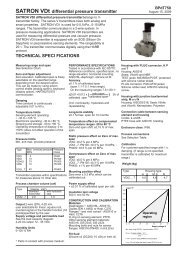
4 Electrical connections<br />
Not all components are shown<br />
U0<br />
UA<br />
I0<br />
S<br />
SMU<br />
lin<br />
C7<br />
IA<br />
D8<br />
D9<br />
SI<br />
√<br />
+ 1 2 3 4 11 13<br />
Fig. 1<br />
pin<br />
power supply<br />
pin<br />
analogue output<br />
11<br />
24/115/230 V~ 50/60 Hz<br />
1<br />
0...10 V<br />
13<br />
24/115/230 V~ 50/60 Hz<br />
2<br />
ground connection (GND)<br />
11<br />
ground connection (GND)<br />
3<br />
0...20 mA / 4...20 mA<br />
13<br />
+20,5 V...28,5 VDC<br />
4<br />
ground connection (GND)<br />
Observe rated power supply (see equipment label)<br />
Observe additional connection plan enclosed in housing lid.<br />
halstrup-walcher GmbH, 79199 Kirchzarten Operating instructions P <strong>82</strong> R Page 3 of 9
5 Analogue outputs<br />
The trans<strong>ducer</strong>'s outputs are protected against short circuit. Instruments <strong>with</strong> a direct current<br />
power supply are protected against reverse polarity of the supply voltage.<br />
The inadvertent connection of the power supply<br />
onto the output connections leads to permanent<br />
damage of the trans<strong>ducer</strong>.<br />
The flow speed or volume flow can be obtained from the so called differential pressure pro<strong>ducer</strong>.<br />
The differential pressure ∆p which occurs at the pro<strong>ducer</strong> is registered by the pressure trans<strong>ducer</strong><br />
type P <strong>82</strong> R. The following relationship is true:<br />
v ∼ q v ∼ √∆p<br />
v.....flow speed<br />
q v ...volume flow<br />
∆p...measured differential pressure<br />
The output of a P <strong>82</strong> R <strong>with</strong> a square root characteristic ("root extracted “) is directly<br />
proportional to the flow speed / volume flow. Three possible output types are available:<br />
Voltage output 0...10 V<br />
U<br />
10 V<br />
0 V<br />
U root<br />
U lin<br />
100% p<br />
U root = √ 10 V • √ U lin<br />
Current output 0...20 mA<br />
Current output 4...20 mA<br />
I<br />
I<br />
20 mA 20 mA<br />
I root<br />
I root<br />
I lin I root = √ 20 mA • √ I lin I l in I root = √ 16 mA • √ I lin - 4 mA + 4 mA<br />
4 mA<br />
0 mA<br />
100 % p 100 % P<br />
<strong>with</strong> the aid of the slide switch S (see fig. 1) it is possible to change the characteristic from "rooted"<br />
to "linear": Please note that the rooted position is indicated in German (radiziert)<br />
linear<br />
rooted √<br />
Switch S<br />
halstrup-walcher GmbH, 79199 Kirchzarten Operating instructions P <strong>82</strong> R Page 4 of 9
6 Calibration of the zero point<br />
Please note that after switching on the trans<strong>ducer</strong> requires a warm up<br />
time of approximately 30…60 minutes. During this time the output signal may<br />
be unstable.<br />
Before calibrating set the slide switch S to "Linear".<br />
The trimmer SMU (creeping suppression volume) is to be turned fully anticlockwise.<br />
After the trans<strong>ducer</strong>'s warm up time has passed the zero point can be calibrated using the trimmer<br />
U0 or trimmer I0 <strong>with</strong> current output (see fig. 1)<br />
Here it is important to ensure that no pressure is connected to the trans<strong>ducer</strong>. Likewise the pressure<br />
hoses are also to be disconnected.<br />
After calibration of the zero point the switch S must be placed back in the "rooted √" position.<br />
7 Adjustment of the creeping suppression volume<br />
U/I<br />
0...10% 100% p<br />
The creeping suppression volume provides a means of suppressing the trans<strong>ducer</strong>'s output in<br />
spite of a pressure being present, in other words the output will be held at zero. The creeping suppression<br />
volume can be set <strong>with</strong> the aid of the trimmer SMU between a value of 0…10 % of the<br />
measuring range. The use of this facility is advisable in certain applications as the repeatability<br />
of readings <strong>with</strong>in the region of very small flow speeds / volume flows is almost unachievable.<br />
Using the creeping suppression volume limits the trans<strong>ducer</strong>'s measuring<br />
range in the lower scale depending on the setting of between 0…10 %. The<br />
output will be held at "0" in spite of pressure being present.<br />
halstrup-walcher GmbH, 79199 Kirchzarten Operating instructions P <strong>82</strong> R Page 5 of 9
8 What to do in the event of a fault<br />
description of fault possible cause cure<br />
no output signal<br />
• power supply not connected<br />
• connect the correct power<br />
supply<br />
output signal remains<br />
constant in spite of<br />
changing pressure<br />
faulty output signal<br />
zero point can no longer<br />
be adjusted <strong>with</strong> U0 / I0<br />
• incorrect power supply<br />
connected<br />
• fuse blown<br />
• defective input protection diode<br />
• defective output protection diodes<br />
• pressure connections crossed<br />
over<br />
• creeping suppression volume set<br />
too high<br />
• defective output protection diode<br />
• defective pressure measurement<br />
canister<br />
• <strong>with</strong> current output load to large<br />
• <strong>with</strong> voltage output load<br />
resistance to small<br />
• defective pressure measurement<br />
canister<br />
• connect the correct power supply<br />
(see rating label)<br />
• replace fuse SI (type TR5 200 mAT<br />
from the company Wickmann)<br />
• replace diode D12( type ZPY 33)<br />
• replace D8 / D9 (type ZPY18)<br />
• connect pressure in accordance<br />
<strong>with</strong> “3. Installation“<br />
• turn the trimmer SMU anti-clock<br />
wise until the output<br />
signal ≠ 0 V / 0/4 mA<br />
• replace D8 / D9 (type ZPY18)<br />
• return instrument for repair at<br />
factory<br />
• observe maximum load of 500 Ω<br />
• minimum load resistance of 5 kΩ<br />
• return instrument for repair at<br />
factory<br />
Table 2<br />
Never perform a functional test using exhalation as this can lead to<br />
permanent damage of the pressure measuring cell.<br />
Simple functional test of the trans<strong>ducer</strong>:<br />
Connect a hose to the pressure port for positive gauge pressure + . Taking the hose<br />
between thumb and fore finger, squeeze it and then carefully move the volume of air<br />
trapped <strong>with</strong>in the hose in the direction of the trans<strong>ducer</strong>.<br />
halstrup-walcher GmbH, 79199 Kirchzarten Operating instructions P <strong>82</strong> R Page 6 of 9
9 Technical data (in accordance <strong>with</strong> DIN16086)<br />
Manufacturer:<br />
<strong>Type</strong>:<br />
Calibrated pressure<br />
forms:<br />
Measuring principle:<br />
halstrup-walcher GmbH<br />
P <strong>82</strong> R<br />
positive gauge pressure of non-aggressive gases<br />
Deflection of a copper-beryllium diaphragm is registered<br />
via an inductive pick-up<br />
Input magnitudes:<br />
Measuring ranges:<br />
Excess pressure:<br />
Maximum system<br />
pressure:<br />
0…100 Pa to 0…20 kPa (others upon request)<br />
5 times the end of scale value<br />
100 kPa<br />
Dead volume:<br />
approx. 2000 mm 3 (measuring range ≥ 250 Pa)<br />
approx. 9000 mm 3 (measuring range < 250 Pa)<br />
Control volume:<br />
200 mm 3 maximum<br />
Materials in contact <strong>with</strong> measured medium see annex A<br />
<strong>Output</strong> characteristics of the pressure sensor:<br />
Temperature coefficient<br />
of the zero signal:<br />
0,4 % / 10 K (<strong>with</strong>in the range + 10 °C to + 50 °C)<br />
Temperature coefficient<br />
of the output span: 0,4 % / 10 K (<strong>with</strong>in the range + 10 °C to + 50 °C)<br />
Deviation of the output 1 % of the output span, rooted characteristic curve<br />
characteristic curve: (best straight line)<br />
Hysteresis:<br />
Warm up time:<br />
Response time:<br />
Load resistance R L :<br />
Load R B :<br />
Power supply<br />
Supply voltage:<br />
< 0,1 % of the output span<br />
approx. 30 min.<br />
20 ms, 1s, 2s or 5s optional<br />
R L ≥ 5 kΩ (voltage output)<br />
R B < 500 Ω (current output)<br />
Power consumption:<br />
Environmental conditions<br />
Nominal temperature range: + 10 °C…+ 50 °C<br />
Operating temperature<br />
range: 0 °C…+ 60 °C<br />
Storage temperature range: - 10 °C…+ 70 °C<br />
24 V = + 20 % / - 15 % filtered permitted ripple 1000 mV<br />
24 V / 115 V / 230 V ~ + 6 % / - 15 % 50 / 60 Hz<br />
0,9 W<br />
halstrup-walcher GmbH, 79199 Kirchzarten Operating instructions P <strong>82</strong> R Page 7 of 9
EMC (electro-magnetic<br />
compatibility): corresponds to EN 50 081 part 1 and EN 50 0<strong>82</strong><br />
part 1<br />
Mechanical data<br />
Pressure connections: ∅ 6,5 mm for hose <strong>with</strong> a nominal width of 5 mm<br />
Electrical connection: screwed clamps for cable up to ∅ 2,5 mm<br />
Orientation of installation: vertical (for horizontal installation please mention on<br />
ordering, otherwise zero point to be calibrated by user)<br />
Housing dimensions: (B x L x H): 120 x 122 x 75 mm<br />
Weight:<br />
0,8 kg<br />
Enclosure protection: IP 54<br />
Annex A: Materials in contact <strong>with</strong> measured medium<br />
- Beryllium bronze CuBe2 - Araldite CY236 / HY988<br />
- Mu-metal (nickel compound) - Loctite 242e<br />
- Brass CUZn39Pb3 - Carbonised iron<br />
- Aluminium AlCuMgPb / AlMg3 - KEL (FKM: Fe[Co]5<br />
- Silicon (tubing) - Wepuran Wu 4457/51<br />
- (PTBP) - UHU-plus endfest ® 300<br />
Options<br />
• 3½ digit LCD-display<br />
• 4½ digit LCD-display<br />
• certificate of calibration (issued by the German<br />
Calibration Service {DKD})<br />
• locally issued certificate of linearity • wetted components silicone free<br />
• damping of the output signal up to 5 s<br />
halstrup-walcher GmbH, 79199 Kirchzarten Operating instructions P <strong>82</strong> R Page 8 of 9
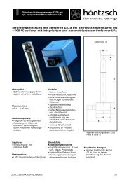
10 Dimensional drawing (not to scale)<br />
Fig. 2<br />
- subject to technical alterations -<br />
7100.001874 REV C P<strong>82</strong>R_E.DOC Su/km 26 October 2001<br />
halstrup-walcher GmbH, 79199 Kirchzarten Operating instructions P <strong>82</strong> R Page 9 of 9