3 Installation - QDIS
3 Installation - QDIS
3 Installation - QDIS

You also want an ePaper? Increase the reach of your titles
YUMPU automatically turns print PDFs into web optimized ePapers that Google loves.
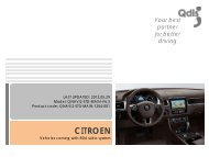
Release date : 2012.01.17<br />
Model : QVI-BM12-Main-V1.0 IF / Product code : QVI-BM12-1112-002<br />
BM12 V1.0<br />
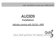
<strong>Installation</strong><br />
Your best partner for better driving
Contents<br />
1 <strong>Installation</strong> diagram<br />
2 Cautions on installation<br />
3 <strong>Installation</strong><br />
3<br />
4<br />
5<br />
www.qdis.co.kr 2
1 <strong>Installation</strong> diagram<br />
Original LCD cable<br />
Original<br />
Monitor<br />
Control box<br />
Offered 2P Power Cable<br />
Offered LCD cable<br />
Original CAN<br />
Control box<br />
CAN<br />
Green<br />
Green<br />
Green+Brown<br />
※ Connect CAN-high<br />
(Green+Brown) of the<br />
interface to Yellow+Red<br />
cable of the car.<br />
※ Connect CAN-low(Green)<br />
of the interface to<br />
Yellow+Brown cable of the<br />
car.<br />
REAR-C<br />
SAFE<br />
F-CAM-DET<br />
CAN-L<br />
CAN-H<br />
GND<br />
ACC (12V ~24V)<br />
B DATA (blue)<br />
G DATA (green)<br />
R DATA (red)<br />
DVD<br />
GND (black)<br />
SYNC (white)<br />
NAVI<br />
GND<br />
REAR (12V OUT)<br />
AV3<br />
AV2<br />
AV1<br />
REAR C<br />
Audio R<br />
Audio L<br />
AV/OUT Video<br />
www.qdis.co.kr 3
2 Cautions on installation<br />
• Ignition key should be taken off before starting installation, interface power connection must be<br />
the last step in installation.<br />
• Power cable should be separated when connecting interface.<br />
• Should be no any electronic devices or magnetic pole around installation place.<br />
• All steps of installation should be done by well-trained specialist.<br />
• Dismantling without manufacturer’s permission can not be guaranteed, (No permission to break<br />
attached label on the board.)<br />
• Kindly check all parts are in the box, when receiving the product, if anything missing, inform to the<br />
supplier or manufacturer.<br />
• According to our sales policy, any problems caused by user’s mistake, careless can not be<br />
guaranteed.<br />
www.qdis.co.kr 4
3 <strong>Installation</strong><br />
3.1 Connecting the monitor with the interface<br />
1 Connect LCD cable enclosed in our package to the spot that the<br />
original one is connected after disconnecting the original LCD cable from<br />
the monitor as shown left.<br />
※ Warning : As shown below, face of yellow is placed in the upper<br />
direction. (Red wire’s position is right)<br />
2 Connect the original LCD cable to “LCD-IN” connector of the interface.<br />
※ Warning : Power cable of interface has to be connected with Back of command or cigar jack.<br />
(Do not connect with accessory Power)<br />
www.qdis.co.kr 5
3 <strong>Installation</strong><br />
3.2 Connecting CAN cable respectively<br />
Original CAN-Low<br />
Original CAN-High<br />
Offered CAN-High<br />
Control box<br />
Offered CAN-Low<br />
POWER CABLE<br />
Connect CAN-H wire (Green+Brown) enclosed in our package with the original CAN-H wire (Yellow+Red).<br />
And connect CAN-L wire (Green) enclosed in our package with the original CAN-L wire (Yellow+Brown).<br />
www.qdis.co.kr 6