AUDI09 - qdis
AUDI09 - qdis
AUDI09 - qdis

Create successful ePaper yourself
Turn your PDF publications into a flip-book with our unique Google optimized e-Paper software.
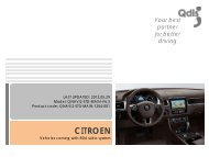
elease date : 2011.07.19<br />
model : QVI-AUD09-V6 / product code : AUD09-1107-001<br />
<strong>AUDI09</strong><br />
Installation<br />
Vehicles coming with 3G/3G+ MMI<br />
Your best partner for better driving
Contents<br />
1 Installation diagram<br />
2 Cautions on installation<br />
3 Installation<br />
4 Using original navigation button<br />
5 Connecting CAN cable<br />
3<br />
4<br />
5<br />
7<br />
8<br />
www.<strong>qdis</strong>.co.kr 2
1 Installation diagram<br />
navigation<br />
Touch cable<br />
X+<br />
Y+<br />
X-<br />
Y-<br />
Control Box<br />
Original LCD cable<br />
Monitor<br />
Touch screen<br />
DIP S/W<br />
TOUCH OUT<br />
TO NAVI<br />
LVDS<br />
OUT<br />
Offered LCD cable<br />
TO SYS<br />
TO<br />
MONITOR<br />
VIDEO INTERFACE<br />
SUB BOARD<br />
LED<br />
POWER/CAN/RGB R-CAM A/V(IN/OUT)<br />
LVDS cable<br />
TO I/F<br />
TO<br />
TOUCH<br />
Offered Touch In cable<br />
AUX-ON (N.C)<br />
REAR<br />
OPT2 (N.C)<br />
RGB<br />
CAN-L<br />
CAN-H<br />
IR-AV3 (DTV)<br />
IR-AV2 (DVD)<br />
IR-AV1 (NAVI)<br />
PARKING (SAFE)<br />
MODE : Toggle S/W<br />
IR<br />
PB12 (N.C)<br />
GPIO-ZO : MMI<br />
GND<br />
ACC<br />
GND<br />
REAR (12V OUT)<br />
AV3<br />
AV2<br />
AV1<br />
REAR C<br />
www.<strong>qdis</strong>.co.kr 3<br />
AV/OUT Video<br />
Audio R<br />
Audio L
2 Cautions on installation<br />
• Ignition key should be taken off before starting installation, interface power connection must be the last step in<br />
installation.<br />
• Power cable should be separated when connecting interface.<br />
• Should be no any electronic devices or magnetic pole around installation place.<br />
• All steps of installation should be done by well-trained specialist.<br />
• Dismantling without manufacturer’s permission can not be guaranteed, (No permission to break attached label on the<br />
board.)<br />
• Kindly check all parts are in the box, when receiving the product, if anything missing, inform to the supplier or<br />
manufacturer.<br />
• According to our sales policy, any problems caused by user’s mistake, careless can not be guaranteed.<br />
www.<strong>qdis</strong>.co.kr 4
3 Installation<br />
3.1 Separating monitor, connecting LVDS-IN cable and LCD cable<br />
Rear view of monitor<br />
Rear view of command<br />
1 Here are pictures of the rear view of the<br />
disassembled monitor and command.<br />
2 Connect the original LCD cable to “TO MONITOR” of the subboard<br />
after disconnecting it from the command.<br />
You can see that original LCD cable of<br />
monitor is connected to the command<br />
in the picture above.<br />
And connect the LCD cable enclosed in our package to “TO<br />
SYS” of the sub-board. Then connect the opposite end of the<br />
cable to the spot that the original LCD cable is connected of<br />
command<br />
www.<strong>qdis</strong>.co.kr 5
3 Installation<br />
3.2 Connecting touch screen cable and navigation touch cable<br />
Plug & Play type for<br />
TOUCH OUT cable<br />
navigation<br />
2 Connect the TOUCH OUT cable<br />
enclosed in our package to<br />
“TOUCH OUT TO NAVI” of the<br />
interface. Then connect the<br />
opposite end of it to the touch<br />
cable of navigation system.<br />
1 Connect the TOUCH IN cable enclosed<br />
in our package to the connector of<br />
touch screen. And connect the<br />
opposite end of it to “TO TOUCH” of<br />
the sub-board.<br />
www.<strong>qdis</strong>.co.kr 6
4 Using original navigation button<br />
When you use the mode change function via original navigation button, you have to connect 16pin as shown<br />
below.<br />
- Case of A8 -<br />
Find a bunch of cables connecting DVD box from the passenger seat. And connect the white one<br />
among the cables with MMI cable of POWER cable enclosed in our package.<br />
** If you handle A8 vehicle, connect the white/blue cable to the orange cable in our power cable as<br />
shown top right.<br />
www.<strong>qdis</strong>.co.kr 7
5 Connecting CAN cable<br />
If you connect the CAN cable in models including ”MODE” handle button, you can change modes via “MODE”<br />
button.<br />
Find the red connector from the passenger seat. After disassembling it, connect the CAN(H), CAN(L)<br />
enclosed in our package to the original CAN cable respectively.<br />
PIN No.15 : CAN High<br />
PIN No. 5: CAN Low<br />
www.<strong>qdis</strong>.co.kr 8