Optical DVI Daisy-chain Extender User's Manual for the M5-2000 ...
Optical DVI Daisy-chain Extender User's Manual for the M5-2000 ...
Optical DVI Daisy-chain Extender User's Manual for the M5-2000 ...

You also want an ePaper? Increase the reach of your titles
YUMPU automatically turns print PDFs into web optimized ePapers that Google loves.
<strong>Manual</strong> Contents<br />
__________________________________________<br />
<strong>Manual</strong> Contents 1-0<br />
Welcome!, Product Description 1-1<br />
System Requirements <strong>for</strong> Setup 1-2<br />
Installation 1-3<br />
Troubleshooting, Maintenance, Technical Support 1-5<br />
Product Specifications 1-6<br />
Warranty In<strong>for</strong>mation 1-7<br />
Regulatory Statements 1-8<br />
Pictorials<br />
<strong>Optical</strong> <strong>DVI</strong><br />
<strong>Daisy</strong>-<strong>chain</strong> <strong>Extender</strong><br />
Figure 1 – Overall <strong>Optical</strong> <strong>DVI</strong> daisy <strong>chain</strong> system 1-1<br />
Figure 2 – Connection of <strong>DVI</strong> cable and power adaptor<br />
in <strong>M5</strong>-<strong>2000</strong> 1-3<br />
Figure 3 – Connection of <strong>DVI</strong> cables to displays<br />
and power adaptor in <strong>M5</strong>-2001 1-3<br />
Figure 4 – Connection of duplex LC fiber cables 1-4<br />
Figure 5 – Fiber Connection between two (2) <strong>M5</strong>-2001s 1-4<br />
User’s <strong>Manual</strong><br />
<strong>for</strong> <strong>the</strong> <strong>M5</strong>-<strong>2000</strong> & 2001<br />
1- 0 <strong>Manual</strong> Contents
Welcome!<br />
Congratulations on your purchase of <strong>the</strong> optical <strong>DVI</strong> daisy <strong>chain</strong> extender,<br />
consisting of a <strong>M5</strong>-<strong>2000</strong>, <strong>Optical</strong> <strong>DVI</strong> converter and multiple <strong>M5</strong>-2001, <strong>Optical</strong><br />
<strong>DVI</strong> repeaters. This manual contains in<strong>for</strong>mation that will assist you in installing<br />
and operating <strong>the</strong> product.<br />
Product Description<br />
The <strong>M5</strong>-<strong>2000</strong> module converts <strong>DVI</strong> input into two-channel optical signals and<br />
transmits over multimode glass of fiber cables with duplex LC plugs to <strong>the</strong> <strong>M5</strong>-<br />
2001 module. Also, <strong>the</strong> <strong>M5</strong>-2001 module repeats to <strong>the</strong> next <strong>M5</strong>-2001 module<br />
and at <strong>the</strong> same time distributes into two <strong>DVI</strong> outputs. The combination of one<br />
(1) <strong>M5</strong>-<strong>2000</strong> and multiple <strong>M5</strong>-2001 makes <strong>DVI</strong> daisy <strong>chain</strong> connection<br />
remotely placed at 500m (1,670ft) in maximum between modules. For <strong>the</strong> sake<br />
of right display on connected monitors, <strong>the</strong> factory offers programming EDID of<br />
a user’s monitor to <strong>the</strong> EEPROM in <strong>the</strong> <strong>M5</strong>-<strong>2000</strong>.<br />
Shipping Group of<br />
<strong>M5</strong>-<strong>2000</strong> <strong>Optical</strong> <strong>DVI</strong> converter<br />
<br />
<br />
<br />
The converter box: One (1) Converter Box.<br />
AC/DC power adapter: One (1) +12V/3A units (including AC cord).<br />
User’s <strong>Manual</strong><br />
<strong>M5</strong>-2001 <strong>Optical</strong> <strong>DVI</strong> repeater<br />
<br />
<br />
<br />
The repeater box: One (1) Repeater Box.<br />
AC/DC power adapter: One (1) +12V/3A units (including AC cord).<br />
User’s <strong>Manual</strong><br />
System Requirements <strong>for</strong> Setup<br />
<br />
<br />
<br />
Hardware requirements<br />
• You have a graphic controller card with a <strong>DVI</strong> port in your<br />
Windows/Mac (Mac is option), or SUN system. It should support<br />
<strong>the</strong> maximum graphic resolution feature of <strong>the</strong> display to be<br />
connected.<br />
• In case of using a computer, no special memory size, CPU<br />
speed and chipsets are required.<br />
• Step-by-step connection of multiple <strong>M5</strong>-2001s is strongly<br />
recommended prior to install all <strong>M5</strong>-2001 boxes in a time.<br />
Software requirements<br />
• No special needs, if <strong>the</strong> <strong>DVI</strong> graphic controller and display<br />
peripheral are operational with <strong>the</strong> plat<strong>for</strong>m’s OS and<br />
application.<br />
AC/DC Power Adapter Technical Advisory<br />
The power of <strong>M5</strong>-<strong>2000</strong> and 2001 is designed to supply to each<br />
module of <strong>the</strong>m by plugging to each of <strong>the</strong> power plugs.<br />
Figure 1 – Overall <strong>Optical</strong> <strong>DVI</strong> daisy-<strong>chain</strong> system<br />
1-1 Welcome, Product Description<br />
1-2 System Requirements <strong>for</strong> Setup
Installation<br />
Important: Please use <strong>the</strong> installation procedure below. Improper, or no<br />
operation may result if <strong>the</strong> start-up sequence is not correctly followed.<br />
Step 1<br />
Carefully unpack <strong>the</strong> contents of <strong>the</strong> shipping group. Be<strong>for</strong>e next step, ensure<br />
that your graphic card is set at no higher than SXGA (1,280x1,024) 60Hz in<br />
direct connection of copper <strong>DVI</strong> cables.<br />
Step 2<br />
With system power turned off, connect <strong>the</strong> <strong>M5</strong>-<strong>2000</strong> converter box to <strong>the</strong> <strong>DVI</strong><br />
receptacle of a computer or a video controller by a <strong>DVI</strong> copper cable. Plug <strong>the</strong><br />
power adaptor in <strong>the</strong> shipping group and ensure its Power indicator lights on.<br />
The Link indicator will light on after <strong>the</strong> graphic cards power on. Recommend<br />
to power it after all connections are ready.<br />
Notice: Longer cables over 2m could deteriorate <strong>the</strong> overall graphic quality.<br />
Step 4<br />
Remove <strong>the</strong> module dust covers and connect a duplex LC fiber cable to LC<br />
receptacles of <strong>the</strong> <strong>M5</strong>-<strong>2000</strong> converter and <strong>M5</strong>-2001 repeater, as shown in Fig.<br />
4. Ensure plugging to <strong>the</strong> IN of two (2) duplex connectors in <strong>M5</strong>-2001. The<br />
OUT will be connected to <strong>the</strong> IN of <strong>the</strong> next <strong>M5</strong>-2001.<br />
Notice: Please make sure that you should use multimode glass of fiber.<br />
.<br />
Figure 4 – Connection of duplex LC fiber cables<br />
Notice: Please DO NOT look directly into <strong>the</strong> LC receptacles of <strong>M5</strong>-<strong>2000</strong> and<br />
<strong>the</strong> OUT of <strong>M5</strong>-2001 boxes, while <strong>the</strong>y are powered on, although <strong>the</strong>y are<br />
regulated strictly enough to operate under <strong>the</strong> Laser Class I, classified by<br />
CDRH/FDA <strong>for</strong> eye safety.<br />
Step 5<br />
If you have ano<strong>the</strong>r <strong>M5</strong>-2001, follow as Step 3 and connect <strong>the</strong> duplex LC<br />
multimode fiber cables to <strong>the</strong> next <strong>M5</strong>-2001 as Step 4. The fiber connection is<br />
accomplished between <strong>the</strong> OUT of <strong>the</strong> prior <strong>M5</strong>-2001 and <strong>the</strong> IN of <strong>the</strong> next<br />
one. You have to repeat Step 5 as many as you have.<br />
Figure 2 – Connection of <strong>DVI</strong> cable and power adaptor in <strong>M5</strong>-<strong>2000</strong><br />
Step 3<br />
In <strong>the</strong> same way as above, connect <strong>the</strong> repeater box, <strong>M5</strong>-2001 with two (2)<br />
<strong>DVI</strong> copper cables into each of displays. Plug <strong>the</strong> power adaptor to <strong>the</strong> <strong>M5</strong>-<br />
2001 and ensure its Power indicator lights on.<br />
Figure 3 – Connection of <strong>DVI</strong> cables to displays and power adaptor in <strong>M5</strong>-2001<br />
1-3 Installation<br />
Figure 5 – Fiber Connection between two <strong>M5</strong>-2001s<br />
Step 6<br />
Power on <strong>the</strong> computer and displays or connected devices, if not ON. Ensure<br />
<strong>the</strong> Link indicators light on, presenting detecting signals and secure<br />
connection of LC duplex fiber cables and of <strong>the</strong> <strong>DVI</strong> cable in <strong>the</strong> <strong>M5</strong>-<strong>2000</strong><br />
box.<br />
Tip 1: After initial installation as guided in <strong>the</strong> above, we recommend you to<br />
power On and Off while all connections are set and <strong>the</strong> converter and<br />
repeaters are powered On.<br />
Tip 2: Avoid “hot plugging” <strong>the</strong> converter or repeater boxes as this is not<br />
recommended practice with live digital voltages.<br />
1-4 Installation (continued)
Troubleshooting<br />
The display displays only black screen.<br />
• Check that all AC and DC plugs and jacks used by external power<br />
supplies (both Opticis and o<strong>the</strong>rs) are firmly connected.<br />
• Ensure that power bars are live.<br />
• Ensure that <strong>the</strong> converter and repeater boxes plug correctly to <strong>the</strong><br />
computer and display, respectively.<br />
• Check if <strong>the</strong> computer and display are powered on and properly<br />
booted.<br />
• Ensure your graphic card is set at not higher than SXGA<br />
(1,248x1,024) at 60Hz refresh ratio.<br />
• Ensure <strong>the</strong> programmed EDID be compatible with that of <strong>the</strong><br />
connected monitors.<br />
• Reset <strong>the</strong> converter and each of repeaters by de-plugging and replugging<br />
<strong>the</strong> power adaptors.<br />
• Re-boot up <strong>the</strong> system after reconnecting <strong>the</strong> optical system cable.<br />
Screen is distorted or displays noises.<br />
• Check if <strong>the</strong> graphic resolution is properly set. Go to <strong>the</strong> display<br />
properties and tap <strong>the</strong> settings. Ensure that <strong>the</strong> resolution sets less<br />
than SXGA (1,248x1,024) at 60Hz refresh ratio.<br />
• Reset <strong>the</strong> converter and each of repeaters or <strong>the</strong> system.<br />
• Power down, disconnect and reconnect <strong>the</strong> optical system cable or<br />
DC power adaptors, and power up.<br />
Maintenance<br />
No special maintenance is required <strong>for</strong> <strong>the</strong> optical system cables and power<br />
supplies. Ensure that <strong>the</strong> cables and power modules are stored or used in a<br />
benign environment free from liquid or dirt contamination.<br />
There are no user serviceable parts. Refer all service and repair issues to<br />
Opticis or its authorized distributor.<br />
Technical Support and Service<br />
For commercial or general product support, contact your reseller. For<br />
technical service, contact Opticis by email techsupp@opticis.com or visit its<br />
website at www.opticis.com.<br />
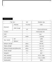
Product Specifications<br />
<strong>M5</strong>-<strong>2000</strong> and 2001 <strong>Optical</strong> <strong>DVI</strong> daisy <strong>chain</strong> <strong>Extender</strong><br />
<br />
<br />
<br />
<br />
<br />
<br />
Compliance with <strong>DVI</strong> standard: supports <strong>DVI</strong> 1.0 of DDWG, using<br />
fiber-optic communication links.<br />
Extension limit: 500 m (1,670 feet) <strong>for</strong> SXGA (1,248x1,024) 24bit<br />
color at 60Hz refresh rate in ultimate operation.<br />
Fiber-optic Connection: The converter, <strong>M5</strong>-<strong>2000</strong> and repeater<br />
boxes, <strong>M5</strong>-2001 have duplex LC receptacles connected to two 50 or<br />
62.5/125µm or Multi Mode glass fibers cables.<br />
Virtual DDC: Offers <strong>the</strong> factory programming of EDID of user’s<br />
monitors, considering all monitors to be connected be compatible<br />
with <strong>the</strong> programmed data.<br />
Mechanical specifications of Uplink and Downlink boxes<br />
• Dimensions: 180mm / 125mm / 30mm (W/H/D)<br />
• Weight: 800.0 ± 3.0 gram <strong>for</strong> <strong>M5</strong>-<strong>2000</strong> and <strong>M5</strong>2001.<br />
Environmental Specifications<br />
• Operating temperature: 0°C to 50°C<br />
• Storage temperature: - 20°C to 70°C<br />
AC/DC Power Adapter<br />
<br />
<br />
Power Input: Universal AC 85-264V, 50/60Hz, AC power cord with<br />
power jack.<br />
Power Output: +12 V, 3.0 A SMPS DC-power Adapter<br />
Cord DC Jack & length: Core is 12 V and outer cylinder is GND.<br />
Length is 18.5 cm<br />
AC Cord length: 1.8m<br />
<br />
Certification: PSE, UL, cUL, FCC, CE, TUV-GS<br />
1-5 Troubleshooting, Maintenance, Technical Support<br />
1-6 Product Specifications
Warranty In<strong>for</strong>mation<br />
1 (One) Year Warranty<br />
Opticis warrants this optical <strong>DVI</strong> daisy <strong>chain</strong> <strong>Extender</strong> to be free from defects<br />
in workmanship and materials, under normal use and service, <strong>for</strong> a period of<br />
one (1) year from <strong>the</strong> date of purchase from Opticis or its authorized resellers.<br />
If a product does not work as warranted during <strong>the</strong> applicable warranty period,<br />
Opticis shall, at its option and expense, repair <strong>the</strong> defective product or part,<br />
deliver to customer an equivalent product or part to replace <strong>the</strong> defective item,<br />
or refund to customer <strong>the</strong> purchase price paid <strong>for</strong> <strong>the</strong> defective product.<br />
All products that are replaced will become <strong>the</strong> property of Opticis.<br />
Replacement products may be new or reconditioned.<br />
Any replaced or repaired product or part has a ninety (90) day warranty or <strong>the</strong><br />
reminder of <strong>the</strong> initial warranty period, whichever is longer.<br />
Opticis shall not be responsible <strong>for</strong> any software, firmware, in<strong>for</strong>mation, or<br />
memory data of customer contained in, stored on, or integrated with any<br />
products returned to Opticis <strong>for</strong> repair under warranty or not.<br />
Warranty Limitation and Exclusion<br />
Opticis shall have no fur<strong>the</strong>r obligation under <strong>the</strong> <strong>for</strong>egoing limited warranty if<br />
<strong>the</strong> product has been damaged due to abuse, misuse, neglect, accident,<br />
unusual physical or electrical stress, unauthorized modifications, tampering,<br />
alterations, or service o<strong>the</strong>r than by Opticis or its authorized agents, causes<br />
o<strong>the</strong>r than from ordinary use or failure to properly use <strong>the</strong> product in <strong>the</strong><br />
application <strong>for</strong> which said product is intended.<br />
FCC/CE Statement <strong>for</strong> regulation of Electro-magnetic<br />
emission<br />
This device complies with part 15 of FCC Rules. Operation is subject to <strong>the</strong><br />
following two conditions: (1) this device may not cause harmful interference, and<br />
(2) this device must accept any interference received, including interference that<br />
may cause undesired operation. This equipment has been tested and found to<br />
comply with <strong>the</strong> limits <strong>for</strong> a Class B digital device, pursuant to part 15 and 2 of<br />
FCC Rules, EN 55022/55024/61000-3 <strong>for</strong> CE certification. These limits are<br />
designed to provide reasonable protection against harmful interference when<br />
<strong>the</strong> equipment is operated in a residential installation. This equipment<br />
generates, uses, and can radiate radio frequency energy and. if not installed<br />
and used in accordance with <strong>the</strong> instruction guide, may cause harmful<br />
interference to radio communications. However, <strong>the</strong>re is no guarantee that<br />
interference will not occur in a particular installation. If this equipment does<br />
cause harmful interference to radio or television reception, which can be<br />
determined by turning <strong>the</strong> equipment off and on, <strong>the</strong> user is encouraged to try to<br />
correct <strong>the</strong> interference by one or more of <strong>the</strong> following measures:<br />
• Re-orient or relocate <strong>the</strong> receiving antenna.<br />
• Increase <strong>the</strong> separation between <strong>the</strong> equipment and <strong>the</strong> receiver.<br />
• Connect <strong>the</strong> equipment into an outlet on a circuit different from that to which<br />
<strong>the</strong> receiver is connected.<br />
• Consult a service representative <strong>for</strong> help.<br />
Properly shielded and grounded cables and connectors must be used in order<br />
to comply with FCC/CE emission limits. Changes or modifications not expressly<br />
approved by <strong>the</strong> party responsible <strong>for</strong> compliance could void <strong>the</strong> user s authority<br />
to operate <strong>the</strong> equipment.<br />
Certification <strong>for</strong> Safety<br />
The extension system is certified pursuant to IEC60065 and its AC/DC power<br />
adapter is certified by UL1310, 1950, 60950 <strong>for</strong> North America, cUL or CSA <strong>for</strong><br />
Canada, TUV-CE & GS <strong>for</strong> EU and PSE <strong>for</strong> Japan.<br />
Certification of Eye Safety<br />
This laser product is inside implemented by using 1310nm/1550nm Bi-di<br />
Transceivers, manufactured by Opticis Co., Ltd., which are all certified by<br />
CDRH/FDA referred in Accession Number 0210774 as classified in Laser<br />
Class1.<br />
1-7 Warranty In<strong>for</strong>mation<br />
1-8 Regulatory Statements
© 2007 Opticis. All Rights Reserved<br />
Revision 1 1230