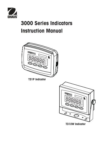
3000 Series Indicators Instruction Manual - MaRCo
3000 Series Indicators Instruction Manual - MaRCo
3000 Series Indicators Instruction Manual - MaRCo

Create successful ePaper yourself
Turn your PDF publications into a flip-book with our unique Google optimized e-Paper software.
<strong>3000</strong> <strong>Series</strong> <strong>Indicators</strong><br />
<strong>Instruction</strong> <strong>Manual</strong><br />
T31P Indicator<br />
T31XW Indicator<br />
i
Compliance to the following standards is indicated by the corresponding marking on the product.<br />
Marking<br />
Standard<br />
This product conforms to the EMC Directive 89/336/EEC, the Low Voltage Directive 73/23/EEC<br />
and the Non-automatic Weighing Instruments Directive 90/384/EEC. The complete Declaration of<br />
Conformity is available from Ohaus Corporation.<br />
AS/NZS4251.1, AS/NZS4252.1<br />
Important Notice for verified weighing instruments<br />
Weighing Instruments verified at the place of manufacture bear one of the preceding marks on the packing<br />
label and the green ‘M’ (metrology) sticker on the descriptive plate. They may be put into service<br />
immediately.<br />
Weighing Instruments to be verified in two stages have no green ‘M’ (metrology) on the descriptive plate<br />
and bear one of the preceding identification mark on the packing label. The second stage of the initial<br />
verification must be carried out by the approved service organization of the authorized representative<br />
within the EC or by the national weights & measures (W+M) authorities.<br />
The first stage of the initial verification has been carried out at the manufacturer’s work. It comprises all tests according to the<br />
adopted European standard EN 45501:1992, paragraph 8.2.2.<br />
If national regulations limit the validity period of the verification, the user of the weighing instrument must strictly observe the<br />
re-verification period and inform the respective W+M authorities.<br />
iii
Disposal<br />
In conformance with the European Directive 2002/96/EC on Waste Electrical and Electronic Equipment<br />
(WEEE) this device may not be disposed of in domestic waste. This also applies to countries outside<br />
the EU, per their specific requirements.<br />
Please dispose of this product in accordance with local regulations at the collecting point specified for<br />
electrical and electronic equipment.<br />
If you have any questions, please contact the responsible authority or the distributor from which you<br />
purchased this device.<br />
Should this device be passed on to other parties (for private or professional use), the content of this<br />
regulation must also be related.<br />
Thank you for your contribution to environmental protection.<br />
FCC Note<br />
This equipment has been tested and found to comply with the limits for a Class A digital device, pursuant to Part 15 of the FCC<br />
Rules. These limits are designed to provide reasonable protection against harmful interference when the equipment is operated<br />
in a commercial environment. This equipment generates, uses, and can radiate radio frequency energy and, if not installed<br />
and used in accordance with the instruction manual, may cause harmful interference to radio communications. Operation of<br />
this equipment in a residential area is likely to cause harmful interference in which case the user will be required to correct the<br />
interference at his own expense.<br />
Industry Canada Note<br />
This Class A digital apparatus complies with the Canadian ICES-003.<br />
Cet appareil numérique de la classe A est conforme à la Norme NMB-003 du Canada.<br />
ISO 9001 Registration<br />
In 1994, Ohaus Corporation, USA, was awarded a certificate of registration to ISO 9001 by Bureau Veritus Quality International<br />
(BVQI), confirming that the Ohaus quality management system is compliant with the ISO 9001 standard’s requirements. On May<br />
15, 2003, Ohaus Corporation, USA, was re-registered to the ISO 9001:2000 standard.<br />
iv
<strong>3000</strong> <strong>Series</strong> <strong>Indicators</strong><br />
EN-1<br />
TABLE OF CONTENTS<br />
1. INTRODUCTION ..........................................................................................................................................EN-4<br />
1.1 Safety Precautions .....................................................................................................................................EN-4<br />
1.2 Overview of Parts and Controls ...................................................................................................................EN-5<br />
1.3 Control Functions .......................................................................................................................................EN-9<br />
2. INSTALLATION .........................................................................................................................................EN-10<br />
2.1 Unpacking ..............................................................................................................................................EN-10<br />
2.2 External Connections ................................................................................................................................EN-10<br />
2.2.1 RS232 Interface Cable to T31P........................................................................................................EN-10<br />
2.2.2 AC Power to T31P ........................................................................................................................EN-10<br />
2.2.3 AC Power to T31XW .......................................................................................................................EN-10<br />
2.2.4 Battery power (T31P only) ..............................................................................................................EN-11<br />
2.2.5 Mounting Bracket to T31XW ............................................................................................................EN-11<br />
2.3 Internal Connections .................................................................................................................................EN-11<br />
2.3.1 Opening the Housing .......................................................................................................................EN-11<br />
2.3.2 Scale Base to T31P or T31XW .......................................................................................................EN-12<br />
2.3.3 RS232 Interface Cable to T31XW ......................................................................................................EN-12<br />
2.4 T31P Rear Cover Orientation .....................................................................................................................EN-13<br />
2.5 Direct Wall Mounting (T31P only) .............................................................................................................EN-13<br />
2.6 Mounting Bracket (T31XW only) ................................................................................................................EN-13<br />
3. SETTINGS ................................................................................................................................................EN-14<br />
3.1 Menu Structure ........................................................................................................................................EN-14<br />
3.2 Menu Navigation .....................................................................................................................................EN-15<br />
3.3 Calibration Menu .....................................................................................................................................EN-15<br />
3.3.1 Span Calibration ...........................................................................................................................EN-16<br />
3.3.2 Linearity Calibration ......................................................................................................................EN-16<br />
3.3.3 Geographical Adjustment Factor .....................................................................................................EN-17<br />
3.3.4 End Calibration .............................................................................................................................EN-17<br />
3.4 Setup Menu .............................................................................................................................................EN-19<br />
3.4.1 Reset ...........................................................................................................................................EN-19<br />
3.4.2 Legal for trade ..............................................................................................................................EN-19<br />
3.4.3 Calibration Unit .............................................................................................................................EN-19<br />
3.4.4 Capacity ......................................................................................................................................EN-19<br />
3.4.5 Graduation ...................................................................................................................................EN-21<br />
3.4.6 Power On Unit ..............................................................................................................................EN-21<br />
3.4.7 Zero Range ..................................................................................................................................EN-21<br />
3.4.8 End Setup ....................................................................................................................................EN-21
EN-2<br />
<strong>3000</strong> <strong>Series</strong> <strong>Indicators</strong><br />
TABLE OF CONTENTS (Cont.)<br />
3.5 Readout Menu .........................................................................................................................................EN-21<br />
3.5.1 Reset ...........................................................................................................................................EN-21<br />
3.5.2 Filter ............................................................................................................................................EN-22<br />
3.5.3 Auto-Zero Tracking ........................................................................................................................EN-22<br />
3.5.4 Backlight .....................................................................................................................................EN-22<br />
3.5.5 Auto Off Timer ..............................................................................................................................EN-22<br />
3.5.6 End Readout .................................................................................................................................EN-22<br />
3.6 Mode Menu .............................................................................................................................................EN-23<br />
3.6.1 Reset ...........................................................................................................................................EN-23<br />
3.6.2 Parts Counting Mode .....................................................................................................................EN-23<br />
3.6.3 End Mode ....................................................................................................................................EN-23<br />
3.7 Unit Menu ...............................................................................................................................................EN-24<br />
3.7.1 Reset ...........................................................................................................................................EN-24<br />
3.7.2 Kilogram Unit ...............................................................................................................................EN-24<br />
3.7.3 Pound Unit ...................................................................................................................................EN-24<br />
3.7.4 Gram Unit ....................................................................................................................................EN-24<br />
3.7.5 Ounce Unit ...................................................................................................................................EN-24<br />
3.7.6 Pound Ounce Unit .........................................................................................................................EN-24<br />
3.7.7 End Unit ......................................................................................................................................EN-24<br />
3.8 Print Menu ..........................................................................................................................................EN-25<br />
3.8.1 Reset ...........................................................................................................................................EN-25<br />
3.8.2 Baud ...........................................................................................................................................EN-25<br />
3.8.3 Parity ..........................................................................................................................................EN-25<br />
3.8.4 Stop Bit .......................................................................................................................................EN-25<br />
3.8.5 Handshake ..................................................................................................................................EN-26<br />
3.8.6 Print Stable Data Only ...................................................................................................................EN-26<br />
3.8.7 Auto Print .....................................................................................................................................EN-26<br />
3.8.8 Content ........................................................................................................................................EN-26<br />
3.8.9 End Print .....................................................................................................................................EN-26<br />
3.9 Menu Lock Menu .....................................................................................................................................EN-27<br />
3.9.1 Reset ...........................................................................................................................................EN-27<br />
3.9.2 Lock Calibration ...........................................................................................................................EN-27<br />
3.9.3 Lock Setup ...................................................................................................................................EN-27<br />
3.9.4 Lock Readout ...............................................................................................................................EN-27<br />
3.9.5 Lock Mode ...................................................................................................................................EN-27<br />
3.9.6 Lock Unit .....................................................................................................................................EN-27<br />
3.9.7 Lock Print ...................................................................................................................................EN-28<br />
3.9.8 End Lock .....................................................................................................................................EN-28
<strong>3000</strong> <strong>Series</strong> <strong>Indicators</strong><br />
EN-3<br />
TABLE OF CONTENTS (Cont.)<br />
3.10 Security Switch .......................................................................................................................................EN-28<br />
4. OPERATION .............................................................................................................................................EN-28<br />
4.1 Turning Indicator On/Off ............................................................................................................................EN-28<br />
4.2 Zero Operation .........................................................................................................................................EN-28<br />
4.3 <strong>Manual</strong> Tare ............................................................................................................................................EN-28<br />
4.4 Changing Units of Measure .......................................................................................................................EN-29<br />
4.5 Printing Data ...........................................................................................................................................EN-29<br />
4.6 Application Modes ...................................................................................................................................EN-29<br />
4.6.1 Weighing .....................................................................................................................................EN-29<br />
4.6.2 Parts Counting .............................................................................................................................EN-29<br />
5. SERIAL COMMUNICATION ..........................................................................................................................EN-31<br />
5.1 Interface Commands ................................................................................................................................EN-31<br />
5.2 Output Format .........................................................................................................................................EN-32<br />
6. LEGAL FOR TRADE ...................................................................................................................................EN-33<br />
6.1 Settings ..................................................................................................................................................EN-33<br />
6.2 Verification ..............................................................................................................................................EN-33<br />
6.3 Sealing ...................................................................................................................................................EN-33<br />
7. MAINTENANCE .........................................................................................................................................EN-34<br />
7.1 Model T31P Cleaning ...............................................................................................................................EN-34<br />
7.2 Model T31XW Cleaning ............................................................................................................................EN-34<br />
7.3 Troubleshooting .......................................................................................................................................EN-34<br />
7.4 Service Information ..................................................................................................................................EN-35<br />
8. TECHNICAL DATA .....................................................................................................................................EN-36<br />
8.1 Specifications ..........................................................................................................................................EN-36<br />
8.2 Accessories and Options ...........................................................................................................................EN-37<br />
8.3 Drawings and Dimensions ........................................................................................................................EN-38
EN-4<br />
<strong>3000</strong> <strong>Series</strong> <strong>Indicators</strong><br />
1. INTRODUCTION<br />
This manual contains installation, operation and maintenance instructions for the T31P and T31XW <strong>Indicators</strong>. Please read this<br />
manual completely before installation and operation.<br />
1.1 Safety Precautions<br />
For safe and dependable operation of this equipment, please comply with the following safety precautions:<br />
• Verify that the input voltage range printed on the data label matches the local AC power to be used.<br />
• Make sure that the power cord does not pose a potential obstacle or tripping hazard.<br />
• Use only approved accessories and peripherals.<br />
• Operate the equipment only under ambient conditions specified in these instructions.<br />
• Disconnect the equipment from the power supply before cleaning.<br />
• Do not operate the equipment in hazardous or unstable environments.<br />
• Do not immerse the equipment in water or other liquids.<br />
• Service should only be performed by authorized personnel.<br />
• The T31XW is supplied with a grounded power cable. Use only with a compatible grounded power outlet.
<strong>3000</strong> <strong>Series</strong> <strong>Indicators</strong><br />
EN-5<br />
1.2 Overview of Parts and Controls<br />
1<br />
2<br />
3<br />
4<br />
5<br />
6<br />
7<br />
TABLE 1-1. T31P PARTS.<br />
Item Description<br />
1 Data Label<br />
2 Front Housing<br />
3 Control Panel<br />
4 Security Screw<br />
5 Key Hole (4) for wall<br />
mounting<br />
6 Screw (4)<br />
7 Data Label<br />
8 Rear Housing<br />
9 Power Receptacle<br />
10 Strain Relief for Load Cell<br />
Cable<br />
11 RS232 Connector<br />
8<br />
9 10 11<br />
Figure 1-1. T31P Indicator.
EN-6<br />
<strong>3000</strong> <strong>Series</strong> <strong>Indicators</strong><br />
1.2 Overview of Parts and Controls (Cont.)<br />
1<br />
2<br />
3<br />
4<br />
5<br />
TABLE 1-2. T31XW PARTS.<br />
Item Description<br />
1 Data Label<br />
2 Front Housing<br />
3 Adjusting Knob (2)<br />
4 Control Panel<br />
5 Mounting Bracket<br />
6 Screw (4)<br />
7 Rear Housing<br />
8 Data Label<br />
9 Strain Relief for RS232<br />
10 Strain Relief for Load Cell<br />
Cable<br />
11 Power cord<br />
6<br />
7<br />
8<br />
9 10 11<br />
Figure 1-2. T31XW Indicator.
<strong>3000</strong> <strong>Series</strong> <strong>Indicators</strong><br />
EN-7<br />
1.2 Overview of Parts and Controls (Cont.)<br />
J4<br />
OFF<br />
ON<br />
9<br />
J5<br />
W1<br />
W2<br />
J7<br />
J6<br />
1 2 3 4 5 6 7 8<br />
Figure 1-3. Main PC Board.<br />
TABLE 1-3. MAIN PC BOARD.<br />
LOAD CELL WIRING<br />
+EXC +SIG -SIG -EXC<br />
+SENS GND -SENS<br />
Item Description<br />
1 Keypad Connector J4 T31XW Model only<br />
2 Battery Connector (T31P only)<br />
3 Line Power Input<br />
4 Sense Jumper W1<br />
5 Load Cell Terminal Block J5<br />
6 Sense Jumper W2<br />
7 RS232 Terminal Block J7 T31XW Model only<br />
8 RS232 Connector J6 T31P Model only<br />
9 LFT On / Off Switch<br />
RS232 WIRING<br />
TXD<br />
GND<br />
RXD
EN-8<br />
<strong>3000</strong> <strong>Series</strong> <strong>Indicators</strong><br />
1.2 Overview of Parts and Controls (Cont.)<br />
1<br />
14<br />
2<br />
3<br />
4<br />
13<br />
12<br />
11<br />
10 9 8 7<br />
6<br />
5<br />
Figure 1-4. Controls and <strong>Indicators</strong>.<br />
TABLE 1-4. CONTROL PANEL.<br />
No. Designation<br />
1 Capacity Label Window<br />
2 Pound symbol<br />
3 Ounce symbol<br />
4 Kilogram, gram symbols<br />
5 TARE Menu button<br />
6 TARE function symbol<br />
7 FUNCTION Mode button<br />
8 NET function symbol<br />
9 PCS function symbol<br />
10 PRINT Units button<br />
11 Battery function symbol<br />
(T31P only)<br />
12 ON/ZERO Off button<br />
13 Center of Zero Indicator
<strong>3000</strong> <strong>Series</strong> <strong>Indicators</strong><br />
EN-9<br />
1.3 Control Functions<br />
TABLE 1-5. CONTROL FUNCTIONS.<br />
Button<br />
Primary Function<br />
ON/ZERO<br />
PRINT<br />
FUNCTION<br />
TARE<br />
(Short Press)<br />
If Indicator is On, sets<br />
Sends the current value<br />
Initiates an application<br />
Performs a tare<br />
zero.<br />
to the COM port if<br />
mode.<br />
operation.<br />
AUTOPRINT is set to Off.<br />
Secondary Function<br />
Off<br />
Units<br />
Mode<br />
Menu<br />
(Long Press)<br />
Turns the Indicator on<br />
Changes the weighing<br />
Allows changing the<br />
Enter the User menu.<br />
or off.<br />
Unit.<br />
application mode.<br />
Press and hold allows<br />
scrolling through modes.<br />
Menu Function<br />
Yes<br />
No<br />
Back<br />
Exit<br />
(Short Press)<br />
Accepts the current<br />
Advances to the next<br />
Moves Back to previous<br />
Exits the User menu.<br />
setting on the display.<br />
menu or menu item.<br />
menu item.<br />
Aborts the calibration in<br />
Rejects the current<br />
Decrements the value.<br />
progress.<br />
setting on the display<br />
and advances to the<br />
next available setting.<br />
Increments the value.
EN-10<br />
<strong>3000</strong> <strong>Series</strong> <strong>Indicators</strong><br />
2. INSTALLATION<br />
2.1 Unpacking<br />
Unpack the following items:<br />
• T31P or T31XW Indicator<br />
• AC Adapter (T31P only)<br />
• Mounting Bracket (supplied with T31XW only)<br />
• Knobs (2) (supplied with T31XW only)<br />
• Capacity Label Sheet<br />
• <strong>Instruction</strong> <strong>Manual</strong> CD<br />
• Warranty Card<br />
• LFT sealing Kit<br />
2.2 External Connections<br />
2.2.1 RS232 interface Cable to T31P<br />
Connect the optional RS232 cable to the RS232 connector Figure 1-1, item 13).<br />
Pin<br />
Connection<br />
1 N/C<br />
2 TXD<br />
3 RXD<br />
4 N/C<br />
5 GND<br />
5 4<br />
9<br />
8<br />
3<br />
7<br />
2<br />
6<br />
1<br />
6 N/C<br />
7 N/C<br />
8 N/C<br />
Figure 2-1. RS232 Pins.<br />
9 N/C<br />
2.2.2 AC Power to T31P<br />
Connect the AC Adapter to the power receptacle (Figure 1-1, item 8), then plug the AC Adapter into an electrical outlet.<br />
2.2.3 AC Power to T31XW<br />
Connect the AC plug to a properly grounded electrical outlet.
<strong>3000</strong> <strong>Series</strong> <strong>Indicators</strong><br />
EN-11<br />
2.2.4 Battery Power (T31P Only)<br />
The indicator can be operated on the internal rechargeable battery when AC power is not available. The indicator will<br />
automatically switch to battery operation if there is a power failure or the power cord is removed.<br />
Note:<br />
Before using the indicator for the first time, the internal rechargeable battery should be fully charged for up to<br />
12 hours. The indicator can be operated during the charging process. The battery is protected against over<br />
charging and the indicator can remain connected to the AC power line.<br />
Connect AC power to the indicator and allow it to charge. While the battery is charging, the triangle above the battery function<br />
symbol will light. When the battery is fully charged, this triangle will disappear.<br />
The indicator can operate for up to 100 hours on a fully charged battery.<br />
During battery operation, a flashing triangle above the battery function symbol indicates the battery is low and requires<br />
recharging. Approximately 60 minutes of operation will remain when the battery symbol starts to blink. The indicator will<br />
display Lo.BAT and automatically turn off when the battery is fully discharged.<br />
CAUTION<br />
BATTERY IS TO BE REPLACED ONLY BY AN AUTHORIZED OHAUS<br />
SERVICE DEALER.<br />
RISK OF EXPLOSION CAN OCCUR IF REPLACED WITH THE<br />
WRONG TYPE OR CONNECTED IMPROPERLY.<br />
Dispose of the lead acid battery according to local laws and regulations.<br />
2.2.5 Mounting Bracket to T31XW<br />
Align the mounting bracket over the threaded holes in the side of the indicator and install the knobs. Adjust the indicator to the<br />
desired angle and tighten the knobs.<br />
2.3 Internal Connections<br />
Some connections require the housing to be opened.<br />
2.3.1 Opening the Housing<br />
CAUTION: ELECTRICAL SHOCK HAZARD. REMOVE ALL POWER CONNECTIONS TO THE INDICATOR<br />
BEFORE SERVICING OR MAKING INTERNAL CONNECTIONS. THE HOUSING SHOULD ONLY BE OPENED<br />
BY AUTHORIZED AND QUALIFIED PERSONNEL, SUCH AS AN ELECTRICAL TECHNICIAN.
EN-12<br />
<strong>3000</strong> <strong>Series</strong> <strong>Indicators</strong><br />
T31P<br />
Remove the four Phillips head screws from the rear housing.<br />
Open the housing being careful not to disturb the internal connections.<br />
Once all connections are made, reattach the front housing.<br />
T31XW<br />
Remove the four hex head screws from the rear housing.<br />
Open the housing by carefully pulling the top of the front housing forward.<br />
Once all connections are made, reattach the front housing.<br />
The screws should be tightened fully to maintain a watertight seal.<br />
2.3.2 Scale Base to T31P or T31XW<br />
Pass the load cell cable through the strain relief (Figure 1-1, item 9 or Figure 1-2,<br />
item 10) and attach it to terminal block J5 (Figure 1-3, item 5).<br />
Re-tighten the strain relief to ensure a watertight seal.<br />
Jumper Connections<br />
For a 4-wire load cell with no sense wires: Jumpers W2 and W3 must be shorted.<br />
For a 6-wire load cell that includes sense wires, see Figure 2-2. Jumpers W2 and W3 must<br />
be opened.<br />
For load cells with an extra ground shield wire: Connect the shield to the center position (GND)<br />
of J5.<br />
Pin Connection<br />
J5-1 +EXCITATION<br />
J5-2 +SENSE<br />
J5-3 +SIGNAL<br />
J5-4 GND<br />
J5-5 -SIGNAL<br />
J5-6 -SENSE<br />
J5-7 -EXCITATION<br />
Figure 2-2. Jumper Connections.<br />
After wiring is completed and jumpers are in place, replace the indicator housing screws. Make sure the strain relief is properly<br />
tightened.<br />
2.3.3 RS232 Interface Cable to T31XW<br />
Pass the optional RS232 cable through the strain relief (Figure 1-2, item 9) and attach it to<br />
terminal block J7 (Figure 1-3, item 7). Re-tighten the strain relief to ensure a water tight seal.<br />
Pin Connection<br />
J7-1 TXD<br />
J7-2 RXD<br />
J7-3 GND
<strong>3000</strong> <strong>Series</strong> <strong>Indicators</strong><br />
EN-13<br />
2.4 T31P Rear Cover Orientation<br />
The T31P is delivered in the wall mount orientation<br />
with the connections exiting below the display. The<br />
rear housing may be reversed so the connections<br />
exit above the display when the T31P is placed<br />
horizontally on a bench. See Figure 2-4. To reverse<br />
the rear housing, remove the four Phillips head<br />
screws, carefully rotate the housing 180°, and<br />
reinstall the screws.<br />
CAUTION: Take care not to pinch any internal<br />
cables attached inside.<br />
Figure 2-3. Wall Mount Configuration.<br />
Figure 2-4. Bench Top Configuration.<br />
2.5 Direct Wall Mounting (T31P only)<br />
The T31P indicator may be mounted directly to a wall using two screws (not included). Select appropriate size screws that fit<br />
into the holes at the bottom of the indicator housing. See Figure 2-5. When mounting to a wall without a solid backing, use<br />
appropriate anchoring hardware.<br />
Wall Mounting Holes<br />
Figure 2-5. T31P Direct Wall Mounting.<br />
2.6 Mounting Bracket (T31XW only)<br />
Attach the bracket to a wall or table using fasteners (not supplied) that are appropriate for the type of mounting surface. The<br />
bracket will accommodate up to 6 mm (1/4”) diameter screws. Locate the mounting holes as shown in Figure 2-6.<br />
Figure 2-6. Mounting Bracket Dimensions.
EN-14<br />
<strong>3000</strong> <strong>Series</strong> <strong>Indicators</strong><br />
3 SETTINGS<br />
3.1 Menu Structure<br />
TABLE 3-1. MENU STRUCTURE.
<strong>3000</strong> <strong>Series</strong> <strong>Indicators</strong><br />
EN-15<br />
3.2 Menu Navigation<br />
TO ENTER THE MENU MODE<br />
Press and hold the Menu button until MENU appears on the display. The first upper level menu appears on the display.<br />
Summary of button navigation functions in menu mode:<br />
--Yes Allows entry into the displayed menu.<br />
- Accepts the displayed setting and advances to the next menu item.<br />
--No Skips by the displayed menu.<br />
- Rejects the displayed setting or menu item and advances to the next available item.<br />
--Back Moves backwards through the upper and middle level menus.<br />
- Backs out of a list of selectable items to the previous middle level menu.<br />
--Exit Exits from menu directly to the active weighing mode.<br />
3.3 Calibration Menu<br />
Two calibration processes are available: Span Calibration and Linearity<br />
Calibration.<br />
NOTES:<br />
1. Make sure that appropriate calibration masses are available before<br />
beginning calibration.<br />
2. Make sure that the scale base is level and stable during the entire<br />
calibration process.<br />
3. Calibration is unavailable with LFT set to On.<br />
4. Allow the Indicator to warm up for approximately 5 minutes after<br />
stabilizing to room temperature.<br />
5. To abort calibration, press the Exit button anytime during the calibration<br />
process.<br />
Span Perform<br />
Linearity Perform<br />
Geographic<br />
Adjustment Set 00…Set 19… Set 31<br />
End Calibration Exit CALIBRATE menu
EN-16<br />
<strong>3000</strong> <strong>Series</strong> <strong>Indicators</strong><br />
3.3.1 Span Calibration<br />
Span Calibration uses two points to adjust the scale. The first point is the zero value where there is no weight<br />
on the scale. The second point is the Span value where a calibration mass is placed on the scale.<br />
When SPAN is displayed, press the Yes button to access the Span Calibration menu item.<br />
The display flashes 0.<br />
With no weight on the scale, press the Yes button to establish the zero point.<br />
The display shows --C-- while the zero point is established.<br />
The display flashes the span calibration point. Place the specified weight on the scale and press the Yes<br />
button.<br />
To choose a different span point, repeatedly press the No button to increment the selections or press the Back<br />
button to decrement the selections. Refer to Table 3-3 for available span points. When the desired value is<br />
displayed, place the specified weight on the scale and press the Yes button.<br />
The display shows --C-- while the span point is established.<br />
If span calibration was successful, the scale exits to the active weighing mode and displays the actual weight<br />
value.<br />
<br />
3.3.2 linearity Calibration<br />
Linearity calibration uses 3 calibration points. The first calibration point is established with no weight on the<br />
scale. The second calibration point is established at approximately half capacity. The third calibration point<br />
is established at capacity. The Linearity calibration points are fixed and cannot be altered by the user during<br />
the calibration procedure. Refer to Table 3-3 for the linearity points.<br />
When LINEAr is displayed, press the Yes button to access the Linearity Calibration menu item.<br />
The display flashes 0. With no weight on the scale, press the Yes button to establish the zero point.<br />
The display shows --C-- while the zero point is established.<br />
The display flashes the mid calibration point.<br />
Place the specified weight on the scale and press the Yes button.<br />
The display shows --C-- while the mid point is established.<br />
The display flashes the full calibration point.<br />
Place the specified weight on the scale and press the Yes button.<br />
The display shows --C-- while the full point is established.<br />
If linearity calibration was successful, the scale exits to the active weighing mode and displays the actual<br />
weight value.
<strong>3000</strong> <strong>Series</strong> <strong>Indicators</strong><br />
EN-17<br />
3.3.3 Geographical Adjustment Factor<br />
The Geographcial Adjustment Factor (GEO) is used to compensate for variations in gravity.<br />
Note:<br />
Changing the GEO Factor alters the calibration. The GEO value was set at the factory and should only<br />
be changed by an authorized manufacturer’s representative or certified verirication personnel.<br />
Refer to table 3-2 to determine the GEO factor that corresponds to your location.<br />
3.3.4 End Calibration<br />
Advance to the next menu.
EN-18<br />
TABLE 3-2. GEOGRAPHICAL ADJUSTMENT VALUES<br />
<strong>3000</strong> <strong>Series</strong> <strong>Indicators</strong><br />
Geographical latitude<br />
away from the equator,<br />
(North or South) in<br />
Elevation above sea level in meters<br />
Elevation above sea level in feet<br />
0 325 650 975 1300 1625 1950 2275 2600 2925 3250<br />
325 650 975 1300 1625 1950 2275 2600 2925 3250 3575<br />
degrees and minutes. 0 1060 2130 3200 4260 5330 6400 7460 8530 9600 10660<br />
1060 2130 3200 4260 5330 6400 7460 8530 9600 10660 11730<br />
0°00’ - 5°46’ 5 4 4 3 3 2 2 1 1 0 0<br />
5°46’ - 9°52’ 5 5 4 4 3 3 2 2 1 1 0<br />
9°52’ - 12°44’ 6 5 5 4 4 3 3 2 2 1 1<br />
12°44’ - 15°06’ 6 6 5 5 4 4 3 3 2 2 1<br />
15°06’ - 17°10’ 7 6 6 5 5 4 4 3 3 2 2<br />
17°10’ - 19°02’ 7 7 6 6 5 5 4 4 3 3 2<br />
19°02’ - 20°45’ 8 7 7 6 6 5 5 4 4 3 3<br />
20°45’ - 22°22’ 8 8 7 7 6 6 5 5 4 4 3<br />
22°22’ - 23°54’ 9 8 8 7 7 6 6 5 5 4 4<br />
23°54’ - 25°21’ 9 9 8 8 7 7 6 6 5 5 4<br />
25°21’ - 26°45’ 10 9 9 8 8 7 7 6 6 5 5<br />
26°45’ - 28°06’ 10 10 9 9 8 8 7 7 6 6 5<br />
28°06’ - 29°25’ 11 10 10 9 9 8 8 7 7 6 6<br />
29°25’ - 30°41’ 11 11 10 10 9 9 8 8 7 7 6<br />
30°41’ - 31°56’ 12 11 11 10 10 9 9 8 8 7 7<br />
31°56’ - 33°09’ 12 12 11 11 10 10 9 9 8 8 7<br />
33°09’ - 34°21’ 13 12 12 11 11 10 10 9 9 8 8<br />
34°21’ - 35°31’ 13 13 12 12 11 11 10 10 9 9 8<br />
35°31’ - 36°41’ 14 13 13 12 12 11 11 10 10 9 9<br />
36°41’ - 37°50’ 14 14 13 13 12 12 11 11 10 10 9<br />
37°50’ - 38°58’ 15 14 14 13 13 12 12 11 11 10 10<br />
38°58’ - 40°05’ 15 15 14 14 13 13 12 12 11 11 10<br />
40°05’ - 41°12’ 16 15 15 14 14 13 13 12 12 11 11<br />
41°12’ - 42°19’ 16 16 15 15 14 14 13 13 12 12 11<br />
42°19’ - 43°26’ 17 16 16 15 15 14 14 13 13 12 12<br />
43°26’ - 44°32’ 17 17 16 16 15 15 14 14 13 13 12<br />
44°32’ - 45°38’ 18 17 17 16 16 15 15 14 14 13 13<br />
45°38’ - 46°45’ 18 18 17 17 16 16 15 15 14 14 13<br />
46°45’ - 47°51’ 19 18 18 17 17 16 16 15 15 14 14<br />
47°51’ - 48°58’ 19 19 18 18 17 17 16 16 15 15 14<br />
48°58’ - 50°06’ 20 19 19 18 18 17 17 16 16 15 15<br />
50°06’ - 51°13’ 20 20 19 19 18 18 17 17 16 16 15<br />
51°13’ - 52°22’ 21 20 20 19 19 18 18 17 17 16 16<br />
52°22’ - 53°31’ 21 21 20 20 19 19 18 18 17 17 16<br />
53°31’ - 54°41’ 22 21 21 20 20 19 19 18 18 17 17<br />
54°41’ - 55°52’ 22 22 21 21 20 20 19 19 18 18 17<br />
55°52’ - 57°04’ 23 22 22 21 21 20 20 19 19 18 18<br />
57°04’ - 58°17’ 23 23 22 22 21 21 20 20 19 19 18<br />
58°17’ - 59°32’ 24 23 23 22 22 21 21 20 20 19 19<br />
59°32’ - 60°49’ 24 24 23 23 22 22 21 21 20 20 19<br />
60°49’ - 62°09’ 25 24 24 23 23 22 22 21 21 20 20<br />
62°90’ - 63°30’ 25 25 24 24 23 23 22 22 21 21 20<br />
63°30’ - 64°55’ 26 25 25 24 24 23 23 22 22 21 21<br />
64°55’ - 66°24’ 26 26 25 25 24 24 23 23 22 22 21<br />
66°24’ - 67°57’ 27 26 26 25 25 24 24 23 23 22 22<br />
67°57’ - 69°35’ 27 27 26 26 25 25 24 24 23 23 22<br />
69°35’ - 71°21’ 28 27 27 26 26 25 25 24 24 23 23<br />
71°21’ - 73°16’ 28 28 27 27 26 26 25 25 24 24 23<br />
73°16’ - 75°24’ 29 28 28 27 27 26 26 25 25 24 24<br />
75°24’ - 77°52’ 29 29 28 28 27 27 26 26 25 25 24<br />
77°52’ - 80°56’ 30 29 29 28 28 27 27 26 26 25 25<br />
80°56’ - 85°45’ 30 30 29 29 28 28 27 27 26 26 25<br />
85°45’ - 90°00’ 31 30 30 29 29 28 28 27 27 26 26
<strong>3000</strong> <strong>Series</strong> <strong>Indicators</strong><br />
EN-19<br />
3.4 Setup Menu<br />
When the Indicator is used for the first time, enter this<br />
menu to set the Capacity and Graduation.<br />
Reset<br />
No, Yes<br />
Legal for Trade Off, On<br />
Cal Unit<br />
kg, lb<br />
Capacity 5…20000<br />
Graduation 0.001…20<br />
Power On Unit g, kg, lb, oz, lb:oz, Auto<br />
Zero Range 2%, 100%<br />
End Setup<br />
Exit SETUP menu<br />
3.4.1 Reset<br />
Reset the Setup menu to the factory defaults.<br />
No = not reset.<br />
Yes = reset.<br />
NOTE: If the Legal for Trade menu item is set to ON, the Capacity, Graduation, Zero Range and Legal For<br />
Trade settings are not reset.<br />
3.4.2 Legal for Trade<br />
Set the legal for trade status.<br />
OFF = off<br />
ON = on<br />
3.4.3 Calibration Unit<br />
Set the unit during calibration.<br />
CAL UN kg = Calibrate using kg weights<br />
CAL UN lb = Calibrate using pound weights<br />
3.4.4 Capacity<br />
Set the scale capacity from 5 to 20000. Refer to the Setup Table 3.3 for available settings.
EN-20<br />
<strong>3000</strong> <strong>Series</strong> <strong>Indicators</strong><br />
Capacity<br />
Graduation size<br />
with LFT OFF<br />
TABLE 3-3. SETUP AND CALIBRATION VALUES<br />
Graduation size with LFT ON Span calibration points Linearity<br />
calibration<br />
points<br />
5 0.001, 0.002, 0.005 0.001, 0.002, 0.005 5 2, 5<br />
10 0.001, 0.002, 0.005, 0.01 0.002, 0.005, 0.01 5, 10 5, 10<br />
15 0.002, 0.005, 0.01 0.005, 0.01 5, 10, 15 5, 15<br />
20 0.002, 0.005, 0.01, 0.02 0.005, 0.01, 0.02 5, 10, 15, 20 10, 20<br />
25 0.005, 0.01, 0.02 0.005, 0.01, 0.02 5, 10, 15, 20, 25 10, 25<br />
30 0.005, 0.01, 0.02 0.005, 0.01, 0.02 5, 10, 15, 20, 25, 30 15, 30<br />
40 0.005, 0.01, 0.02 0.01, 0.02 5, 10, 15, 20, 25, 30, 40 20, 40<br />
50 0.005, 0.01, 0.02, 0.05 0.01, 0.02, 0.05 5, 10, 15, 20, 25, 30, 40, 50 25, 50<br />
60 0.01, 0.02, 0.05 0.01, 0.02, 0.05 5, 10, 15, 20, 25, 30, 40, 50, 60 30, 60<br />
75 0.01, 0.02, 0.05 0.02, 0.05 5, 10, 15, 20, 25, 30, 40, 50, 60, 75 30, 75<br />
100 0.01, 0.02, 0.05, 0.1 0.02, 0.05, 0.1 5, 10, 15, 20, 25, 30, 40, 50, 60, 75, 100 50, 100<br />
120 0.02, 0.05, 0.1 0.02, 0.05, 0.1 5, 10, 15, 20, 25, 30, 40, 50, 60, 75, 100, 120 60, 120<br />
150 0.02, 0.05, 0.1 0.05, 0.1 5, 10, 15, 20, 25, 30, 40, 50, 60, 75, 100, 120, 150 75, 150<br />
200 0.02, 0.05, 0.1, 0.2 0.05, 0.1, 0.2 5, 10, 15, 20, 25, 30, 40, 50, 60, 75, 100, 120, 150, 200 100, 200<br />
250 0.05, 0.1, 0.2 0.05, 0.1, 0.2 5, 10, 15, 20, 25, 30, 40, 50, 60, 75, 100, 120, 150, 200, 120, 250<br />
250<br />
300 0.05, 0.1, 0.2 0.05, 0.1, 0.2 5, 10, 15, 20, 25, 30, 40, 50, 60, 75, 100, 120, 150, 200, 150, 300<br />
250, 300<br />
400 0.05, 0.1, 0.2 0.1, 0.2 5, 10, 15, 20, 25, 30, 40, 50, 60, 75, 100, 120, 150, 200, 200, 400<br />
250, 300, 400<br />
500 0.05, 0.1, 0.2, 0.5 0.1, 0.2, 0.5 5, 10, 15, 20, 25, 30, 40, 50, 60, 75, 100, 120, 150, 200, 250, 500<br />
250, 300, 400, 500<br />
600 0.1, 0.2, 0.5 0.1, 0.2, 0.5 5, 10, 15, 20, 25, 30, 40, 50, 60, 75, 100, 120, 150, 200, 300, 600<br />
250, 300, 400, 500, 600<br />
750 0.1, 0.2, 0.5 0.2, 0.5 5, 10, 15, 20, 25, 30, 40, 50, 60, 75, 100, 120, 150, 200, 300, 750<br />
250, 300, 400, 500, 600, 750<br />
1000 0.1, 0.2, 0.5, 1 0.2, 0.5, 1 5, 10, 15, 20, 25, 30, 40, 50, 60, 75, 100, 120, 150, 200, 500, 1000<br />
250, 300, 400, 500, 600, 750, 1000<br />
1200 0.2, 0.5, 1 0.2, 0.5, 1 5, 10, 15, 20, 25, 30, 40, 50, 60, 75, 100, 120, 150, 200, 600, 1200<br />
250, 300, 400, 500, 600, 750, 1000, 1200<br />
1500 0.2, 0.5, 1 0.5, 1 5, 10, 15, 20, 25, 30, 40, 50, 60, 75, 100, 120, 150, 200, 750, 1500<br />
250, 300, 400, 500, 600, 750, 1000, 1200, 1500<br />
2000 0.2, 0.5, 1, 2 0.5, 1, 2 5, 10, 15, 20, 25, 30, 40, 50, 60, 75, 100, 120, 150, 200, 1000, 2000<br />
250, 300, 400, 500, 600, 750, 1000, 1200, 1500, 2000<br />
2500 0.5, 1, 2 0.5 ,1, 2 5, 10, 15, 20, 25, 30, 40, 50, 60, 75, 100, 120, 150, 200, 1200, 2500<br />
250, 300, 400, 500, 600, 750, 1000, 1200, 1500, 2000,<br />
2500<br />
<strong>3000</strong> 0.5, 1, 2 0.5 ,1 ,2 5, 10, 15, 20, 25, 30, 40, 50, 60, 75, 100, 120, 150, 200, 1500, <strong>3000</strong><br />
250, 300, 400, 500, 600, 750, 1000, 1200, 1500, 2000,<br />
2500, <strong>3000</strong><br />
5000 0.5, 1, 2, 5 1, 2, 5 5, 10, 15, 20, 25, 30, 40, 50, 60, 75, 100, 120, 150, 200, 2500,5000<br />
250, 300, 400, 500, 600, 750, 1000, 1200, 1500, 2000,<br />
2500, <strong>3000</strong>, 5000<br />
6000 0.5, 1, 2, 5 1, 2, 5 5, 10, 15, 20, 25, 30, 40, 50, 60, 75, 100, 120, 150, 200, 2500,5000<br />
250, 300, 400, 500, 600, 750, 1000, 1200, 1500, 2000,<br />
2500, <strong>3000</strong>, 5000, 6000<br />
7500 1, 2, 5 2, 5 5, 10, 15, 20, 25, 30, 40, 50, 60, 75, 100, 120, 150, 200, <strong>3000</strong>,7500<br />
250, 300, 400, 500, 600, 750, 1000, 1200, 1500, 2000,<br />
2500, <strong>3000</strong>, 5000, 6000, 7500<br />
10000 1, 2, 5, 10 2, 5, 10 5, 10, 15, 20, 25, 30, 40, 50, 60, 75, 100, 120, 150, 200, 5000,10000<br />
250, 300, 400, 500, 600, 750, 1000, 1200, 1500, 2000,<br />
2500, <strong>3000</strong>, 5000, 6000, 7500, 10000<br />
20000 2, 5, 10, 20 5, 10, 20 5, 10, 15, 20, 25, 30, 40, 50, 60, 75, 100, 120, 150, 200,<br />
250, 300, 400, 500, 600, 750, 1000, 1200, 1500, 2000,<br />
2500, <strong>3000</strong>, 5000, 6000, 7500, 10000, 20000<br />
10000,20000
<strong>3000</strong> <strong>Series</strong> <strong>Indicators</strong><br />
EN-21<br />
3.4.5 Graduation<br />
Set the scale readability.<br />
0.001, 0.002, 0.005, 0.01, 0.02, 0.05, 0.1, 0.2, 0.5, 1, 2, 5, 10, 20.<br />
NOTE: Not all settings are available for each capacity. Refer to the Setup Table 3.3 for available settings.<br />
•<br />
•<br />
•<br />
3.4.6 Power On Unit<br />
Set the unit that will be active at power on.<br />
oz, lb, g, kg, lb:oz or<br />
Auto (last unit in use when power was turned off.)<br />
3.4.7 Zero Range<br />
Set the percentage of scale capacity that may be zeroed.<br />
2% = zero up to 2 percent of capacity<br />
100% = zero up to full capacity<br />
3.4.8 End Setup<br />
Advance to the next menu.<br />
3.5 Readout Menu<br />
Enter this menu to customize display functionality.<br />
Reset:<br />
Filter Level<br />
Auto Zero Tracking<br />
Backlight<br />
Auto Shut Off<br />
End Readout<br />
No, Yes<br />
Lo, Med, Hi<br />
Off, 0.5d, 1d, 3d<br />
Off, On, Auto<br />
Off<br />
Exit READOUT menu<br />
3.5.1 Reset<br />
Set the Readout menu to factory default settings.<br />
No = not reset<br />
Yes = reset<br />
If the Legal for Trade menu item is set to ON, the Stable Range, Averaging Level, Auto Zero Tracking and Auto<br />
Off settings are not reset.
EN-22<br />
<strong>3000</strong> <strong>Series</strong> <strong>Indicators</strong><br />
3.5.2 Filter<br />
Set the amount of signal filtering.<br />
LO = less stability, faster stabilization time (
<strong>3000</strong> <strong>Series</strong> <strong>Indicators</strong><br />
EN-23<br />
3.6 Mode Menu<br />
Enter this menu to activate the desired application<br />
modes.<br />
Reset:<br />
Count:<br />
End Mode<br />
No, Yes<br />
Off, On<br />
Exit MODE menu<br />
3.6.1 Reset<br />
Set the Mode menu to the factory defaults.<br />
No = not reset.<br />
Yes = reset.<br />
NOTE: If the Legal for trade menu item is set ON, the settings are not reset.<br />
3.6.2 Parts Counting Mode<br />
Set the status.<br />
OFF = Disabled<br />
ON = Enabled<br />
3.6.3 End Mode<br />
Advance to the next menu.
EN-24<br />
<strong>3000</strong> <strong>Series</strong> <strong>Indicators</strong><br />
3.7 Unit Menu<br />
Enter this menu to activate the desired units.<br />
Default settings are bold.<br />
Reset:<br />
Kilograms:<br />
Pounds:<br />
Grams:<br />
Ounces:<br />
Pounds:Ounces<br />
End Unit<br />
No, Yes<br />
Off, On<br />
Off, On<br />
Off, On<br />
Off, On<br />
Off, On<br />
Exit UNIT menu<br />
3.7.1 Reset<br />
Set the Unit menu to the factory defaults.<br />
Settings:<br />
NO = not reset.<br />
YES = reset<br />
If the Legal for Trade menu item is set ON, the settings are not reset.<br />
3.7.2 Kilogram Unit<br />
Set the status.<br />
OFF = Disabled<br />
ON = Enabled<br />
kg<br />
3.7.3 Pound Unit<br />
Set the status.<br />
OFF = Disabled<br />
ON = Enabled<br />
3.7.4 Gram Unit<br />
Set the status.<br />
OFF = Disabled<br />
ON = Enabled<br />
3.7.5 Ounce Unit<br />
Set the status.<br />
OFF = Disabled<br />
ON = Enabled<br />
3.7.6 Pound Ounce Unit<br />
Set the status.<br />
OFF = Disabled<br />
ON = Enabled
<strong>3000</strong> <strong>Series</strong> <strong>Indicators</strong><br />
EN-25<br />
3.7.7 End Unit<br />
Advance to the next menu.<br />
3.8 Print Menu<br />
Enter this menu to define printing parameters. Default settings are bold.<br />
3.8.1 Reset<br />
Set the Print menu to factory defaults.<br />
NO = not reset.<br />
YES = reset.<br />
NOTE: If the Legal for Trade menu item is set to ON, the following<br />
settings are not reset: Stable, Auto Print<br />
Reset No, Yes<br />
Baud Rate: 300, 600, 1200, 2400, 4800,<br />
9600, 19200<br />
Parity: 7 Even, 7 Odd, 7 None, 8 None<br />
Stop Bit 1 or 2<br />
Handshake: Off, XON/XOFF<br />
Stable Only Off, On<br />
Auto Print Off,<br />
On Stable (-> Load, Load and Zero),<br />
Interval (-> 1…3600), Continuous<br />
Exit PRINT menu<br />
3.8.2 Baud<br />
Set the Baud rate.<br />
300 = 300 bps<br />
600 = 600 bps<br />
1200 =1200 bps<br />
2400 = 2400 bps<br />
4800 = 4800 bps<br />
9600 = 9600 bps<br />
19200 = 19200 bps<br />
3.8.3 Parity<br />
Set the data bits and parity.<br />
7 EVEN = 7 data bits, even parity.<br />
7 Odd = 7 data bits, odd parity.<br />
7 NONE = 7 data bits, no parity.<br />
8 NONE = 8 data bits, no parity.
EN-26<br />
<strong>3000</strong> <strong>Series</strong> <strong>Indicators</strong><br />
3.8.4 Stop Bit<br />
Set the number of stop bits.<br />
1 = 1 stop bit.<br />
2 = 2 stop bits.<br />
3.8.5 Handshake<br />
Set the flow control method.<br />
NONE = no handshaking.<br />
ON-OFF = XON/XOFF software handshaking.<br />
3.8.6 Print Stable Data Only<br />
Set the print critera.<br />
OFF = values are printed immediately.<br />
ON = values are only printed when the stability criteria are met.<br />
3.8.7 Auto Print<br />
Set the automatic printing functionality.<br />
OFF = disabled.<br />
ON.StAb = printing occurs each time the stability criteria are met.<br />
INtEr = printing occurs at the defined interval.<br />
CONt = printing occurs continuosly.<br />
When INtEr is selected, set the Print Interval.<br />
1 to 3600 (seconds)<br />
3.8.8 Content<br />
Select the additional content of the printout.<br />
GROSS OFF = Gross weight is not printed.<br />
ON = Gross weight is printed.<br />
NET OFF = Net weight is not printed.<br />
ON = Net weight is printed.<br />
TARE OFF = Tare weight is not printed.<br />
ON = Tare weight is printed.<br />
UNIT OFF = Unit is not printed.<br />
ON = Unit weight is printed.<br />
3.8.9 End Print<br />
Advance to the next menu.
<strong>3000</strong> <strong>Series</strong> <strong>Indicators</strong><br />
EN-27<br />
3.9 Menu Lock Menu<br />
Enter this menu. Default settings are bold.<br />
Reset:<br />
Lock Calibration Menu<br />
Lock Setup Menu<br />
Lock Readout Menu<br />
Lock Mode Menu<br />
Lock Unit Menu<br />
Lock Print Menu<br />
End Lock Menu<br />
No, Yes<br />
Off, On<br />
Off, On<br />
Off, On<br />
Off, On<br />
Off, On<br />
Off, On<br />
3.9.1 Reset<br />
Set the menu Lock menu to factory defaults.<br />
NO = not reset.<br />
YES = reset.<br />
NOTE: Settings for LFT controlled menu items are not reset.<br />
3.9.2 Lock Calibration<br />
Set the status.<br />
OFF = Calibration menu is not locked.<br />
ON = Calibration menu is locked and hidden.<br />
3.9.3 Lock Setup<br />
Set the status.<br />
OFF = Setup menu is not locked.<br />
ON = Setup menu is locked and hidden.<br />
3.9.4 Lock Readout<br />
Set the status.<br />
OFF = Readout menu is not locked.<br />
ON = Readout menu is locked and hidden.<br />
3.9.5 Lock Mode<br />
Set the status.<br />
OFF = Mode menu is not locked.<br />
ON = Mode menu is locked and hidden.<br />
3.9.6 Lock Unit<br />
Set the status.<br />
OFF = Unit menu is not locked.<br />
ON = Unit menu is locked and hidden.
EN-28<br />
<strong>3000</strong> <strong>Series</strong> <strong>Indicators</strong><br />
3.9.7 Lock Print<br />
Set the status.<br />
OFF = Print menu is not locked.<br />
ON = Print menu is locked.<br />
3.9.8 End Lock<br />
Advance to the next menu.<br />
3.10 Security Switch<br />
A security switch is located on the Main PCB board. When the switch is set to the on position, user menu settings that were<br />
locked in the Menu Lock can not be changed.<br />
Open the housing as explained in Section 2.3.1. Set the position of security switch to ON as shown in Figure 1-3.<br />
4 OPERATION<br />
4.1 Turning Indicator On/Off<br />
To turn the Indicator on, press the and hold the ON/ZERO Off button for 2 seconds. The Indicator<br />
performs a display test, momentarily displays the software version, and then enters the active<br />
weighing mode.<br />
To turn the Indicator off, press and hold the ON/ZERO Off button until OFF is displayed.<br />
4.2 Zero Operation<br />
Zero can be set under the following conditions:<br />
• Automatically at Power On (initial zero).<br />
• Semi-automatically (manually) by pressing the ON/ZERO Off button.<br />
• Semi-automatically by sending the Zero command (Z or alternate zero command).<br />
Press the ON/ZERO Off button to zero the weight display. The scale must be stable to accept zero<br />
operation.<br />
4.3 <strong>Manual</strong> Tare<br />
When weighing an item that must be held in a container, taring stores the container weight in<br />
memory. Place the empty container on the scale (example 0.5 kg) and press the TARE button.<br />
The display will show the net weight.<br />
To clear the Tare value, empty the scale and press the TARE button. The display will show the<br />
gross weight.
<strong>3000</strong> <strong>Series</strong> <strong>Indicators</strong><br />
EN-29<br />
4.4 Changing Units of Measure<br />
Press and hold the PRINT Units button until the desired measuring unit appears. Only measuring units enabled in the Unit Menu<br />
will be displayed (refer to Section 3.7).<br />
4.5 Printing Data<br />
Printing the displayed data to a printer or sending the data to a computer requires that the communication parameters in the Print<br />
Menu are set (refer to Section 3.8).<br />
Press the PRINT Units button to send the displayed data to the communication port (the Auto-Print Mode in Section 3.8 function<br />
must be Off).<br />
4.6 Application Modes<br />
Only modes enabled in the mode menu will be displayed (refer to Section 3-6).<br />
4.6.1 Weighing<br />
Place the item to be weighed on the scale. The illustration indicates a sample of 1.5 kg, Gross<br />
weight.<br />
Note:<br />
To return to the Weighing mode from the Parts Counting mode, press and hold the Mode<br />
button until WEIGH is displayed.<br />
4.6.2 Parts Counting<br />
Use this mode to count parts of uniform weight. The Indicator determines the quantity based on the<br />
average weight of a single part. All parts must be uniform in weight for accurate measurements.<br />
To enter the Parts Counting mode, press and hold the Mode button until Count is displayed.<br />
Average Piece Weight (APW)<br />
When the Mode button is released, CLr.PW Pcs is displayed.<br />
NOTE: If no APW has been previously stored, the CLr.PW display is skipped and the display shows<br />
PUt10Pcs.<br />
Clearing a Stored APW<br />
Press the Yes button to clear the stored APW.
EN-30<br />
<strong>3000</strong> <strong>Series</strong> <strong>Indicators</strong><br />
Recalling a Stored APW<br />
Press the No button to recall the existing APW.<br />
Press the FUNCTION Mode button to temporarily display the APW value.<br />
Establishing the Average Piece Weight (APW)<br />
The display shows Put10 Pcs.<br />
Establishing a New APW<br />
Press the No button to increment the sample size. Choices are 5, 10, 20, 50, 100 and 200.<br />
To establish the APW, place the specified quantity of samples on the scale and press the Yes<br />
button to capture the weight.<br />
Begin Counting<br />
Place the parts on the scale and read the count. If a container is used, be sure to tare the empty<br />
container first.
<strong>3000</strong> <strong>Series</strong> <strong>Indicators</strong><br />
EN-31<br />
5 SERIAL COMMUNICATION<br />
The T31P and T31XW <strong>Indicators</strong> include an RS232 serial communication interface.<br />
The setup of RS232 operating parameters are more fully explained in Section 3.8. The physical hardware connection is<br />
explained in in Section 2.2.<br />
The interface enables display data to be sent to a computer or printer. A computer can be used to control some functions of<br />
the indicator using the commands listed in Table 5-1.<br />
5.1 Interface Commands<br />
Communicate to the indicator using the command characters listed in Table 5-1.<br />
TABLE 5-1. SERIAL INTERFACE COMMAND TABLE.<br />
Command<br />
Character<br />
IP<br />
P<br />
CP<br />
SP<br />
xP<br />
Z<br />
T<br />
xT<br />
PU<br />
xU<br />
PV<br />
Esc R<br />
Function<br />
Immediate Print of displayed weight (stable or unstable).<br />
Print stable displayed weight (according to stability setting).<br />
Continuous Print.<br />
Print when stable.<br />
Interval Print x = Print Interval (1-3600 sec)<br />
Same as pressing Zero button<br />
Same as pressing Tare button<br />
Download Tare value in grams (positive values only). Sending 0T clears tare (if allowed)<br />
Print current unit: g, kg, lb, oz, lb:oz<br />
Set scale to unit x: 1=g, 2=kg, 3=lb, 4=oz, 5=lb:oz<br />
Version: print name, software revision and LFT ON (if LFT is set ON).<br />
Global reset to reset all menu settings to the original factory defaults<br />
NOTES:<br />
• Commands sent to the Indicator must be terminated with a carriage return (CR) or carriage return-line feed (CRLF).<br />
• Data output by the Indicator is always terminated with a carriage return-line feed (CRLF).
EN-32<br />
<strong>3000</strong> <strong>Series</strong> <strong>Indicators</strong><br />
5.2 Output Format<br />
The default serial output format is shown below.<br />
Field: Polarity Space Weight Space Unit Stability Legend CR LF<br />
Length: 1 1 7 1 5 1 3 1 1<br />
Definitions: Polarity, “-” sign if negative, blank if positive.<br />
Weight, up to 6 numbers and 1 decimal, right justified, leading zero blanking.<br />
Units, up to 5 characters.<br />
Stability, “?” character is printed if not stable, blank if stable.<br />
Legend, up to 3 characters: G = gross weight, NET = net weight, T = tare
<strong>3000</strong> <strong>Series</strong> <strong>Indicators</strong><br />
EN-33<br />
6. LEGAL FOR TRADE<br />
6.1 Settings<br />
Enter the menu to verify the settings and perform a calibration as explained in Section 3.<br />
Set the LFT menu to ON. Exit the Setup menu and power off the indicator.<br />
Open the housing as explained in Section 2.3.1.<br />
Set the position of the security switch to ON as shown in Figure 1-3, (item 9).<br />
Close the housing.<br />
NOTE: When LFT is set to ON and the security switch is set to ON, the following menu settings cannot be changed:<br />
Span Calibration, Linearity Calibration, Calibration Unit, GEO, LFT, Capacity, Graduation, Zero Range, Stable Range, AZT, Modes,<br />
Units. To enable editing of these menu settings, return the security switch to the off position and set LFT menu item to off.<br />
6.2 Verification<br />
Before this product can be used in a trade approved application, it must be inspected in accordance with local weights and<br />
measures regulations. It is the responsibility of the purchaser to ensure that all pertinent legal requirements are met. Please<br />
contact your local weights and measures office for further details.<br />
6.3 Sealing<br />
The weights and measures official can apply a wire or paper security seal as shown below.<br />
Figure 6-1. T31P Wire Seal<br />
Figure 6-2. T31P Paper Seal<br />
SEAL<br />
SEAL<br />
Figure 6-3. T31XW Wire Seal<br />
Figure 6-4. T31XW Paper Seal
EN-34<br />
<strong>3000</strong> <strong>Series</strong> <strong>Indicators</strong><br />
7 MAINTENANCE<br />
CAUTION: DISCONNECT THE UNIT FROM THE POWER SUPPLY BEFORE CLEANING.<br />
7.1 Model T31P Cleaning<br />
• The housing may be cleaned with a cloth dampened with a mild detergent if necessary.<br />
• Do not use solvents, chemicals, alcohol, ammonia or abrasives to clean the housing or control panel.<br />
7.2 Model T31XW Cleaning<br />
• Use approved cleaning solutions for the stainless-steel Indicator housing and rinse with water. Dry thoroughly.<br />
• Do not use solvents, chemicals, alcohol, ammonia or abrasives to clean the control panel.<br />
7.3 Troubleshooting<br />
TABLE 7-1. TROUBLESHOOTING.<br />
SYMPTOM PROBABLE CAUSE(s) REMEDY<br />
Unit will not turn on.<br />
Cannot zero the Scale, or will not zero when<br />
turned on.<br />
Unable to calibrate.<br />
Cannot display weight in desired weighing<br />
unit.<br />
Cannot change menu settings.<br />
Power cord not plugged in or properly<br />
connected.<br />
Power outlet not supplying electricity.<br />
Battery power used up.<br />
Other failure.<br />
Load on Scale exceeds allowable limits.<br />
Load on Scale is not stable.<br />
Load Cell damage.<br />
Lock Calibration Menu set to On.<br />
Lock switch is “on”.<br />
LFT menu set to On.<br />
Incorrect value for calibration mass.<br />
Unit not set to On.<br />
Menu has been locked.<br />
Lock switch set on.<br />
Check power cord connections. Make sure<br />
power cord is plugged in properly into the<br />
power outlet.<br />
Check power source.<br />
Reconnect AC power to charge the battery.<br />
Service required.<br />
Remove load on Scale.<br />
Wait for load to become stable.<br />
Service required.<br />
Set Lock Calibration Menu to Off.<br />
Refer to Section 3.9 Menu Lock.<br />
Set the Lock switch to Off.<br />
Set LFT menu to Off.<br />
Use correct calibration mass.<br />
Enable unit in the Units Menu.<br />
Refer to Section 3.7 in the Unit Menu.<br />
Set selected menu to Off in the Lock Menu.<br />
Lock Switch on the circuit board may<br />
need to be set to the Off position.<br />
Set the Lock switch to off.<br />
Battery indicator is flashing. Battery discharged. Connect indicator to power and charge<br />
battery.<br />
Battery fails to charge fully. Battery is defective. Have the battery replaced by an authorized<br />
Ohaus service dealer.<br />
Error 7.0<br />
Unstable weight reading when defining<br />
reference weight.<br />
Unstable Error, check platform location.<br />
Error 8.1 Weight reading exceeds Power On Zero limit. Remove load from scale. Recalibrate scale.<br />
Error 8.2 Weight reading below Power On Zero limit. Add load to scale. Recalibrate scale.<br />
Error 8.3 Weight reading exceeds Overload limit. Reduce load on scale.<br />
Error 8.4 Weight reading below Underload limit. Add load to scale. Recalibrate scale.
<strong>3000</strong> <strong>Series</strong> <strong>Indicators</strong><br />
EN-35<br />
TABLE 7-1. TROUBLESHOOTING (Cont.).<br />
SYMPTOM PROBABLE CAUSE(s) REMEDY<br />
Err 9.0 Internal fault Service required.<br />
Err 9.5 Calibration data not present. Calibrate scale.<br />
Err 53 EEPROM data incorrect. Service required.<br />
CAL E<br />
LOW.rEF<br />
Calibration Error. Calibration value outside<br />
allowable limits.<br />
The average piece weight of the parts is small<br />
(warning).<br />
Repeat calibration using correct calibration<br />
weights.<br />
Use parts with average piece weight greater<br />
than or equal to 1 division.<br />
7.4 Service Information<br />
If the troubleshooting section does not resolve your problem, contact an authorized Ohaus Service Agent. For Service assistance<br />
in the United States, call toll-free 1-800-526-0659 between 8:00 AM and 5:00 PM Eastern Standard Time. An Ohaus Product<br />
Service Specialist will be available to assist you. Outside the USA, please visit our website www.ohaus.com to locate the Ohaus<br />
office nearest you.
EN-36<br />
<strong>3000</strong> <strong>Series</strong> <strong>Indicators</strong><br />
8. TECHNICAL DATA<br />
8.1 Specifications<br />
Materials<br />
T31XW Housing: stainless steel<br />
T31P Housing: ABS plastic<br />
Keypad: polyester<br />
Feet: Rubber<br />
Display Window: Polycarbonate<br />
Ambient conditions<br />
The technical data is valid under the following ambient conditions:<br />
Ambient temperature: -10°C to 40°C / 14°F to104°F<br />
Relative humidity: Maximum relative humidity 80% for temperatures up to 31°C decreasing linearly to 50%<br />
relative humidity at 40°C.<br />
Height above sea level: up to 4000m<br />
Operability is assured at ambient temperatures between -10°C. and 40°C.<br />
Indicator T31P T31XW<br />
Capacity Range<br />
5 to 20000 kg or lb<br />
Maximum Displayed Resolution 1:10,000<br />
Maximum Approved Resolution 1:3,000<br />
Maximum Counting Resolution 1:100,000<br />
Weighing Units<br />
kg, lb, g, oz, lb:oz<br />
Functions<br />
Weighing, Parts Counting<br />
Display 1 in./2.5 cm digit height, 6-digit, 7-segment<br />
1.5 in./3.8 cm high x 4.9 in./12.5 cm wide backlit LCD<br />
Backlight<br />
White LED<br />
Keypad 4-button mechanical switches 4-button membrane switch<br />
Ingress Protection --- IP66<br />
Load Cell Excitation Voltage<br />
Load Cell Drive<br />
Load Cell Input Sensitivity<br />
Stabilization Time<br />
Auto-zero Tracking<br />
Zeroing Range<br />
5V DC<br />
Up to 4 x 350 ohm Load Cells<br />
Up to 3 mV/V<br />
Within 2 Seconds<br />
Off, 0.5, 1 or 3 Divisions<br />
2% or 100% of Capacity<br />
Span Calibration 5 kg or 5 lb to 100% Capacity<br />
Interface<br />
Overall Dimensions (W x D x H)<br />
(in/mm)<br />
TABLE 8-1. SPECIFICATIONS<br />
RS232<br />
8.2 x 2.8 x 6.5 / 210 x 71 x 168 8.3 x 2.8 x 5.8 / 212 x 71 x 149<br />
Net Weight (lb/kg) 3.6 / 1.6 6.6 / 2.9<br />
Shipping Weight (lb/kg) 5.7 / 2.6 8.8 / 4.0<br />
Operating Temperature Range -10°C to 40°C/14°F to 104°F<br />
Power 9 VDC, 0.5A, AC Adapter Internal rechargeable, Sealed Lead-Acid Battery<br />
(100-hour typical life) (T31P)<br />
100-240 VAC / 50-60 Hz, Internal Power Supply (T31XW),
<strong>3000</strong> <strong>Series</strong> <strong>Indicators</strong><br />
EN-37<br />
8.2 Accessories<br />
TABLE 8-2. ACCESSORIES.<br />
DESCRIPTION<br />
PART NUMBER<br />
Column Mount Kit, 35 cm painted steel 80251743<br />
Column Mount Kit, 70 cm painted steel 80251744<br />
Column Mount Kit, 35 cm stainless steel 80251745<br />
Column Mount Kit, 70 cm stainless steel 80251746<br />
Wall Mount Kit, T31P 80251747<br />
Wall Mount Kit, T31XW 80251748<br />
Interface Cable/PC 25-pin, T31P 80500524<br />
Interface Cable/PC 9-pin, T31P 80500525<br />
Interface Cable/PC 9-pin, T31XW 80500552<br />
Interface Cable/PC 25-pin, T31XW 80500553<br />
Interface Cable/Printer SF42, T31P 80500571<br />
Interface Cable/Printer SF42, T31XW 80500574<br />
SF42 Printer<br />
SF42
EN-38<br />
<strong>3000</strong> <strong>Series</strong> <strong>Indicators</strong><br />
8.3 Drawings and Dimensions<br />
Figure 8-1. T31P Indicator Overall Dimensions.<br />
Figure 8-2. T31XW Indicator Overall Dimensions with Mounting Bracket.
LIMITED WARRANTY<br />
Ohaus products are warranted against defects in materials and workmanship from the date of delivery through the duration of<br />
the warranty period. During the warranty period Ohaus will repair, or, at its option, replace any component(s) that proves to be<br />
defective at No charge, provided that the product is returned, freight prepaid, to Ohaus.<br />
This warranty does Not apply if the product has been damaged by accident or misuse, exposed to radioactive or corrosive<br />
materials, has foreign material penetrating to the inside of the product, or as a result of service or modification by other than<br />
Ohaus. In lieu of a properly returned warranty registration card, the warranty period shall begin on the date of shipment to the<br />
authorized dealer. No other express or implied warranty is given by Ohaus Corporation. Ohaus Corporation shall Not be liable<br />
for any consequential damages.<br />
As warranty legislation differs from state to state and country to country, please contact Ohaus or your local Ohaus dealer for<br />
further details.
Ohaus Corporation<br />
19A Chapin Road<br />
P.O. Box 2033<br />
Pine Brook, NJ 07058, USA<br />
Tel: (973) 377-9000<br />
Fax: (973) 593-0359<br />
www.ohaus.com<br />
*80251064*<br />
P/N 80251064 A © Ohaus Corporation 2008, all rights reserved.<br />
Printed in China