GasBloc Multifunctional gas control Combined regulator and safety ...
GasBloc Multifunctional gas control Combined regulator and safety ...
GasBloc Multifunctional gas control Combined regulator and safety ...

Create successful ePaper yourself
Turn your PDF publications into a flip-book with our unique Google optimized e-Paper software.
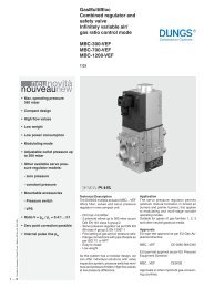
<strong>GasBloc</strong><br />
<strong>Multifunctional</strong> <strong>gas</strong> <strong>control</strong><br />
<strong>Combined</strong> <strong>regulator</strong> <strong>and</strong><br />
<strong>safety</strong> shut-off valves<br />
Integrated <strong>gas</strong>-air system<br />
GB-GD 055 D01<br />
Zero pressure <strong>regulator</strong><br />
GB-ND 055 D01<br />
3.03<br />
Printed in Germany • Rösler Druck • Edition 02.08 • Nr. 240 425<br />
1 … 6<br />
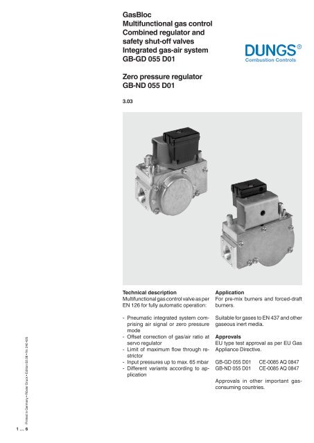
Technical description<br />
<strong>Multifunctional</strong> <strong>gas</strong> <strong>control</strong> valve as per<br />
EN 126 for fully automatic operation:<br />
- Pneumatic integrated system comprising<br />
air signal or zero pressure<br />
mode<br />
- Offset correction of <strong>gas</strong>/air ratio at<br />
servo <strong>regulator</strong><br />
- Limit of maximum flow through restrictor<br />
- Input pressures up to max. 65 mbar<br />
- Different variants according to application<br />
Application<br />
For pre-mix burners <strong>and</strong> forced-draft<br />
burners.<br />
Suitable for <strong>gas</strong>es to EN 437 <strong>and</strong> other<br />
<strong>gas</strong>eous inert media.<br />
Approvals<br />
EU type test approval as per EU Gas<br />
Appliance Directive.<br />
GB-GD 055 D01 CE-0085 AQ 0847<br />
GB-ND 055 D01 CE-0085 AQ 0847<br />
Approvals in other important <strong>gas</strong>consuming<br />
countries.
Combinations<br />
<strong>Multifunctional</strong> <strong>gas</strong> <strong>control</strong> valve GB-GD 055 D01 und GB-ND 055 D01<br />
Specification<br />
Main types<br />
Servo-pressure<br />
<strong>control</strong>ler<br />
Operating valve<br />
Solenoid valve<br />
[class]<br />
Safety valve<br />
Solenoid valve<br />
[class]<br />
<strong>Combined</strong> <strong>gas</strong>/air<br />
<strong>regulator</strong> 1:1<br />
Zero pressure<br />
<strong>regulator</strong><br />
Maximum<br />
restrictor<br />
Offset correction<br />
Gas pressure<br />
switch<br />
Start <strong>gas</strong> setting<br />
Line socket<br />
MPA 109x<br />
GB-GD 055 D01<br />
GB-ND 055 D01<br />
B<br />
B<br />
B<br />
B<br />
st<strong>and</strong>ard optional not available<br />
Type key of Gasbloc<br />
GB- XXXXX XXX DXX SXX<br />
Solenoid valve modes<br />
V1 <strong>and</strong> V2 can be activated <strong>and</strong> opened<br />
either together or separately.<br />
Control of V1 <strong>and</strong> V2<br />
0 = common<br />
2 = separated<br />
Outlet pressure Inlet pressure<br />
0 = 0 mbar bis 65 mbar<br />
2 = 1,5 - 20 mbar bis 65 mbar<br />
4 = 3 - 40 mbar bis 65 mbar<br />
S = Series (type-independent)<br />
Gas train schematic diagram<br />
1 = two class B solenoid valves with pressure <strong>regulator</strong><br />
2 = two class B solenoid valves without pressure <strong>regulator</strong><br />
Valve design<br />
0 = Double valve<br />
1 = Single valve, right angle<br />
2 = Single valve, straight<br />
Design type (generation) D<br />
Construction size, nominal diameter<br />
05 = p max. = 65 mbar<br />
3 = Rp 1/4<br />
5 = Rp 1/2<br />
7 = Rp 3/4<br />
Opening behaviour + main volume restrictor<br />
without = fast-opening, fast-closing<br />
-L = slow-opening<br />
-E = adjustable start <strong>gas</strong><br />
-P = pilot<strong>gas</strong> connection<br />
-G = Gas/Air ratio<br />
-D = main flow setting<br />
-N = Zero-Governor<br />
-M = electrical modulating type<br />
-W = Whirlwind version<br />
-Z = two stage<br />
<strong>GasBloc</strong><br />
Description of main components<br />
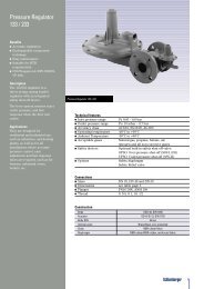
Pressure <strong>regulator</strong><br />
The pressure <strong>regulator</strong> includes a servo<br />
<strong>regulator</strong> to regulate pressure fluctuations<br />
in the mains supply. This ensures<br />
a precise volume flow <strong>and</strong> constant<br />
injector pressure.<br />
In the combined <strong>gas</strong>/air valve GB-GD<br />
055 the injector pressure follows the<br />
signal pressure applied to the servo<br />
diaphragm at a ratio of 1:1.<br />
The zero pressure valve GB-ND regulates<br />
the injector pressure at the valve<br />
outlet dependent on the vacuum generated,<br />
towards zero.<br />
Solenoid valves<br />
Solenoid valves as per EN 161, Class<br />
B. DC coils are protected against voltage<br />
transients.<br />
Filter<br />
Fine-meshed strainer to protect fitting.<br />
Pilot <strong>gas</strong><br />
Pilot <strong>gas</strong> connection between V1 <strong>and</strong><br />
V2.<br />
Gas pressure switch<br />
Optional equipment<br />
Monitors <strong>gas</strong> pressure on the inlet side<br />
for <strong>gas</strong> leakage protection. The pressure<br />
switch can be pre-adjusted <strong>and</strong><br />
sealed to customer specifications.<br />
Pressure instrument gl<strong>and</strong>s<br />
On inlet <strong>and</strong> outlet sides<br />
Block diagram<br />
A Filter<br />
B Automatic shut-off valves<br />
C Pressure <strong>regulator</strong><br />
D Servo-pressure <strong>regulator</strong><br />
E Start <strong>gas</strong> setting<br />
p 1<br />
Test nipple, inlet<br />
p 2<br />
Test nipple, outlet<br />
GB-GD<br />
A<br />
GB-ND<br />
P1<br />
B B D<br />
C<br />
V1<br />
V2<br />
P L<br />
E<br />
P amb<br />
B B D<br />
C<br />
V1<br />
A<br />
P1<br />
V1<br />
V2<br />
P2 E<br />
2 … 6
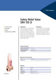
Functional diagram GB-GD 055 D01 / GB-ND 055 D01<br />
Legend<br />
15<br />
14<br />
13<br />
12<br />
11<br />
p 2<br />
7<br />
5<br />
6<br />
4<br />
3<br />
2<br />
1<br />
p 1<br />
V1<br />
V2<br />
p 2<br />
10<br />
16<br />
9<br />
8<br />
1 Fine-meshed strainer<br />
2 Housing<br />
3 Valve V1<br />
4 Closing spring<br />
5 Plunger V1<br />
6 Test nipple<br />
7 Solenoid V1<br />
8 Valve V2<br />
9 Main flow restrictor<br />
10 Solenoid V2<br />
11 Working diaphragm<br />
12 Return spring<br />
13 Operating valve<br />
14 Electrical connection<br />
15 Servo-pressure <strong>regulator</strong><br />
16 Connection for signal (only GB-GD...)<br />
Adjustment range<br />
Offset <strong>and</strong> <strong>gas</strong>/air ratio<br />
GB-GD integrated <strong>gas</strong>/air system<br />
P2<br />
P2<br />
V = 1<br />
Offset correction<br />
adjustment range<br />
GB-GD ± 0,2 mbar<br />
Offset correction<br />
adjustment range<br />
GB-GD<br />
V = 0,45<br />
Offset correction<br />
PL<br />
Main flow restrictor<br />
PL<br />
GB-ND zero pressure<br />
P2<br />
Adjustment instructions<br />
Offset correction<br />
adjustment range<br />
GB-ND ± 0,2 mbar<br />
Rapid <strong>and</strong> simple adjustment by<br />
means of:<br />
PL<br />
• Adjust offset correction using set<br />
ting screw on servo <strong>regulator</strong>.<br />
• Adjust maximum flow using flowrestriction<br />
screw.<br />
Offset correction<br />
3 … 6
Dimensions [mm]<br />
Electrical connection<br />
58<br />
ø 9<br />
4 x M4 - 7 deep<br />
Rp 1/2 ISO 7/1<br />
102<br />
40,5<br />
St<strong>and</strong>ard<br />
Box with cable connection IP 40<br />
Molex Crimp System 3001<br />
12,5<br />
12,5<br />
30,5<br />
24<br />
ø 55<br />
34<br />
15,4<br />
28 58<br />
24<br />
60<br />
34<br />
8,4<br />
18,9<br />
105<br />
Adjusting devices<br />
Pressure <strong>regulator</strong><br />
offset adjustment<br />
Solenoid coils<br />
Pressure test<br />
nipple P 2<br />
Maximum restrictor<br />
Pressure test nipple P 1<br />
Volume flow pressure difference characteristic<br />
GB-(LEP) 055 D01 - pneumatic to DIN EN 126<br />
Inlet pressure range (mbar)<br />
2nd <strong>gas</strong> family<br />
Natural <strong>gas</strong>-H-E<br />
Natural <strong>gas</strong>-L<br />
P NOM.<br />
20<br />
25<br />
P MAX.<br />
25<br />
30<br />
P MIN.<br />
17<br />
20<br />
<br />
<br />
<br />
<br />
<br />
<br />
<br />
<br />
Permissible deviation<br />
Pressure <strong>regulator</strong> class C - 2nd <strong>gas</strong><br />
family<br />
p 2<br />
+ 10 % - 15 % as per EN 126<br />
<br />
<br />
<br />
<br />
<br />
<br />
<br />
<br />
<br />
<br />
<br />
<br />
<br />
<br />
<br />
<br />
<br />
<br />
<br />
<br />
<br />
<br />
<br />
<br />
<br />
<br />
<br />
<br />
<br />
<br />
<br />
4 … 6
Volume flow pressure difference characteristic<br />
<br />
GB-..... 055 D01 - pneumatic to DIN EN 126<br />
Inlet pressure range (mbar) <br />
3rd <strong>gas</strong> family<br />
Propane<br />
P NOM.<br />
37<br />
Permissible deviation<br />
Pressure <strong>regulator</strong> class C - 3rd <strong>gas</strong><br />
family<br />
p 2<br />
±10 % as per EN 126<br />
<br />
<br />
<br />
<br />
<br />
<br />
<br />
<br />
P<br />
<br />
MAX.<br />
45<br />
<br />
<br />
25<br />
<br />
P<br />
<br />
MIN.<br />
Volume flow pressure difference characteristic<br />
GB-..... 055 D01 - pneumatic to DIN EN 126<br />
Inlet pressure range (mbar)<br />
3rd <strong>gas</strong> family<br />
Butane/Propane<br />
P NOM.<br />
50<br />
Permissible deviation<br />
Pressure <strong>regulator</strong> class C - 3rd <strong>gas</strong><br />
family<br />
p 2<br />
±10 % as per EN 126<br />
P MAX.<br />
57,5<br />
P MIN.<br />
42,5<br />
<br />
<br />
<br />
<br />
<br />
<br />
<br />
<br />
<br />
<br />
<br />
<br />
<br />
<br />
<br />
<br />
<br />
<br />
<br />
<br />
<br />
<br />
<br />
<br />
<br />
<br />
<br />
<br />
<br />
<br />
<br />
<br />
<br />
<br />
<br />
<br />
<br />
<br />
<br />
<br />
<br />
<br />
<br />
<br />
<br />
<br />
<br />
<br />
<br />
<br />
<br />
<br />
<br />
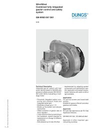
Volume flow pressure difference characteristic<br />
GB-..... 055 D01 - pneumatic to DIN EN 126<br />
<br />
<br />
<br />
<br />
<br />
<br />
<br />
<br />
<br />
<br />
<br />
<br />
<br />
<br />
<br />
<br />
<br />
<br />
<br />
<br />
<br />
<br />
<br />
<br />
<br />
<br />
<br />
<br />
<br />
<br />
<br />
<br />
<br />
100<br />
80<br />
60<br />
50<br />
40<br />
recommended work range<br />
30<br />
∆p [mbar]<br />
20<br />
10<br />
8<br />
6<br />
5<br />
4<br />
3<br />
2<br />
Based on + 15° C, 1013 mbar, dry<br />
1<br />
0,1 0,2 0,3 0,4 0,5 0,6 0,8 1 2 3 4 5 6 7 8 910 20<br />
Vn ° 3<br />
[m /h] Luft / Air / Aria dv = 1,00<br />
0,2 0,3 0,4 0,50,6 0,8 1 2 3 4 5 6 7 8 910 20 30<br />
Vn °<br />
3<br />
[m /h] Erd<strong>gas</strong>/Natural <strong>gas</strong>/Gaz Naturel/Gas metano dv = 0,65<br />
5 … 6
<strong>GasBloc</strong><br />
<strong>Multifunctional</strong> <strong>gas</strong> <strong>control</strong><br />
<strong>Combined</strong> <strong>regulator</strong> <strong>and</strong> <strong>safety</strong><br />
shut-off valves<br />
Integrated <strong>gas</strong>-air system<br />
GB-GD 055 D01<br />
Zero pressure <strong>regulator</strong><br />
GB-ND 055 D01<br />
Specifications Nominal diameter<br />
DN 15<br />
Gas connection<br />
Rp 1/2<br />
G 3/4<br />
ISO 7/1<br />
DIN ISO 228 OD<br />
Flange with tube thread<br />
Rp 1/2<br />
G 3/4<br />
ISO 7/1 ID<br />
DIN ISO 228 OD<br />
Max. inlet pressure<br />
Nominal flow GB-GD 055<br />
Nominal flow GB-ND 055<br />
Ambient temperature<br />
Automatic shut-off valves<br />
Group<br />
Pressure <strong>regulator</strong><br />
Proportional adjustment range V<br />
Minimum signal pressure<br />
Offset correction<br />
Degree of protection<br />
Opening time<br />
Closing time<br />
Switch on duration<br />
Voltage/frequency<br />
Load of coil (24 V, 230 V)<br />
Electrical connection<br />
Optional equipment<br />
Installation position<br />
65 mbar<br />
3.3m 3 /h (air) at ∆p 5 mbar, regulated<br />
7,2 m 3 /h (air) at ∆p 30 mbar, regulated<br />
-15 °C to +70 °C<br />
0 °C to 70 °C at LPG<br />
Class B as per EN 126<br />
2<br />
Class C<br />
V = p <strong>gas</strong><br />
- p air<br />
= 0,45-1<br />
0,3 mbar at ∆p Offset<br />
= 0 Pa<br />
± 0,2 mbar<br />
IP 40<br />
Fast-opening < 1 s<br />
Slow-opening < 10 s<br />
< 1 s<br />
100 % ED<br />
~(AC) 50 - 60 Hz 24 V +10 % – 15 %<br />
~(AC) 50 - 60 Hz 230 V +10 % – 15 %<br />
2 x 5,5 VA<br />
Molex System connection coil or<br />
Option: Connection box with integrated<br />
cable<br />
Electrical connections in Rast 5<br />
Automatic burner <strong>control</strong> MPA 109x<br />
Gas pressure switch GW A5<br />
Solenoid at any position between vertical<br />
<strong>and</strong> horizontal axis.<br />
We reserve the right to make any changes in the interest of technical progress.<br />
Head Offices <strong>and</strong> Factory<br />
Karl Dungs GmbH & Co. KG<br />
Siemensstraße 6-10<br />
D-73660 Urbach, Germany<br />
Telefon +49 (0)7181-804-0<br />
Telefax +49 (0)7181-804-166<br />
Postal adress<br />
Karl Dungs GmbH & Co. KG<br />
Postfach 12 29<br />
D-73602 Schorndorf, Germany<br />
e-mail info@dungs.com<br />
Internet www.dungs.com<br />
6 … 6