12V Diesel Transfer Pump - Harbor Freight Tools
12V Diesel Transfer Pump - Harbor Freight Tools
12V Diesel Transfer Pump - Harbor Freight Tools

You also want an ePaper? Increase the reach of your titles
YUMPU automatically turns print PDFs into web optimized ePapers that Google loves.
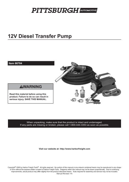
<strong>12V</strong> <strong>Diesel</strong> <strong>Transfer</strong> <strong>Pump</strong><br />
Item 66784<br />
Read this material before using this<br />
product. Failure to do so can result in<br />
serious injury. SAVE THIS MANUAL.<br />
When unpacking, make sure that the product is intact and undamaged.<br />
If any parts are missing or broken, please call 1-800-444-3353 as soon as possible.<br />
Visit our website at: http://www.harborfreight.com<br />
Copyright © 2009 by <strong>Harbor</strong> <strong>Freight</strong> <strong>Tools</strong> ® . All rights reserved. No portion of this manual or any artwork contained herein may be reproduced in any shape<br />
or form without the express written consent of <strong>Harbor</strong> <strong>Freight</strong> <strong>Tools</strong>. Diagrams within this manual may not be drawn proportionally. Due to continuing<br />
improvements, actual product may differ slightly from the product described herein. <strong>Tools</strong> required for assembly and service may not be included.<br />
Manual Revised 11h
Save This Manual<br />
Keep this manual for the safety warnings and<br />
precautions, assembly, operating, inspection,<br />
maintenance and cleaning procedures. Write the<br />
product’s serial number in the back of the manual near<br />
the assembly diagram (or month and year of purchase<br />
if product has no number). Keep this manual and the<br />
receipt in a safe and dry place for future reference.<br />
Safety Alert Symbol<br />
and Signal Words<br />
In this manual, on the labeling, and all other<br />
information provided with this product:<br />
This is the safety alert symbol. It is<br />
used to alert you to potential personal<br />
injury hazards. Obey all safety<br />
messages that follow this symbol<br />
to avoid possible injury or death.<br />
DANGER indicates a hazardous situation which, if<br />
not avoided, will result in death or serious injury.<br />
WARNING indicates a hazardous situation which, if<br />
not avoided, could result in death or serious injury.<br />
CAUTION, used with the safety alert symbol,<br />
indicates a hazardous situation which, if not<br />
avoided, could result in minor or moderate injury.<br />
NOTICE is used to address practices<br />
not related to personal injury.<br />
CAUTION, without the safety alert symbol, is used<br />
to address practices not related to personal injury.<br />
IMPORTANT SAFETY<br />
INSTRUCTIONS<br />
INSTRUCTIONS PERTAINING TO A<br />
RISK OF FIRE, ELECTRIC SHOCK,<br />
OR INJURY TO PERSONS<br />
WARNING – When using pumps, basic precautions<br />
should always be followed, including the following:<br />
Work Area<br />
a. Keep the work area clean and well lighted.<br />
Cluttered or dark areas increase the risks of<br />
electric shock, fire, and injury to persons.<br />
b. Do not operate pumps in explosive<br />
atmospheres, such as in the presence of<br />
flammable liquids, gases or dust. <strong>Pump</strong>s create<br />
sparks which may ignite the dust or fumes.<br />
c. Keep bystanders, children, and visitors away<br />
while operating the pump. Distractions are able<br />
to result in the loss of control of the pump.<br />
Electrical Safety<br />
a. Do not expose pumps to rain or wet<br />
conditions. Water entering a pump will<br />
increase the risk of electric shock.<br />
b. Do not abuse the Power Cables. Never use<br />
the cables for carrying or pulling the pump.<br />
Keep cables away from heat, oil, sharp edges<br />
or moving parts. Damaged or entangled<br />
cables increase the risk of electric shock.<br />
Personal Safety<br />
a. Stay alert, watch what you are doing and<br />
use common sense when operating a pump.<br />
Do not use a pump while you are tired or under<br />
the influence of drugs, alcohol or medication.<br />
A moment of inattention while operating pumps<br />
may result in serious personal injury.<br />
b. Prevent unintentional starting. Ensure<br />
the switch is in the off-position before<br />
connecting to the power supply.<br />
c. Do not overreach. Keep proper<br />
footing and balance at all times.<br />
Proper footing and balance enables better<br />
control of the pump in unexpected situations.<br />
d. Use safety equipment. A dust mask,<br />
non‐skid safety shoes and a hard hat must<br />
be used for the applicable conditions.<br />
e. Wear ANSI‐approved safety goggles<br />
during setup and use.<br />
f. Dress properly. Do not wear loose clothing or<br />
jewelry. Keep your hair, clothing and gloves<br />
away from moving parts. Loose clothes, jewelry<br />
or long hair can be caught in moving parts.<br />
<strong>Pump</strong> Use and Care<br />
a. Do not force the pump. Use the correct pump for<br />
your application. The correct pump will do the job<br />
better and safer at the rate for which it was designed.<br />
Page 2 For technical questions, please call 1-800-444-3353. SKU 66784
. Do not use the pump if the switch does not turn<br />
it on and off. Any pump that cannot be controlled<br />
with the switch is dangerous and must be repaired.<br />
c. Disconnect the Cables from the power<br />
supply before making any adjustments,<br />
changing accessories, or storing pumps.<br />
Such preventive safety measures reduce the<br />
risk of starting the pump accidentally.<br />
d. Store idle pumps out of the reach of children and<br />
do not allow persons unfamiliar with the pump or<br />
these instructions to operate the pump. <strong>Pump</strong>s<br />
are dangerous in the hands of untrained users.<br />
e. Maintain pumps. Check for misalignment or<br />
binding of moving parts, breakage of parts<br />
and any other condition that may affect<br />
the pump’s operation. If damaged, have the<br />
pump repaired before use. Many accidents<br />
are caused by poorly maintained pumps.<br />
f. Use the pump, accessories and pump bits<br />
etc. in accordance with these instructions,<br />
taking into account the working conditions<br />
and the work to be performed. Use of<br />
the pump for operations different from those<br />
intended could result in a hazardous situation.<br />
Battery Precautions<br />
a. Under abusive conditions, liquid may be<br />
ejected from the battery. Avoid contact.<br />
If contact accidentally occurs, flush with<br />
water. If liquid contacts eyes, additionally<br />
seek medical help. Liquid ejected from the<br />
battery may cause irritation or burns.<br />
Service<br />
a. <strong>Pump</strong> service must be performed only<br />
by qualified repair personnel, using<br />
only identical replacement parts.<br />
Specific Safety Instructions<br />
1. This <strong>Pump</strong> is designed for use with diesel fuel or<br />
kerosene only. Not for use with fluids that have a<br />
flash point below 100° F (i.e., gasoline, alcohol).<br />
2. Maintain labels and nameplates on<br />
the <strong>Pump</strong>. These carry important safety<br />
information. If unreadable or missing, contact<br />
<strong>Harbor</strong> <strong>Freight</strong> <strong>Tools</strong> for a replacement.<br />
3. Never smoke near the <strong>Pump</strong> or use<br />
the <strong>Pump</strong> near an open flame.<br />
4. Do not use for fluid transfer into or from aircraft.<br />
5. This product is not designed for use with medical<br />
products, water, or fluids for human consumption.<br />
6. Anchor the barrel or tank (not included)<br />
to prevent tipping.<br />
7. Do not use while on a motorized vehicle<br />
while the engine is running.<br />
8. Avoid unintentional starting. Prepare to<br />
begin work before turning on the <strong>Pump</strong>.<br />
9. When using a handheld pump, maintain<br />
a firm grip on the pump with both<br />
hands to resist starting torque.<br />
10. Do not leave the <strong>Pump</strong> unattended<br />
when it is connected to a power supply.<br />
Turn off the pump, and disconnect it from<br />
its power supply before leaving.<br />
11. This product is not a toy. Keep<br />
it out of reach of children.<br />
12. People with pacemakers should consult their<br />
physician(s) before use. Electromagnetic fields<br />
in close proximity to heart pacemaker could<br />
cause pacemaker interference or pacemaker<br />
failure. In addition, people with pacemakers should:<br />
• Avoid operating alone.<br />
• Do not use with power switch locked on.<br />
• Properly maintain and inspect<br />
to avoid electrical shock.<br />
13. WARNING: Handling the cord on this product will<br />
expose you to lead, a chemical known to the State of<br />
California to cause cancer, and birth defects or other<br />
reproductive harm. Wash hands after handling.<br />
(California Health & Safety Code § 25249.5, et seq.)<br />
The brass components of this product contain lead,<br />
a chemical known to the State of California to cause<br />
birth defects.<br />
(California Health & Safety Code § 25249.5, et seq.)<br />
14. The warnings, precautions, and instructions<br />
discussed in this instruction manual cannot<br />
cover all possible conditions and situations<br />
that may occur. It must be understood by the<br />
operator that common sense and caution are<br />
factors which cannot be built into this product,<br />
but must be supplied by the operator.<br />
SAVE THESE<br />
INSTRUCTIONS.<br />
SKU 66784<br />
For technical questions, please call 1-800-444-3353.<br />
Page 3
Functional Description<br />
*Duty Cycle (Duration of Use)<br />
Specifications<br />
Product<br />
Applications<br />
Only use with diesel fuel or<br />
kerosene.<br />
Do not use with gasoline,<br />
alcohol, water, corrosive<br />
chemicals, solvents, or<br />
liquids that have a flash<br />
point below 100° F.<br />
Electrical Input <strong>12V</strong>DC / 13.5A<br />
Fuse<br />
Motor<br />
<strong>Pump</strong><br />
Operating Conditions<br />
Hose Size<br />
Thermal Overload<br />
Protection<br />
25A (included)<br />
30 Minute Duty Cycle*<br />
2800 RPM<br />
Self-Priming, Volumetric,<br />
Rotating Vane,<br />
with Bypass Valve<br />
Inlet/Outlet: 3/4″ Female NPT<br />
Lift: 6.6 Feet<br />
Flow Rate: 10 GPM<br />
-4° – 140° F<br />
up to 90% Relative Humidity<br />
0.75 IN. I.D., 1.125 IN. O.D.,<br />
13 FT. Long<br />
Yes<br />
30 Minute Duty Cycle<br />
30 minutes welding<br />
followed by<br />
at least 30 minutes of rest<br />
Avoid damage to the <strong>Pump</strong> by not pumping for<br />
more than the prescribed duty cycle time. The Duty<br />
Cycle defines the number of minutes, within a one hour<br />
period, during which a given pump can pump without<br />
overheating. For example, this <strong>Pump</strong> with a 30 minute<br />
duty cycle must be allowed to rest for at least 30 minutes<br />
after every 30 minutes of use. Failure to carefully<br />
observe duty cycle limitations can easily over‐stress<br />
a pump contributing to premature pump failure.<br />
This pump has an internal thermal protection system<br />
to help prevent this sort of over-stress. When the<br />
unit overheats, it automatically shuts down, then it<br />
automatically begins pumping again after cooling off.<br />
When the pump can be used again, use shorter pumping<br />
periods and longer rest periods to prevent needless wear.<br />
Page 4 For technical questions, please call 1-800-444-3353. SKU 66784
Assembly<br />
Read the ENTIRE IMPORTANT<br />
SAFETY INFORMATION section at the<br />
beginning of this manual including<br />
all text under subheadings therein<br />
before set up or use of this product.<br />
TO PREVENT SERIOUS INJURY<br />
FROM ACCIDENTAL OPERATION:<br />
Disconnect the <strong>Pump</strong> from its power<br />
supply before assembly/installation.<br />
Note: For additional information regarding the<br />
parts listed in the following pages, refer to the<br />
Assembly Diagram near the end of this manual.<br />
Note: Pipe thread seal tape mentioned<br />
hereafter is not supplied with this pump.<br />
1. Cut the supplied hose, into two lengths, keeping<br />
in mind that the suction end should be long<br />
enough to reach within one inch of the supply<br />
tank bottom and at the same time to be long<br />
enough so that the <strong>Pump</strong> could be located at<br />
a point away from the supply tank opening.<br />
3. Apply pipe thread seal tape to the threads<br />
of the 1″ Hose Connector (11) and screw<br />
it firmly into the Nozzle (12).<br />
Note: The included Hose (27) can be cut to<br />
provide an inlet and outlet hose, or another hose<br />
of the same size can be purchased as needed.<br />
Any hose used with this product must be<br />
designed for use with the liquid being pumped.<br />
4. Slide two Hose Clamps (10) onto the discharge<br />
Hose (27). Twist each end of the hose over<br />
the two barbed fittings and push forward<br />
until the hose ends presses firmly over the<br />
O-rings and against the fitting shoulder.<br />
5. Slide the Hose Clamps to within 3/8″ of<br />
the fitting shoulder and tighten the screws,<br />
securing the hose onto the fittings.<br />
6. Apply pipe thread seal tape to the threads<br />
of one 3/4″ Hose Connector (8) and<br />
screw it firmly into the <strong>Pump</strong> inlet.<br />
PUMP<br />
INLET<br />
3/4″ HOSE<br />
CONNECTOR<br />
(11)<br />
HOSE<br />
CLAMP (10)<br />
FIGURE A<br />
NOZZLE<br />
(12)<br />
HOSE (27)<br />
HOSE<br />
CONNECTOR<br />
(11)<br />
HOSE<br />
CLAMP<br />
(10)<br />
HOSE<br />
(27)<br />
PUMP<br />
OUTLET<br />
FIGURE B<br />
HOSE<br />
CLAMP (10)<br />
STRAINER<br />
(33)<br />
HOSE<br />
CLAMP (10)<br />
HOSE<br />
CONNECTOR<br />
(8)<br />
2. Apply pipe thread seal tape to the threads<br />
of one 3/4″ Hose Connector (8) and<br />
screw it firmly into the <strong>Pump</strong> outlet.<br />
7. Slide two Hose Clamps (10) onto the inlet Hose<br />
(27). Twist one end of the hose over the pump<br />
inlet barbed fitting and the other end over the<br />
barbed fitting on the strainer. Push the hose<br />
forward until the hose ends presses firmly over<br />
the O-rings and against the fitting shoulders.<br />
8. Slide the Hose Clamps to within 3/8″ of<br />
the fitting shoulder and tighten the screws,<br />
securing the hose onto the fittings.<br />
SKU 66784<br />
For technical questions, please call 1-800-444-3353.<br />
Page 5
Operating Instructions<br />
Read the ENTIRE IMPORTANT<br />
SAFETY INFORMATION section at the<br />
beginning of this manual including<br />
all text under subheadings therein<br />
before set up or use of this product.<br />
Inspect pump before use, looking for<br />
damaged, loose, and missing parts.<br />
If any problems are found, do<br />
not use pump until repaired.<br />
<strong>Pump</strong> Set Up<br />
TO PREVENT SERIOUS INJURY<br />
FROM ACCIDENTAL OPERATION:<br />
Disconnect the <strong>Pump</strong> from its 12 volt power<br />
source before performing any inspection,<br />
maintenance, or cleaning procedures.<br />
1. Designate a work area that is clean and well‐lit.<br />
The work area must not allow access by children<br />
or pets to prevent distraction or injury.<br />
2. Route the Power Cables (16) along a safe route<br />
to reach the work area without creating a tripping<br />
hazard or exposing the cables to possible damage.<br />
The cables must reach the work area with enough<br />
extra length to allow free movement while working.<br />
3. There must not be hazardous objects, such<br />
as utility lines or foreign objects, nearby that<br />
will present a hazard while working.<br />
4. Have rags nearby to clean up any fuel spills.<br />
5. Have multiple fully charged ABC fire<br />
extinguishers nearby in case of fire.<br />
General Operating Instructions<br />
1. Connect the Cables with Clamps (16) to a 12 volt<br />
power supply (such as a battery, not included).<br />
Connect the RED Clamp to the Positive (+) terminal<br />
and the BLACK Clamp to the Negative (-) terminal.<br />
2. Insert the Nozzle (12) into the destination tank.<br />
3. Insert the Hose (27) with its Strainer (33) into the fuel<br />
supply tank. Immerse the Strainer in the fuel fully.<br />
4. Press the Power Switch (15) to start the <strong>Pump</strong>.<br />
5. Squeeze trigger of the Nozzle (12) to<br />
discharge fuel into the destination tank.<br />
Hold the Nozzle firmly during the fuel transfer.<br />
6. To reduce hand fatigue during extended pumping,<br />
lock the Trigger in one of the two positions by lifting<br />
and positioning the spring loaded trigger lock into one<br />
of the two recessed steps under the trigger.<br />
Ease back on trigger to lock it in place.<br />
To stop pumping, pull slightly on the<br />
trigger to release the lock.<br />
7. When the fuel has been transferred,<br />
release pressure on the Nozzle (12) Trigger.<br />
When fuel stops flowing, turn off the <strong>Pump</strong>.<br />
8. Disconnect the Cables with Clamps (16) black<br />
first, then red, from the 12 volt power supply.<br />
9. Remove the Nozzle from the destination<br />
tank and place in a secure location.<br />
10. Remove the Hose (27) with its Strainer (33)<br />
from the fuel supply tank, allowing fuel to<br />
drain out of the Hose before removing it.<br />
11. Cap both supply and the destination<br />
tanks to prevent fuel spills.<br />
12. Clean and dry all exterior parts of the <strong>Pump</strong> Body (6),<br />
Hose (27), Nozzle (12), and Cables with Clamps (16).<br />
13. Store the <strong>Pump</strong> indoors and out of reach of<br />
children and other unauthorized persons.<br />
Page 6 For technical questions, please call 1-800-444-3353. SKU 66784
User‐Maintenance Instructions<br />
Procedures not specifically explained<br />
in this manual must be performed<br />
only by a qualified technician.<br />
TO PREVENT SERIOUS INJURY<br />
FROM ACCIDENTAL OPERATION:<br />
Disconnect the <strong>Pump</strong> from its 12 volt power<br />
source before performing any inspection,<br />
maintenance, or cleaning procedures.<br />
TO PREVENT SERIOUS INJURY<br />
FROM PUMP FAILURE:<br />
Do not use damaged equipment.<br />
If abnormal noise, vibration, or leaking air occurs,<br />
have the problem corrected before further use.<br />
1. BEFORE EACH USE, inspect the general condition<br />
of the <strong>Pump</strong>. Check for loose screws, misalignment<br />
or binding of moving parts, cracked or broken<br />
parts, damaged electrical wiring, hoses, and any<br />
other condition that may affect its safe operation.<br />
2. TO REPLACE THE FUSE:<br />
a. Disconnect the Cables from<br />
the <strong>12V</strong> power source.<br />
b. Open the Fuse Holder on the Cable (16).<br />
c. Remove the Fuse (13) by pulling it straight out<br />
of the Fuse Holder. Then press in a new Fuse<br />
of the same type, size, and rating (25A).<br />
d. Close the Fuse Holder on the Cable (16)<br />
3. AFTER USE, clean external surfaces<br />
of the pump with clean cloth.<br />
Troubleshooting<br />
Problem Possible Causes Likely Solutions<br />
<strong>Pump</strong> will not start. 1. Battery is dead or discharged.<br />
1. Check battery power.<br />
<strong>Pump</strong> will not operate<br />
or pumps fuel in<br />
wrong direction.<br />
Poor fuel transfer.<br />
2. Clamps are not properly connected.<br />
3. Fuse burned out.<br />
Clamps are connected in wrong polarity.<br />
1. Intake hose is not submerged in fuel<br />
or supply tank is low or empty.<br />
2. Clogged Strainer.<br />
3. Kinked hoses.<br />
4. Hoses are leaking.<br />
5. Hoses or handle is clogged.<br />
2. Make sure clamps are securely connected.<br />
3. Replace with new fuse.<br />
Reverse clamps.<br />
(Red clamp on positive (+) terminal.<br />
Black clamp on negative (–) terminal).<br />
1. Check intake hose and supply tank.<br />
2. Wash/replace Strainer.<br />
3. Straighten Hose.<br />
4. Check hoses for leaks and repair or replace.<br />
5. Check and clean hoses and handle.<br />
Follow all safety precautions whenever diagnosing or servicing the pump.<br />
Disconnect air supply before service.<br />
SKU 66784<br />
For technical questions, please call 1-800-444-3353.<br />
Page 7
Parts List and Assembly Diagram<br />
PLEASE READ THE FOLLOWING CAREFULLY<br />
THE MANUFACTURER AND/OR DISTRIBUTOR HAS PROVIDED THE PARTS LIST AND ASSEMBLY DIAGRAM<br />
IN THIS MANUAL AS A REFERENCE TOOL ONLY. NEITHER THE MANUFACTURER OR DISTRIBUTOR<br />
MAKES ANY REPRESENTATION OR WARRANTY OF ANY KIND TO THE BUYER THAT HE OR SHE IS<br />
QUALIFIED TO MAKE ANY REPAIRS TO THE PRODUCT, OR THAT HE OR SHE IS QUALIFIED TO REPLACE<br />
ANY PARTS OF THE PRODUCT. IN FACT, THE MANUFACTURER AND/OR DISTRIBUTOR EXPRESSLY<br />
STATES THAT ALL REPAIRS AND PARTS REPLACEMENTS SHOULD BE UNDERTAKEN BY CERTIFIED AND<br />
LICENSED TECHNICIANS, AND NOT BY THE BUYER. THE BUYER ASSUMES ALL RISK AND LIABILITY<br />
ARISING OUT OF HIS OR HER REPAIRS TO THE ORIGINAL PRODUCT OR REPLACEMENT PARTS<br />
THERETO, OR ARISING OUT OF HIS OR HER INSTALLATION OF REPLACEMENT PARTS THERETO.<br />
Parts List<br />
Part Description Qty.<br />
1 Screw (M5×10) 8<br />
2 Front Cover 1<br />
3 O-Ring 1<br />
4 Rotor 1<br />
5 Blade 5<br />
6 <strong>Pump</strong> Body 1<br />
7 Bypass Valve 1<br />
8 3/4″ Male Hose Connector 2<br />
9 Handle 1<br />
10 Hose Clamp 4<br />
11 1″ Hose Connector 1<br />
12 Nozzle 1<br />
13 Fuse (25A) 1<br />
15 Power Switch 1<br />
16 Cables with Clamps and Fuse Holder 1<br />
Part Description Qty.<br />
17 Terminal Board 1<br />
18 Screw (M4×15) 2<br />
19 Compression Nut 1<br />
20 Tapered Ring 1<br />
21 Nut (M5) 2<br />
22 Terminal 2<br />
23 12 VDC Motor 1<br />
24 Bearing 2<br />
25 Spring Collar 1<br />
26 Seal 1<br />
27 Hose 1<br />
30 Bypass Spring 1<br />
31 Base 1<br />
32 Key 1<br />
33 Strainer 1<br />
Record Product’s Serial Number Here:<br />
Note: If product has no serial number, record month and year of purchase instead.<br />
Note: Some parts are listed and shown for illustration purposes only,<br />
and are not available individually as replacement parts.<br />
Page 8 For technical questions, please call 1-800-444-3353. SKU 66784
Assembly Diagram<br />
SKU 66784<br />
For technical questions, please call 1-800-444-3353.<br />
Page 9
90 Day Warranty<br />
<strong>Harbor</strong> <strong>Freight</strong> <strong>Tools</strong> Co. makes every effort to assure that its products meet high quality and durability standards,<br />
and warrants to the original purchaser that this product is free from defects in materials and workmanship for the<br />
period of 90 days from the date of purchase. This warranty does not apply to damage due directly or indirectly,<br />
to misuse, abuse, negligence or accidents, repairs or alterations outside our facilities, criminal activity, improper<br />
installation, normal wear and tear, or to lack of maintenance. We shall in no event be liable for death, injuries<br />
to persons or property, or for incidental, contingent, special or consequential damages arising from the use of<br />
our product. Some states do not allow the exclusion or limitation of incidental or consequential damages, so the<br />
above limitation of exclusion may not apply to you. THIS WARRANTY IS EXPRESSLY IN LIEU OF ALL OTHER<br />
WARRANTIES, EXPRESS OR IMPLIED, INCLUDING THE WARRANTIES OF MERCHANTABILITY AND FITNESS.<br />
To take advantage of this warranty, the product or part must be returned to us with transportation charges<br />
prepaid. Proof of purchase date and an explanation of the complaint must accompany the merchandise.<br />
If our inspection verifies the defect, we will either repair or replace the product at our election or we may<br />
elect to refund the purchase price if we cannot readily and quickly provide you with a replacement. We will<br />
return repaired products at our expense, but if we determine there is no defect, or that the defect resulted<br />
from causes not within the scope of our warranty, then you must bear the cost of returning the product.<br />
This warranty gives you specific legal rights and you may also have other rights which vary from state to state.<br />
Page 10 For technical questions, please call 1-800-444-3353. SKU 66784
Notes<br />
SKU 66784<br />
For technical questions, please call 1-800-444-3353.<br />
Page 11
3491 Mission Oaks Blvd. • PO Box 6009 • Camarillo, CA 93011 • (800) 444-3353