XR1267 - Xtreme Manufacturing
XR1267 - Xtreme Manufacturing
XR1267 - Xtreme Manufacturing

Create successful ePaper yourself
Turn your PDF publications into a flip-book with our unique Google optimized e-Paper software.
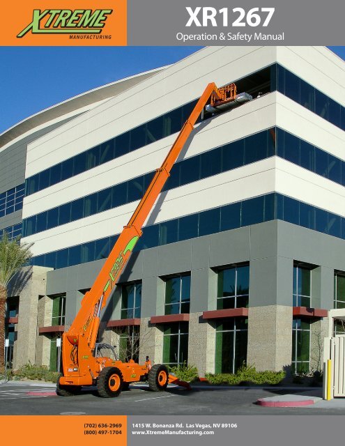
<strong>XR1267</strong><br />
Operation & Safety Manual<br />
(702) 636-2969<br />
(800) 497-1704<br />
1415 W. Bonanza Rd. Las Vegas, NV 89106<br />
www.<strong>Xtreme</strong><strong>Manufacturing</strong>.com
<strong>XR1267</strong><br />
Introduction . . . . . . . . . . . . . . . . . . . . . . . . . . . 3<br />
General . 3<br />
Replacement manuals . 3<br />
Model/Serial Number Plate. 3<br />
Orientation. 3<br />
Safety. . . . . . . . . . . . . . . . . . . . . . . . . . . . . . . . 4<br />
Safety Disclaimer . 4<br />
Signal Words. 4<br />
Safety Symbols . 4<br />
Employer Responsibility . 7<br />
Operator Responsibility. 7<br />
Operator Qualifications . 7<br />
Modifications . 7<br />
Mounting/Dismounting . 8<br />
Work Site Safety. 8<br />
Before Starting Forklift. 9<br />
Operation Safety . 10<br />
Load Safety. 13<br />
Attachments. 13<br />
Shut Down Procedure. 13<br />
Forklift Maintenance . 14<br />
Dead Engine Towing . . . . . . . . . . . . . . . . . . . . . 16<br />
Parking Brake Release (Front Axle) . 16<br />
Re-activating Parking Brakes (Front Axle). 16<br />
Labels. . . . . . . . . . . . . . . . . . . . . . . . . . . . . . . 18<br />
Label Legend . 18<br />
Left Side View. 18<br />
Right Side View. 18<br />
Front View . 19<br />
Rear View. 19<br />
Cab View. 19<br />
Replacement Labels . 21<br />
Features . . . . . . . . . . . . . . . . . . . . . . . . . . . . . 32<br />
Standard Equipment. 32<br />
Optional Equipment. 32<br />
Specifications. . . . . . . . . . . . . . . . . . . . . . . . . . 33<br />
Operator Cab . . . . . . . . . . . . . . . . . . . . . . . . . . 34<br />
Ignition Switch . 34<br />
Accessory Outlet. 34<br />
Accelerator Pedal. 34<br />
Service Brake Pedal. 35<br />
Steering Wheel . 35<br />
Horn Button. 35<br />
Operator Seat. 35<br />
Operator Seat Controls. 35<br />
Weight Suspension Lever. 35<br />
Lumbar Support. 36<br />
Fore and Aft Adjustment Lever. 36<br />
Backrest Angle Adjustment Lever. 36<br />
For information call (800) 497-1704<br />
Table of Contents<br />
Seat Belt. 36<br />
Rear View Mirrors. 37<br />
Controls and Indicators . 37<br />
Travel Select Lever. 37<br />
Gear Select Switch. 38<br />
Parking Brake Switch. 38<br />
Load Capacity Charts . 38<br />
Hydraulic Oil Temperature Indicator. 38<br />
Low Brake Pressure Indicator . 39<br />
Rear Axle Lock Indicator. 39<br />
Hourmeter . 39<br />
Voltage Gauge. 39<br />
Fuel Gauge. 40<br />
Oil Gauge. 40<br />
Coolant Gauge. . . . . . . . . . . . . . . . . . . . . . . . . 40<br />
Light Switches. 40<br />
Work Light Switch . 40<br />
Rear Axle Centering Indicator . 41<br />
Steering Select Switch. 41<br />
Declutch Indicator. 41<br />
Declutch Switch. 41<br />
Outrigger Toggle Switches. 42<br />
Boom Control. 42<br />
Attachment Tilt Switch . 44<br />
Frame Sway Control Handle . 44<br />
Auxiliary Attachment Control. 45<br />
Optional Controls and Indicators. 45<br />
Two Wheel Rear (2WR) Steering Switch . 45<br />
Boom Angle Indicator. 46<br />
Boom Extend Letters. 46<br />
Frame Level Indicator . 46<br />
Operation . . . . . . . . . . . . . . . . . . . . . . . . . . . . 47<br />
Pre-Operation Inspection. 47<br />
Pre-Operation Inspection Checklist . 49<br />
Functional Tests. 50<br />
Functional Test Checklist. 50<br />
Operator Maintenance . 51<br />
Before Starting Forklift. 52<br />
Starting Forklift . 52<br />
Normal Starting. 53<br />
Cold Starting. 53<br />
Jump Starting . 54<br />
Forklift Travel. 55<br />
Steering Modes . 55<br />
Crab Steering. 55<br />
Two Wheel Steering (2W). 55<br />
Four Wheel Steering (4W) . 55<br />
Two Wheel Rear Steering (2WR) (Optional). 55<br />
Maximum Fork Sweep. 55<br />
Starting Travel. 56<br />
Shifting Gears . 56<br />
Warning Indicators and Gauges. 56<br />
Stopping Travel . 57<br />
Changing Travel Direction. 57<br />
Page
Table of Contents<br />
<strong>XR1267</strong><br />
Shut Down Procedure. 57<br />
Refueling . 58<br />
Fuel Types. 58<br />
Attachments. 58<br />
Attachment Disclaimer. 58<br />
Fork Ratings. 58<br />
Standard Carriage Operation . 59<br />
Swing Carriage Operation . 59<br />
Quick Attach System. 59<br />
Attachment Connection. 59<br />
Attachment Removal. 62<br />
Load Handling. 63<br />
Suspended Loads. 64<br />
Pick Up A Load. 64<br />
Carry A Load. 64<br />
Place A Load. 64<br />
Load Shift. 65<br />
Elevating Personnel . 65<br />
Frame Leveling. 66<br />
Load Capacity Charts . 67<br />
Using Load Capacity Charts. 68<br />
Reading Load Capacity Charts. 68<br />
Standard Carriage Load Capacity Chart. 69<br />
Preventive Maintenance . . . . . . . . . . . . . . . . . . . 70<br />
Establishing A Maintenance Program . 70<br />
Maintenance Schedules. 70<br />
Boom Emergency Lower Down Valve. 72<br />
Do Not Operate – Accident Prevention Tags. 72<br />
New or Additional Operators . 72<br />
Lockout / Tagout . . . . . . . . . . . . . . . . . . . . . . . . 74<br />
Lockout/Tagout Procedure. 74<br />
Removing Forklift From Service. 74<br />
Returning Forklift To Service. 74<br />
“Do Not Operate” Tags. 75<br />
Page <br />
<strong>Xtreme</strong> <strong>Manufacturing</strong>, LLC
<strong>XR1267</strong><br />
Introduction<br />
Introduction<br />
General<br />
This Operation and Safety Manual provides the<br />
information needed to safely operate the <strong>XR1267</strong><br />
Reach Forklift.<br />
This manual should be considered a permanent part of<br />
the forklift and kept in the plastic, protective case located<br />
in the operator’s cab.<br />
Notice<br />
BEFORE operating the forklift, read this manual<br />
completely and carefully to understand the safety<br />
instructions and the operation of controls and safety<br />
equipment. You must comply with all DANGER,<br />
WARNING, and CAUTION notices. They are for<br />
your benefit.<br />
Model/Serial Number Plate<br />
When contacting the manufacturer, please have the<br />
forklift model and serial numbers available. The model/<br />
serial number plate is located on the left side, inside the<br />
operator’s cab.<br />
For easy reference, record the model and serial numbers in<br />
the space provided.<br />
Model Number: ___________________________________<br />
Serial Number:_ ___________________________________<br />
Warning<br />
Improper operation of this forklift could result in<br />
death or serious injury.<br />
BEFORE starting the engine, do the following:<br />
• Read this Operation and Safety Manual.<br />
• Read all safety Labels on the forklift.<br />
• Clear the area of other persons.<br />
Learn and practice safe use of forklift controls in a safe,<br />
clear area, BEFORE you operate this forklift on a work<br />
site.<br />
It is your responsibility to observe applicable laws and<br />
regulations and to follow manufacturer’s instructions<br />
on forklift operation and maintenance.<br />
Replacement manuals<br />
Figure 1-1. Model/Serial Number Plate.<br />
Orientation<br />
Right side, left side, front, and rear are directional<br />
references given from the operator’s seat while facing in a<br />
forward direction.<br />
Replacement manuals for the <strong>XR1267</strong> Reach Forklifts can<br />
be obtained by contacting:<br />
<strong>Xtreme</strong> <strong>Manufacturing</strong><br />
Phone: (800) 497-1704<br />
Figure 1-2. Forklift Direction Orientation.<br />
For information call (800) 497-1704<br />
Page
Safety<br />
<strong>XR1267</strong><br />
Safety<br />
Safety Disclaimer<br />
Signal Words<br />
Signal words are the word or words that call attention to<br />
the safety sign and designate a degree or level of hazard<br />
seriousness. The signal words used in this manual are<br />
DANGER, WARNING, and CAUTION.<br />
Danger<br />
DANGER (Red) used with the safety alert symbol<br />
indicates an imminently hazardous situation which, if<br />
not avoided, will result in death or serious injury.<br />
Warning<br />
WARNING (Orange) used with the safety alert symbol<br />
indicates a potentially hazardous situation which, if<br />
not avoided, could result in death or serious injury.<br />
Figure 2-1. Think Safety.<br />
<strong>Xtreme</strong> <strong>Manufacturing</strong> reserves the right to make<br />
technical changes for product improvement. This<br />
manual may contain illustrations and photographs, for<br />
demonstration purposes, which slightly deviate from the<br />
actual product.<br />
Safety information provided in this manual is a basic<br />
guide and an attempt to prevent accidents. <strong>Xtreme</strong><br />
<strong>Manufacturing</strong> cannot anticipate every circumstance that<br />
might involve a potential hazard. Warnings in this manual<br />
and on the forklift are NOT all-inclusive.<br />
You are responsible for safe operation of the forklift<br />
and all attachments. You must satisfy yourself that the<br />
techniques, operating procedures, work methods, or<br />
tools you use are safe; especially those not specifically<br />
mentioned by <strong>Xtreme</strong> <strong>Manufacturing</strong>.<br />
The safety of everyone around the forklift depends<br />
significantly on your knowledge and understanding of<br />
all correct and safe operating practices and procedures.<br />
You can help prevent accidents by remaining alert and<br />
recognizing potentially hazardous situations.<br />
Follow State and Federal health and safety rules and/<br />
or local regulations for operating and maintaining<br />
the forklift.<br />
• This manual does not replace any laws and regulations.<br />
• The operator is required to comply with all applicable<br />
laws and regulations.<br />
Caution<br />
CAUTION (Yellow) with the safety alert symbol<br />
indicates a potentially hazardous situation which, if<br />
not avoided, could result in minor or moderate injury.<br />
Caution<br />
CAUTION (Yellow) used without the safety alert symbol<br />
indicates a potentially hazardous situation which, if<br />
not avoided, may result in property damage.<br />
Safety Symbols<br />
Warning<br />
Safety symbols are provided to remind the operator of<br />
hazardous situations. <strong>Xtreme</strong> <strong>Manufacturing</strong> provides<br />
these symbols in an attempt to inform all operators,<br />
regardless of reading and language skills, of as many<br />
potential hazards as possible. These symbols cover many,<br />
but not all, potential dangers and hazards associated with<br />
operating the forklift.<br />
Make safety a high priority while operating the forklift.<br />
Learn and follow all safety messages in this manual and<br />
on forklift Labels to prevent death, serious injury, or<br />
equipment damage. The following two pages include a<br />
list of some of the safety symbols that may be used on this<br />
forklift.<br />
Page <br />
<strong>Xtreme</strong> <strong>Manufacturing</strong>, LLC
<strong>XR1267</strong><br />
Safety<br />
General Safety<br />
Alert Symbol<br />
Read Operator<br />
Manual Before<br />
Operating This<br />
Forklift<br />
Read Maintenance<br />
Manual Before<br />
Working On<br />
This Forklift<br />
DO NOT OPERATE!<br />
Forklift Down<br />
For Service Or<br />
Maintenance<br />
Perform<br />
Operator<br />
Inspection<br />
Before Starting<br />
This Forklift<br />
Read Material<br />
Safety Data<br />
Sheets (MSDS) For<br />
Chemicals And<br />
Fluids<br />
DO NOT<br />
Operate If Using<br />
Alcohol, Drugs,<br />
Or Medications<br />
Know First Aid<br />
Instructions And/<br />
Or Locations On<br />
Work site<br />
Personal<br />
Protective<br />
Equipment<br />
Hardhat<br />
Personal<br />
Protective<br />
Equipment<br />
Gloves<br />
Personal<br />
Protective<br />
Equipment<br />
Ear Protectors<br />
Personal<br />
Protective<br />
Equipment<br />
Safety Shoes<br />
Lead Acid<br />
Batteries Create<br />
Explosive Gases<br />
Personal<br />
Protective<br />
Equipment<br />
Safety Glasses<br />
No Smoking<br />
Keep Lit<br />
Cigarettes<br />
Away<br />
Keep Flames<br />
And Ignition<br />
Sources Away<br />
Hydraulic System<br />
Under Pressure<br />
Warning!<br />
Hydraulic Oil<br />
Under Pressure<br />
Hot Oil!<br />
DO NOT Open<br />
Unless Cap Is<br />
Cool To Touch<br />
Use A Board Or<br />
Cardboard To<br />
Check Hydraulic<br />
Leaks. DO NOT Use<br />
Your Hand!<br />
Warning!<br />
Rotating<br />
Fan Blades<br />
Can Cut<br />
Keep Hands<br />
A Safe Distance<br />
From Rotating<br />
Fan Blades<br />
Warning!<br />
Rotating Belts<br />
Can Cut Or<br />
Entangle<br />
Keep Hands A Safe<br />
Distance From<br />
Rotating Belts<br />
Make Sure All<br />
Safety Labels<br />
Are Attached<br />
And Legible<br />
Replace Worn And<br />
Illegible Safety<br />
Labels And Labels<br />
Use Three Points<br />
of Contact When<br />
Entering and<br />
Exiting Forklift<br />
For information call (800) 497-1704<br />
Page
Safety<br />
<strong>XR1267</strong><br />
DO NOT<br />
Jump While<br />
Dismounting<br />
The Forklift<br />
Fasten<br />
Seat<br />
Belt<br />
DO NOT Use As A<br />
Personnel Carrier<br />
DO NOT Allow<br />
Riders On Forklift<br />
Frame Or Fenders<br />
DO NOT Allow<br />
Riders On Or In<br />
The Operator Cab<br />
DO NOT<br />
Allow Riders<br />
On Auxiliary<br />
Attachments<br />
Falling Off Of<br />
Attachment Can<br />
Result In Death Or<br />
Serious Injury<br />
Set Parking Brake<br />
To ON<br />
Engage Parking<br />
Brake<br />
Set Parking<br />
Brake To OFF<br />
Disengage<br />
Parking Brake<br />
Warning!<br />
Forklift Roll Away<br />
Can Cause Death<br />
Or Serious Injury<br />
Warning!<br />
Forklift Tip Over<br />
Can Cause Death<br />
Or Serious Injury<br />
DO NOT Jump!<br />
If Forklift Tips,<br />
Keep Seat belt ON<br />
And Brace Yourself<br />
Warning!<br />
Do Not Travel<br />
With Boom Raised<br />
DO NOT<br />
Raise Boom While<br />
Traveling On A<br />
Slope<br />
Tip Over Hazard,<br />
Especially<br />
Traveling Up A<br />
Slope Without A<br />
Load<br />
Warning!<br />
Electrocution Can<br />
Cause Death Or<br />
Serious Injury<br />
Danger!<br />
Keep A Safe<br />
Distance From<br />
Electrical Lines<br />
Hot Surface!<br />
Keep Hands Away<br />
DO NOT Allow<br />
Anyone Under<br />
A Raised Load<br />
Pinch Points<br />
Hands<br />
Pinch Points<br />
Body<br />
Warning!<br />
Explosion<br />
Hazard<br />
DO NOT Use Ether<br />
As A Starting Aid<br />
Have Adequate<br />
Ventilation If<br />
Operating This<br />
Forklift In An<br />
Enclosed Space<br />
Page <br />
<strong>Xtreme</strong> <strong>Manufacturing</strong>, LLC
<strong>XR1267</strong><br />
Safety<br />
Employer Responsibility<br />
Under Occupational Safety and Health Administration<br />
(OSHA) rules, employers are required to train workers<br />
about hazards related to operating and maintaining the<br />
forklift. Successful completion and certification of Safety<br />
Training for Rough Terrain Forklifts is required.<br />
Additional safety information and training resources can<br />
be obtained through these publications, organizations,<br />
and/or other appropriate sources:<br />
• (29 CFR) Code of Federal Regulations<br />
• (OSHA) Occupational Safety and Health Administration<br />
• (NIOSH) National Institute for Occupational Health and<br />
Safety<br />
• (ANSI) American National Standards Institute<br />
• (AEM) Association of Equipment Manufacturers<br />
• (ITSDF) Industrial Truck Standards Development<br />
Foundation<br />
Always consult Material Safety Data Sheets (MSDS) for<br />
chemical hazards and first aid instructions for any oil or<br />
lubricant being used. MSDS should be available from the<br />
manufacturer/supplier of the fluid.<br />
Operator Responsibility<br />
Warning<br />
Reach forklifts are potentially dangerous if proper<br />
safety procedures are not followed. Workers who<br />
operate, maintain, or work near the forklift can be<br />
at risk of roll over and run over incidents or can be<br />
crushed or caught by the forklift or its parts which<br />
could result in death or serious injury if the forklift is<br />
not properly operated or maintained.<br />
Read the Operation and Safety<br />
Manual before operating<br />
the forklift. Follow all safety<br />
instructions and labels.<br />
Only operate the forklift if you understand the<br />
safety instructions and warnings in all applicable<br />
manuals and technical publications. Always follow<br />
all State and Federal health and safety laws and/or<br />
local regulations.<br />
You must have the required training, skills, and tools<br />
to perform installation, operation, maintenance, or<br />
repair procedures properly and safely. Make sure the<br />
forklift and attachments will not be damaged or made<br />
unsafe by any procedures you choose.<br />
Operator Qualifications<br />
Operators must be in good physical and mental condition,<br />
with appropriate reflexes, reaction time, vision, depth<br />
perception, and hearing.<br />
Operators must possess a valid, current driver’s license<br />
as required for the work site; plus those required by<br />
applicable State, Federal, and/or local laws.<br />
Successful completion and certification of Safety Training<br />
for Rough Terrain Forklifts is required.<br />
• Operators must be properly instructed on how to<br />
operate the forklift and attachments.<br />
• Operators must operate the forklift according to ALL<br />
appropriate safety regulations.<br />
• Operator trainees must remain under<br />
constant observation and supervision of an<br />
experienced operator.<br />
Modifications<br />
Warning<br />
Modifications to the forklift or<br />
attachments could affect forklift capacity<br />
and/or stability which could result in<br />
death or serious injury. DO NOT make<br />
modifications to the forklift or attachments without<br />
prior written approval from the manufacturer. Where<br />
such authorization is granted, capacity, operation, and<br />
maintenance instruction plates, tags, or labels shall be<br />
changed accordingly.<br />
• Unauthorized modifications or alterations will void<br />
the warranty.<br />
• DO NOT modify, disable, or bypass any safety<br />
devices.<br />
• DO NOT burn or drill holes in forks or other<br />
attachments.<br />
Structural damage, modification, or<br />
alteration, including welding or drilling,<br />
can impair and weaken the protective<br />
capability of the Rollover Protective<br />
Structure/Falling Object Protective Structure (ROPS/<br />
FOPS) and could result in death or serious injury.<br />
• Replace the ROPS/FOPS, if it is damaged, before<br />
operating the forklift.<br />
For information call (800) 497-1704<br />
Page
Safety<br />
<strong>XR1267</strong><br />
Mounting/Dismounting<br />
Warning<br />
Failure to use proper safety procedures when<br />
mounting and dismounting the forklift could result in<br />
death or serious injury.<br />
• Keep steps clear of dirt, mud, snow, ice, debris, and<br />
other hazards.<br />
Face the forklift for mounting or<br />
dismounting. Use hand holds and steps to<br />
maintain three (3) points of contact at all<br />
times, either both hands and one foot or<br />
both feet and one hand.<br />
• DO NOT use the controls, steering wheel, or foot<br />
pedals as hand holds or steps. Avoid accidentally<br />
engaging or disengaging a control.<br />
DO NOT jump from the forklift.<br />
Clothing can get caught on pedals, levers,<br />
or other protruding parts. Landing on<br />
uneven surfaces could result in death or<br />
serious personal injury.<br />
Work Site Safety<br />
Warning<br />
Use proper safety procedures and avoid<br />
hazardous situations while operating the<br />
forklift to prevent death, serious injury, or<br />
property damage.<br />
• Check the work site for any hazards before operating<br />
the forklift.<br />
• Check the work surface for loose soil conditions and<br />
overhead power lines.<br />
• Contact your local underground utility service or<br />
digging hotline to mark all underground hazards.<br />
• Learn the location of all underground hazards at the<br />
work site, such as; gas and water pipes, electrical<br />
cables, and sewers. Underground objects could<br />
cause death or serious injury.<br />
Warning<br />
• Operate the forklift only on firm, stable surfaces.<br />
Holes, obstructions, debris, loose fill, and other work<br />
site hazards could result in death or serious injury.<br />
• DO NOT allow bystanders in the work area.<br />
• Avoid personnel, machinery, and vehicles in the<br />
work area.<br />
• Know the rules for movement of people and vehicles<br />
on the work site.<br />
• Follow work site signs and signals.<br />
• Check boom clearance before driving under a door<br />
opening, bridge, etc.<br />
• Slow down when approaching obstructions. Use a<br />
spotter, if necessary.<br />
• Stop for poor visibility conditions, such as dust,<br />
smoke, fog, etc. Wait until visibility improves before<br />
continuing.<br />
Operate the forklift in an enclosed area<br />
only if there is a ventilation system capable<br />
of routing hazardous fumes outside.<br />
Engine exhaust contains products of<br />
combustion that could cause death or serious injury.<br />
DO NOT operate the forklift if you are using<br />
drugs, alcohol, or any medication that<br />
might impair your judgment or ability.<br />
• You must be 18 years of age or older to operate<br />
the forklift.<br />
• DO NOT operate the forklift on roads. The reach<br />
forklift is not equipped for road travel.<br />
California Proposition 65<br />
Warning<br />
Engine exhaust from this product contains chemicals<br />
known to the State of California to cause cancer, birth<br />
defects, and other reproductive harm.<br />
Page <br />
<strong>Xtreme</strong> <strong>Manufacturing</strong>, LLC
<strong>XR1267</strong><br />
Safety<br />
Warning<br />
Wear appropriate protective clothing. Personal<br />
protective equipment can include, but is not limited to<br />
hardhat, gloves, footwear, safety glasses or goggles,<br />
and hearing protection. Make sure clothing is snug<br />
and properly belted. DO NOT wear loose clothing,<br />
jewelry, watches, or anything that can catch on forklift<br />
controls, moving parts, etc. Failure to wear the proper<br />
protective clothing could result in death or serious<br />
injury.<br />
Before Starting Forklift<br />
Warning<br />
Keep the Operation and Safety Manual on<br />
the forklift at all times. Contact <strong>Xtreme</strong><br />
<strong>Manufacturing</strong> for replacement manuals.<br />
Clearly define responsibilities and<br />
procedures for operating the forklift and<br />
all attachments. DO NOT proceed until<br />
you seek expert assistance from a qualified<br />
person if any doubt or question arises about the<br />
correct or safe methods for operating the forklift.<br />
To avoid death or serious<br />
injury, carefully read and<br />
understand all instructions<br />
before operating the<br />
forklift. DO NOT operate, modify, repair, or maintain<br />
the forklift unless you read and understand the<br />
instructions and warnings in this and all other<br />
applicable manuals and technical publications. Follow<br />
all State and Federal health and safety laws and/or<br />
local regulations.<br />
Consult Material Safety<br />
Data Sheets (MSDS) for<br />
chemical hazards and first aid<br />
instructions. MSDS should<br />
be available from the manufacturer or supplier of<br />
the fluid.<br />
Warning<br />
Perform a pre-operation inspection and<br />
functional tests at the beginning of each<br />
work shift. Perform the pre-operation<br />
inspection first. DO NOT perform the<br />
pre-operation inspection with the engine running or<br />
hot. Contact with moving or heated parts could cause<br />
death or serious injury.<br />
Perform the pre-operation inspection<br />
and functional tests in an open area.<br />
Inspections and functional tests may<br />
require assistance. Keep the assistant<br />
visible and a safe distance from the forklift to prevent<br />
death or serious injury.<br />
Become familiar with all safety and<br />
hazard labels, regulations, and<br />
procedures. Make sure all proper safety<br />
and hazard labels are attached to the<br />
forklift and remain legible.<br />
A brief description of controls, indicators,<br />
and instruments is provided as a<br />
convenience for the operator. These<br />
descriptions DO NOT provide complete<br />
operation instructions. Read and understand the<br />
entire manual to prevent death, serious injury, or<br />
equipment damage.<br />
Keep fingers and feet away<br />
from moving parts or pinch<br />
points to prevent pinching<br />
or crushing. DO NOT allow<br />
anyone between the tires and the forklift frame while<br />
operating the forklift. Doing so can result in death or<br />
serious injury.<br />
Always check the condition of the seat<br />
belt and mounting hardware before<br />
operating the forklift. If the seat belt or<br />
mounting hardware is defective, it may<br />
not properly restrain the operator, resulting in death<br />
or serious injury.<br />
• DO NOT operate the forklift until the seat belt or<br />
mounting hardware is replaced, if worn or damaged.<br />
• The seat belt MUST be worn while operating the<br />
forklift. Failure to wear the seat belt could result in<br />
death or serious injury.<br />
For information call (800) 497-1704<br />
Page
Safety<br />
<strong>XR1267</strong><br />
Warning<br />
Operators must be properly trained<br />
and qualified to operate this specific<br />
forklift. Know the location, learn the<br />
specific purpose, and demonstrate safe<br />
and proper use of all controls, instruments, indicator<br />
lights, and safety and instruction labels. Safety is<br />
your responsibility. Failure to follow these guidelines<br />
could result in death or serious injury.<br />
To prevent death or serious injury, the<br />
operator must be seated with seat belt<br />
fastened, the travel select lever set to<br />
NEUTRAL, the Parking Brake switch ON<br />
(engaged), the service brake applied, and the area<br />
free of people and obstructions BEFORE starting the<br />
forklift.<br />
Operation Safety<br />
apparatus.<br />
Danger<br />
Death or serious injury by electrocution<br />
will result from contact with or inadequate<br />
clearance with energized power lines or<br />
• Never operate the forklift in an area where active<br />
overhead power lines, overhead or underground<br />
cables, or other power sources exist.<br />
• Contact the appropriate power or utility company<br />
to de-energize power lines or take other suitable<br />
precautions.<br />
Keep the forklift, attachments, and loads a<br />
safe distance from electrical power lines.<br />
• Remain at least 10 feet (3 meters), plus an additional<br />
0.4 inches (10 millimeters) for each 1,000 Volts over<br />
50,000 Volts, from active power lines and other<br />
power sources.<br />
• Work site operating directives and/or local or state<br />
codes might require a greater distance.<br />
• Know the maximum height and reach of this<br />
reach forklift.<br />
Warning<br />
Use of the frame sway control with the<br />
boom raised above horizontal could<br />
cause tip over resulting in death or injury.<br />
Always use the frame sway control to level<br />
the forklift BEFORE raising the boom above horizontal.<br />
If the forklift cannot be leveled using the frame<br />
sway control, do not attempt to raise or place load.<br />
Reposition forklift or have the surface leveled.<br />
Warning<br />
To prevent death, serious injury, or<br />
property damage, the operator must be<br />
seated with seat belt fastened, arms, legs,<br />
and head completely inside the Rollover<br />
Protection Structure/Falling Object Protection<br />
Structure (ROPS/FOPS), the travel select lever in<br />
NEUTRAL, the Parking Brake switch ON (engaged), and<br />
the service brakes applied BEFORE starting the forklift.<br />
• The seat belt MUST be worn while operating the<br />
forklift. Failure to wear the seat belt could result in<br />
death or serious injury.<br />
DO NOT adjust the seat or seat belt while<br />
the forklift is moving. Keep both hands<br />
on the wheel while the forklift is moving<br />
to prevent loss of forklift control which<br />
could result in death or serious injury.<br />
incident:<br />
Never try to escape the forklift if it<br />
becomes unstable. Learn and practice<br />
these safety procedures to protect<br />
yourself from a roll over or tip over<br />
• Remain securely fastened in the seat belt.<br />
• Keep your head, body, and limbs within the ROPS/<br />
FOPS structure.<br />
• Brace yourself and hold on firmly.<br />
• Lean away from the point of impact.<br />
• Stay on the forklift and ride out the roll over or<br />
tip over.<br />
Page 10<br />
<strong>Xtreme</strong> <strong>Manufacturing</strong>, LLC
<strong>XR1267</strong><br />
Safety<br />
Warning<br />
NEVER allow passengers to<br />
ride on the forklift. DO NOT<br />
allow riders on the frame<br />
or operator cab. Allowing<br />
passengers to ride could result in death or serious<br />
injury. The reach forklift is designed for the safety of<br />
the operator only.<br />
NEVER use crab or four wheel (4W)<br />
steering for traveling at high speeds. Use<br />
only two wheel (2W) steering for higher<br />
speed travel and slow the forklift before<br />
turning. Rapid turning while using crab or four wheel<br />
(4W) steering can cause tip over which could result in<br />
death or serious injury.<br />
DO NOT travel with an elevated boom.<br />
Retract the boom fully. Lower the boom<br />
as low as practical for proper visibility.<br />
Maintain enough ground clearance<br />
for conditions. Traveling with an elevated boom can<br />
cause tip over, which could result in death or serious<br />
injury.<br />
Allow for adequate clearance between<br />
the attachment and other objects<br />
when turning. The attachment extends<br />
beyond the front of the forklift. The<br />
operator must be aware of the maximum sweep of any<br />
attachment being used to avoid hitting personnel and<br />
other objects in the area and to prevent death, serious<br />
injury, or property damage.<br />
Warning<br />
To prevent death, serious injury, or<br />
property damage, make sure the forklift<br />
comes to a complete stop before moving<br />
the travel select lever. A sudden change in<br />
direction of travel, while carrying a load, could reduce<br />
stability and/or cause the load to shift or fall.<br />
DO NOT shift through multiple gears with<br />
a single turn of the gear select lever. Allow<br />
the engine speed to slow down before<br />
shifting to the next lower gear. Improper<br />
use of the gear select lever could cause transmission<br />
damage or forklift tip over/roll over and result in death<br />
or serious injury.<br />
Operate the forklift for maximum stability.<br />
Unstable forklifts can tip over, resulting in<br />
death, serious injury, or property damage.<br />
Keep the forklift stable by following these<br />
and other appropriate guidelines:<br />
• Adjust speed for terrain and conditions.<br />
• Avoid obstacles by driving around them rather than<br />
over them, when possible.<br />
• Start, stop, travel, steer, and brake smoothly.<br />
• Load, unload, and turn the forklift on level ground,<br />
when possible.<br />
• Slow down for turns.<br />
• Slow down for rough, slippery, or soft terrain.<br />
• Use caution around steep slopes, creeks, gullies,<br />
ridges, ditches, and ravines.<br />
• Stay away from soft edges that could collapse under<br />
the forklift.<br />
For information call (800) 497-1704 Page 11
Safety<br />
<strong>XR1267</strong><br />
Warning<br />
Become completely familiar with the<br />
forklift before operating on slopes. The<br />
reach forklift could overturn due to<br />
sudden movement or while operating on a<br />
slope resulting in death or serious injury.<br />
DO NOT raise the boom while<br />
operating on a slope. Raising<br />
the boom on a slope, even<br />
without a load, will change the<br />
center of gravity, could cause a tip over, and result in<br />
death or serious injury.<br />
• DO NOT turn on a steep slope.<br />
• DO NOT drive the forklift across slopes.<br />
• Always drive the forklift straight up and down a<br />
slope (never drive diagonally up or down a slope).<br />
• Drive the forklift forward up a slope (front of forklift<br />
facing uphill).<br />
• Back the forklift down a slope when loaded (front of<br />
forklift facing uphill).<br />
Follow appropriate procedures to prevent<br />
sudden changes in forklift speed that<br />
could result in death or serious injury.<br />
• Turn the gear select lever to the lowest speed<br />
before descending a slope and before loading or<br />
unloading a trailer.<br />
• DO NOT adjust the travel select lever while the<br />
forklift is moving.<br />
• DO NOT coast downhill. Keep the travel select lever<br />
in the appropriate position.<br />
DO NOT exit the forklift without following<br />
proper shut down procedures.<br />
Engine fuel is flammable and<br />
can cause a fire or explosion<br />
resulting in death or serious<br />
injury. DO NOT smoke while<br />
refueling and keep sparks and open flames away from<br />
the forklift.<br />
Warning<br />
The reach forklift includes a Frame Sway<br />
Override switch. Improper use of the<br />
Frame Sway Override switch could result in<br />
death, serious injury, or property damage.<br />
Make sure the forklift frame is level before<br />
raising and extending the boom. Frame<br />
swaying left or right with the boom raised<br />
is extremely dangerous and can result in<br />
death or serious injury.<br />
• Use the frame sway control to level the forklift<br />
before raising the boom.<br />
• Reposition the forklift if it cannot be leveled using<br />
the frame sway control.<br />
• DO NOT enter or exit a tilted cab.<br />
• Remain seated with the seat belt securely fastened<br />
while the cab is tilted.<br />
• Keep personnel at least 30 feet (9.14 meters) from a<br />
tilted forklift.<br />
Contact with hot surfaces and the exhaust<br />
pipe after the forklift has been operated<br />
could result in serious personal injury.<br />
Check warning indicators and gauges<br />
on the dash panel frequently during<br />
operation. If a warning indicator is<br />
illuminated or a gauge shows abnormal<br />
readings, stop the forklift, follow proper shut down<br />
procedures, tag the forklift with “Do Not Operate”<br />
tags, and have a qualified mechanic service or repair<br />
the forklift BEFORE placing it into service again.<br />
Ignoring warning indicators can result in death,<br />
serious injury, or property damage.<br />
Caution<br />
Release the key immediately once the motor starts.<br />
If the motor does not start, DO NOT crank the starter<br />
motor continuously for more than 15 seconds. Failure<br />
to release the key after the motor has started or<br />
continuous cranking can damage the starter motor.<br />
DO NOT change steering modes until the forklift<br />
comes to a complete stop. Align all four (4) tires<br />
“straight-ahead,” or perpendicular to the axle, before<br />
changing steering mode.<br />
Page 12<br />
<strong>Xtreme</strong> <strong>Manufacturing</strong>, LLC
<strong>XR1267</strong><br />
Safety<br />
Load Safety<br />
Attachments<br />
Warning<br />
Failure to follow proper safety procedures<br />
when lifting, lowering, and traveling with<br />
a load could result in death, serious injury,<br />
or property damage.<br />
DO NOT exceed forklift capacity of 12,000 pounds<br />
(5,443 kilograms). The total rated capacity of the forks<br />
being used must equal or exceed forklift capacity.<br />
Forks can break causing loss of load and possible<br />
death or serious injury.<br />
DO NOT exceed the manufacturer’s rated<br />
load for any auxiliary attachment. Any<br />
attempt to lift or carry loads in excess of<br />
the manufacturer’s rated load may cause<br />
forklift tip over, loss of load, or structural damage<br />
which could result in death or serious injury.<br />
Failure to keep personnel clear of the<br />
load area while the load is being raised or<br />
lowered could result in death or serious<br />
injury. DO NOT lift, swing, or move a load<br />
over anyone or over a forklift cab.<br />
• Review the rated load capacity of each auxiliary<br />
attachment before performing any operation.<br />
• Use the correct load chart and NEVER exceed<br />
specified weights and load centers.<br />
• DO NOT exceed the manufacturer’s recommended<br />
load capacity.<br />
• DO NOT operate the forklift with an unsafe load<br />
distribution.<br />
• Adjust the load as necessary, especially for<br />
nonstandard loads.<br />
• Use caution when handling loose material that can<br />
fall into the cab.<br />
• Remove overhanging load materials, when possible,<br />
and watch for sliding material.<br />
• DO NOT reach a load over posts or other objects that<br />
can enter the cab, if tipped.<br />
• Avoid sudden stops, starts, or turns.<br />
• Avoid carrying a swinging load. If necessary, secure<br />
the load by attaching it to the forklift tie-downs and/<br />
or have another person assist with safely steadying<br />
the load.<br />
Warning<br />
Improper connection of an auxiliary attachment could<br />
result in death or serious injury. Attachments not<br />
locked into place can become unstable and fall on the<br />
operator or other personnel near the forklift.<br />
• Make sure attachment locking devices are always<br />
in place.<br />
• DO NOT operate the forklift until you have positive<br />
indication that the coupler pin and lever are fully<br />
engaged.<br />
• Hydraulic attachments have a maximum hydraulic<br />
pressure rating. Failure to make sure the attachment<br />
is equipped with a pressure reducing valve, or is<br />
rated to be equal or greater than 4,000 psi (276<br />
bar), which is the maximum pressure of the forklift<br />
auxiliary hydraulic system at the quick-disconnect<br />
couplers, could result in death or serious injury.<br />
• Make sure all hydraulic connections are tight<br />
(if equipped).<br />
Shut Down Procedure<br />
Warning<br />
To prevent death or serious injury, follow these<br />
procedures before leaving the forklift cab:<br />
• Park forklift on a firm, level surface.<br />
• Move travel select lever to NEUTRAL (N).<br />
• Set parking brake to ON (engaged).<br />
• Lower forks and attachments to the ground.<br />
Always engage the parking<br />
brake before leaving the<br />
forklift. The forklift can roll if<br />
the parking brake is not ON (engaged), which could<br />
result in death, serious injury, or property damage.<br />
• Turn Ignition switch to the OFF position.<br />
• Remove the key.<br />
• Unbuckle the seat belt.<br />
• Place “Do Not Operate” tags on the Starter<br />
switch and steering wheel when maintenance<br />
or service is required.<br />
• Block wheels when maintenance is required.<br />
For information call (800) 497-1704 Page 13
Safety<br />
<strong>XR1267</strong><br />
Forklift Maintenance<br />
Warning<br />
Follow the manufacturer’s instructions for proper<br />
maintenance to make sure the forklift continues<br />
to meet manufacturer’s specifications. Failure to<br />
properly maintain the forklift can result in improper<br />
performance, which could cause death, serious injury,<br />
or property damage.<br />
Attach “Do Not Operate” tags to the<br />
Ignition switch and steering wheel before<br />
beginning any service or maintenance.<br />
• “Do Not Operate” tags indicate the forklift should<br />
not be operated until all service or maintenance is<br />
completed.<br />
• Keep two (2) legible “Do Not Operate” tags with<br />
the forklift at all times. “Do Not Operate” tags are<br />
provided in this manual.<br />
Figure 2-2. Do Not Operate Tag.<br />
• DO NOT operate the forklift and attachments if they<br />
require repairs.<br />
• Make sure basic maintenance is completed and<br />
service problems are corrected.<br />
• Death or serious injury can result from operating<br />
a forklift before all repairs have been made and all<br />
proper maintenance is completed.<br />
Warning<br />
Tires must have proper ballast. DO<br />
NOT replace foam-filled tires with<br />
pneumatic tires. Use of pneumatic tires<br />
will severely affect vehicle load capacity,<br />
which could result in death, serious injury, or property<br />
damage.<br />
Check hydraulic oil lines,<br />
tubes, and hoses carefully. DO<br />
NOT use your bare hand to<br />
check for leaks. Always use<br />
a board or cardboard when checking for a hydraulic<br />
leak. Escaping hydraulic fluid under pressure, even<br />
a pinhole size leak, can penetrate body tissue, which<br />
could cause death or serious injury. If hydraulic oil is<br />
injected into your skin, a doctor familiar with this type<br />
of injury must treat it immediately.<br />
Serious injury could result<br />
from hydraulic oil pressure<br />
or hot oil. DO NOT remove a<br />
hydraulic tank filler cap unless<br />
it is cool enough to touch with bare hands. Remove<br />
the hydraulic tank filler cap slowly to relieve pressure.<br />
Relieve all pressure in a hydraulic system before any<br />
caps, lines, fittings, or related items are disconnected<br />
or removed.<br />
It is possible for the forklift to move<br />
suddenly when the brakes are released,<br />
which could result in death, serious injury,<br />
or property damage. To prevent sudden<br />
movement of the forklift, place wheel chocks in front<br />
of and behind wheels before the brakes are released.<br />
If the forklift is to be towed, make sure<br />
the released brake(s) can be reapplied or<br />
the tow vehicle has the braking capacity<br />
to stop the forklift.<br />
DO NOT use ether as a starting<br />
aid. Ether is flammable and<br />
can cause an explosion when<br />
starting the engine, which<br />
could result in death or serious injury. Follow the<br />
cold starting procedures and engine manufacturer’s<br />
specifications for using a starting aid.<br />
Page 14<br />
<strong>Xtreme</strong> <strong>Manufacturing</strong>, LLC
<strong>XR1267</strong><br />
Safety<br />
Warning<br />
Lead-acid batteries produce flammable and<br />
potentially explosive gases. To avoid death or serious<br />
injury when checking, testing, or charging batteries:<br />
• DO NOT use smoking materials near batteries.<br />
• Keep arcs, sparks, and open flames away from<br />
batteries.<br />
• Provide ventilation for flammable vapors.<br />
• Wear proper personal protective equipment,<br />
including safety glasses.<br />
Fluid in electric storage batteries contains sulfuric<br />
acid, which is poison and could cause severe chemical<br />
burns. Avoid all contact of fluid with eyes, skin,<br />
or clothing. Use protective gear when handling<br />
batteries. DO NOT tip a battery beyond a 45° angle in<br />
any direction.<br />
If contact does occur, follow these First Aid<br />
suggestions:<br />
• External contact - Flush with water.<br />
• Eyes - Flush with water (including under the eyelids)<br />
for at least 15 minutes and get medical attention<br />
immediately. Flushing must begin immediately to<br />
avoid permanent eye tissue damage.<br />
• Internal contact - Drink large quantities of water<br />
or milk to dilute stomach contents. Do not induce<br />
vomiting. Get medical attention immediately.<br />
Important - In case of internal contact, do not give<br />
fluids that induce vomiting.<br />
Warning<br />
Wear eye protection when starting a<br />
forklift with jump start cables. Improper<br />
jump start procedures could cause the<br />
battery to explode, which could result in<br />
death or serious injury.<br />
• Never jump start a frozen battery, as it can explode.<br />
Let the battery thaw out before charging.<br />
• NEVER jump start the forklift when travel select<br />
lever is in gear, which can cause the forklift to lurch<br />
forward or backward, and could result in death,<br />
serious injury, or property damage.<br />
• To avoid injury or death when jump starting with<br />
another forklift, make sure the two (2) forklifts are<br />
not touching.<br />
• DO NOT allow jump start cable ends to contact each<br />
other.<br />
• Connect charged battery positive (+) to stalled<br />
battery positive (+).<br />
• Connect charged battery negative (–) to stalled<br />
forklift ground. Make the connection to the stalled<br />
forklift ground last.<br />
• Connect jump start cable to stalled forklift ground<br />
a safe distance from the battery to prevent sparks<br />
near the battery.<br />
• Jump start only with a power source with the same<br />
voltage as the stalled forklift.<br />
• Turn off all lights and accessories on the stalled<br />
forklift to prevent them from operating when the<br />
power source is connected.<br />
• Electrolyte contains acid and could cause serious<br />
personal injury if it contacts the skin or eyes.<br />
Warning<br />
California Proposition 65<br />
Battery posts, terminals, and related<br />
accessories contain lead and lead<br />
compounds, chemicals known to the<br />
State of California to cause cancer, birth<br />
defects, or other reproductive harm. Wash hands after<br />
handling these items.<br />
For information call (800) 497-1704 Page 15
Safety<br />
<strong>XR1267</strong><br />
Dead Engine Towing<br />
Parking Brake Release (Front Axle)<br />
Warning<br />
Block all four wheels. Failure to do so could result in<br />
death or serious injury from vehicle roll away.<br />
1. Block all four wheels to prevent the vehicle from<br />
moving once the parking brake is disabled.<br />
2. Position the towing vehicle in place. Attach any chain<br />
needed to secure the disabled vehicle.<br />
3. Crawl under the front of the vehicle. Locate the four<br />
brake release bolts (two bolts per side) at the base of<br />
the front axle.<br />
4. Loosen jam nuts. Loosen brake release bolts. Do not<br />
completely remove bolts. Tighten 1 full turn if bolts<br />
completely back out (repeat for each side). Tighten<br />
jam nuts.<br />
5. Crawl out from under the vehicle and clear the area of<br />
any unnecessary personnel.<br />
6. Crawl out from under the vehicle and clear the area of<br />
any unnecessary personnel.<br />
7. Carefully remove the blocking from each of the four<br />
wheels and tow the vehicle to a secure location.<br />
Figure 2-1. Brake Release Bolts.<br />
Figure 2-2. Brake Release Bolts (Cab Side).<br />
Re-activating Parking Brakes (Front Axle)<br />
Warning<br />
Block all four wheels. Failure to do so could result in<br />
death or serious injury from vehicle roll away.<br />
1. After you have blocked all four wheels, crawl under<br />
the front axle.<br />
2. Loosen jam nuts. Tighten brake release bolts, until you<br />
begin to feel resistance. Tighten jam nuts (repeat for<br />
each side).<br />
3. The parking brakes should now be re-activated and<br />
the front wheels are locked. Remove the blocks from<br />
all four wheels.<br />
4. Verify the parking brake works.<br />
5. Remove any warning tags from the ignition or<br />
steering wheel.<br />
Figure 2-3. Brake Release Bolts (Tank Side).<br />
Page 16<br />
<strong>Xtreme</strong> <strong>Manufacturing</strong>, LLC
<strong>XR1267</strong><br />
Safety<br />
THIS PAGE INTENTIONALLY LEFT BLANK<br />
For information call (800) 497-1704 Page 17
Labels<br />
<strong>XR1267</strong><br />
Labels<br />
Label Legend<br />
Left Side View<br />
Figure 3-1. Label Legend Left Side View.<br />
Right Side View<br />
Figure 3-2. Label Legend Right Side View.<br />
Page 18<br />
<strong>Xtreme</strong> <strong>Manufacturing</strong>, LLC
<strong>XR1267</strong><br />
Labels<br />
Front View<br />
Rear View<br />
Figure 3-3. Label Legend Front View.<br />
Figure 3-4. Label Legend Rear View.<br />
Cab View<br />
Figure 3-5. Label Legend Cab View.<br />
For information call (800) 497-1704 Page 19
Labels<br />
<strong>XR1267</strong><br />
Table 1. Labels<br />
Item Qty. Part No. Description<br />
1 1 18008-000 Data Plate<br />
2 1 18001-002 Dash Overlay<br />
3 1 18010-001 Caution, Slip/Trip Hazard<br />
4 1 18011-001 Caution, Engine Damage<br />
Hazard<br />
5 1 18013-001 Diesel Only<br />
6 1 18014-001 Check Engine Oil<br />
7 1 18015-001 Check / Fill Coolant<br />
8 1 18016-001 Caution, Burn Hazard<br />
9 2 18017-001 Danger, Crushing Hazard<br />
10 7 18018-001 Danger, Electrocution Hazard<br />
11 1 18018-002 Danger, Electrocution Hazard<br />
12 3 18019-001 Danger, Crushing Hazard<br />
13 1 18020-001 Warning, Tip Over Hazard<br />
14 1 18021-001 Danger, Crushing Hazard<br />
15 1 18022-001 Warning, Tip Over Hazard<br />
16 1 18023-001 Warning, Welding Modification<br />
Hazard<br />
17 1 18025-001 Warning, Falling Hazard<br />
18 1 18026-001 Warning, Unrestrained<br />
Operator Hazard<br />
19 1 18027-001 Danger, Rotating Equipment<br />
Hazard<br />
20 1 18031-001 Warning, Safe Operation<br />
Checklist<br />
21 1 18032-001 Warning, Improper Use Hazard<br />
22 1 18033-000 Auxiliary Handle Control<br />
(Optional)<br />
23 1 18034-000 Boom Handle Control<br />
24 1 18039-000 Angle Indicator<br />
25 6 18041-001 Warning, Pinch Point Hazard<br />
26 3 18042-000 <strong>Xtreme</strong> Logo<br />
27 2 18066-001 Caution, Crushing Hazard<br />
28 1 18067-000 Frame Sway Handle<br />
29 1 18334-001 Handle Auxiliary Controls<br />
30 1 18069-000 Hydraulic Tank Fluid Level<br />
31 1 18082-001 Warning, Injection Hazard<br />
32 2 18083-001 Warning, Explosion Hazard<br />
33 1 18086-001 Hydraulic Fluid, Use Dexron III<br />
34 4 18090-001 Warning, Tip Over Hazard<br />
35 2 18300-001 Warning, Falling Hazard<br />
36 2 18312-000 Warning, Falling Hazard<br />
37 4 18315-000 Tie Down Point<br />
38 2 18095-000 <strong>Xtreme</strong> Logo<br />
39 3 18044-000 <strong>Xtreme</strong> X<br />
40 1 18096-000 Boom Swoosh Left Front<br />
41 1 18097-000 Boom Swoosh Left Rear<br />
Item Qty. Part No. Description<br />
42 1 18098-000 Boom Swoosh Right Front<br />
43 1 18099-000 Boom Swoosh Right Rear<br />
44 2 18092-002 <strong>XR1267</strong><br />
45 1 18056-000 Boom Lettering, A-B-C-D<br />
46 1 18057-000 Boom Lettering, E-F<br />
47 1 18058-000 Boom Lettering, G-H<br />
48 1 18311-002 Boom Hook, 12K (Optional)<br />
49 1 18331-000 Caution, Adjustable Carriage (Optional)<br />
50 1 18332-000 Warning, Tow Capacity (Optional)<br />
51 1 18307-001 Warning, Falling Hazard<br />
52 1 18306-001 Danger, Crushing Hazard<br />
53 1 18306-000 Danger, Crushing Hazard<br />
54 2 18092-003 <strong>XR1267</strong><br />
55 1 17050-001 Load Chart, Standard Carriage OR Up<br />
56 1 17054-000 Load Chart, Standard Carriage OR Down<br />
57 1 17077-000 Load Chart, Personnel Platform OR Up<br />
58 1 17078-000 Load Chart, Personnel Platform OR<br />
Down<br />
59 1 17134-000 Load Chart, Sling Mount OR Up<br />
60 1 17135-000 Load Chart, Sling Mount OR Down<br />
61 1 17162-000 Load Chart, 1 cu yd Bucket OR Up<br />
62 1 17163-000 Load Chart, 1 cu yd Bucket OR Down<br />
63 1 17052-001 Load Chart, 12ft Truss Boom OR Up<br />
64 1 17056-000 Load Chart, 12ft Truss Boom OR Down<br />
65 1 17053-001 Load Chart, 15 Truss Boom OR Up<br />
66 1 17057-000 Load Chart, 15ft Truss Boom OR Down<br />
Page 20<br />
<strong>Xtreme</strong> <strong>Manufacturing</strong>, LLC
<strong>XR1267</strong><br />
Labels<br />
Replacement Labels<br />
Replacement labels can be obtained by contacting<br />
<strong>Xtreme</strong> <strong>Manufacturing</strong> at (800) 497-1704. Please have the<br />
appropriate label number available when you call.<br />
Parking<br />
Brake<br />
Hydraulic Oil<br />
Temperature<br />
Low Brake<br />
Pressure<br />
Rear Axle<br />
Locked<br />
Volts<br />
Fuel<br />
Oil<br />
Coolant<br />
OFF<br />
ON<br />
702-636-2969<br />
Hourmeter<br />
800-497-1704<br />
Lights<br />
Rear Axle<br />
Centered<br />
Left<br />
Right<br />
On<br />
Crab<br />
On<br />
Up<br />
2W<br />
Off<br />
4W<br />
Off<br />
Down<br />
18001-002<br />
Steering Declutch<br />
Outriggers<br />
1) 18008-000<br />
2) 18001-002<br />
3) 18010-001 4) 18011-001<br />
5) 18013-001 6) 18014-001<br />
For information call (800) 497-1704 Page 21
Labels<br />
<strong>XR1267</strong><br />
7) 18015-001 8) 18016-001<br />
9) 18017-001 10) 18018-001<br />
11) 18018-002 12) 18019-001<br />
Page 22<br />
<strong>Xtreme</strong> <strong>Manufacturing</strong>, LLC
<strong>XR1267</strong><br />
Labels<br />
13) 18020-001 14) 18021-001<br />
15) 18022-001 16) 18023-001<br />
17) 18025-001 18) 18026-001<br />
For information call (800) 497-1704 Page 23
Labels<br />
<strong>XR1267</strong><br />
19) 18027-001 20) 18031-001<br />
WARNING<br />
21) 18032-001 22) 18033-000<br />
23) 18034-000 24) 18039-000<br />
Page 24<br />
<strong>Xtreme</strong> <strong>Manufacturing</strong>, LLC
<strong>XR1267</strong><br />
Labels<br />
25) 18041-001 26) 18042-000<br />
27) 18066-001 28) 18067-000<br />
18334-001<br />
29) 18334-001 30) 18069-000<br />
For information call (800) 497-1704 Page 25
Labels<br />
<strong>XR1267</strong><br />
31) 18082-001 32) 18083-001<br />
33) 18086-001 34) 18090-001<br />
35) 18300-001 36) 18312-000<br />
Page 26<br />
<strong>Xtreme</strong> <strong>Manufacturing</strong>, LLC
<strong>XR1267</strong><br />
Labels<br />
37) 18315-000 38) 18095-000<br />
39) 18044-000 40) 18096-000<br />
41) 18097-000 42) 18098-000<br />
For information call (800) 497-1704 Page 27
18056-000<br />
18058-000<br />
Labels<br />
<strong>XR1267</strong><br />
43) 18099-000 44) 18092-002<br />
A<br />
B<br />
C<br />
D<br />
E<br />
F<br />
45) 18056-000<br />
46) 18057-000<br />
G<br />
H<br />
47) 18058-000 48) 18311-002<br />
Page 28<br />
<strong>Xtreme</strong> <strong>Manufacturing</strong>, LLC
<strong>XR1267</strong><br />
Labels<br />
CARRIAGE DAMAGE<br />
DAMAGE may result from adjusting forks<br />
when carriage is loaded.<br />
ONLY ADJUST FORKS WHEN CARRIAGE<br />
IS UNLOADED.<br />
18331-000<br />
DEATH or SERIOUS INJURY could result from<br />
improper operation when using tow connection.<br />
DO NOT ELEVATE BOOM ABOVE 30 WHEN<br />
TOWING.<br />
DO NOT EXCEED RATED TOW CAPACITY.<br />
Max vertical load 500 LBS.<br />
Max tow capacity 5000 LBS.<br />
18332-000<br />
49) 18331-000<br />
50) 18332-000<br />
51) 18307-001 52) 18306-001<br />
53) 18306-000 54) 18092-003<br />
For information call (800) 497-1704 Page 29
Labels<br />
<strong>XR1267</strong><br />
NO OPERATION ABOVE<br />
40 DEGREES BOOM<br />
ANGLE WITH REAR<br />
AXLE UNLOCKED.<br />
LOAD RATINGS<br />
SHOWN ARE FOR<br />
VEHICLES EQUIPPED<br />
WITH FOAM FILLED<br />
TIRES ONLY.<br />
6,000 LBS AT<br />
24 IN MIN<br />
CAPACITY FORK<br />
(12,000 LBS PAIR).<br />
<strong>XR1267</strong> LOAD CHART OUTRIGGERS UP - STANDARD CARRIAGE<br />
70<br />
65<br />
60<br />
55<br />
50<br />
45<br />
40<br />
35<br />
30<br />
25<br />
20<br />
15<br />
10<br />
5<br />
0<br />
-5<br />
-10<br />
15<br />
10<br />
5<br />
0<br />
5<br />
20<br />
BOOM ANGLE<br />
25<br />
H<br />
30<br />
35<br />
NO OPERATION<br />
G<br />
40<br />
45<br />
2,000 LBS<br />
50<br />
F<br />
55<br />
3,500 LBS<br />
E<br />
60<br />
6,000 LBS<br />
H<br />
G<br />
8,000 LBS<br />
10,500 LBS<br />
F<br />
OPERATION ABOVE<br />
40 DEGREES WITH<br />
AXLE LOCKED ONLY<br />
2.0 FT LOAD CENTER<br />
2.0 FT LOAD CENTER<br />
12,000 LBS<br />
D C B A<br />
E<br />
D<br />
C<br />
B<br />
A<br />
THE REAR AXLE MUST<br />
BE LOCKED AND THE<br />
OUTRIGGERS FIRMLY<br />
AGAINST THE GROUND.<br />
LOAD RATINGS<br />
SHOWN ARE FOR<br />
VEHICLES EQUIPPED<br />
WITH FOAM FILLED<br />
TIRES ONLY.<br />
6,000 LBS AT<br />
24 IN MIN<br />
CAPACITY FORK<br />
(12,000 LBS PAIR).<br />
<strong>XR1267</strong> LOAD CHART OUTRIGGERS DOWN - STANDARD CARRIAGE<br />
70<br />
65<br />
60<br />
55<br />
50<br />
45<br />
40<br />
35<br />
30<br />
25<br />
20<br />
15<br />
10<br />
5<br />
0<br />
-5<br />
-10<br />
15<br />
10<br />
5<br />
0<br />
5<br />
20<br />
BOOM ANGLE<br />
25<br />
3,000 LBS<br />
30<br />
H<br />
35<br />
4,000 LBS<br />
G<br />
40<br />
45<br />
5,000 LBS<br />
F<br />
50<br />
55<br />
6,800 LBS<br />
E<br />
60<br />
8,500 LBS<br />
H<br />
G<br />
10,000 LBS<br />
2.0 FT LOAD CENTER<br />
2.0 FT LOAD CENTER<br />
F<br />
12,000 LBS<br />
D C B A<br />
E<br />
D<br />
C<br />
B<br />
A<br />
P/N 17050-001<br />
55 50 45 40<br />
35<br />
30<br />
25<br />
20<br />
15<br />
10<br />
5<br />
0<br />
P/N 17054-000<br />
55<br />
50<br />
45<br />
40<br />
35<br />
30<br />
25<br />
20<br />
15<br />
10<br />
5<br />
0<br />
55) 17050-001<br />
56) 17054-000<br />
8 FT PLATFORM<br />
(MAX 475 LB) = P8<br />
10 FT PLATFORM<br />
(MAX 550 LB) = P10<br />
THE PLATFORM SHALL<br />
BE ELEVATED ONLY<br />
WHEN THE CHASSIS<br />
IS LEVEL.<br />
LOAD RATINGS<br />
SHOWN ARE FOR<br />
VEHICLES EQUIPPED<br />
WITH FOAM FILLED<br />
TIRES ONLY.<br />
6,000 LBS AT<br />
24 IN MIN<br />
CAPACITY FORK<br />
(12,000 LBS PAIR).<br />
<strong>XR1267</strong> LOAD CHART OUTRIGGERS UP - PERSONNEL PLATFORM<br />
70<br />
65<br />
60<br />
55<br />
50<br />
45<br />
40<br />
35<br />
30<br />
25<br />
20<br />
15<br />
10<br />
5<br />
0<br />
-5<br />
-10<br />
15<br />
10<br />
5<br />
0<br />
5<br />
20<br />
25<br />
30<br />
35<br />
40<br />
45<br />
BOOM ANGLE<br />
H<br />
50<br />
NO OPERATION<br />
G<br />
P8 = 200 LBS P10 = 125 LBS<br />
F<br />
55<br />
P8 = 700 LBS P10 = 625 LBS<br />
E<br />
60<br />
H<br />
G<br />
F<br />
OPERATION ABOVE<br />
40 DEGREES WITH<br />
AXLE LOCKED ONLY<br />
D<br />
P8 = 1,000 LBS P10 = 1,000 LBS<br />
C B A<br />
E<br />
D<br />
C<br />
B<br />
A<br />
1,000LB<br />
NOMINAL<br />
PLATFORM<br />
CAPACITY<br />
2FT<br />
3.5FT<br />
NOMINAL<br />
RAILING<br />
4FT<br />
NOMINAL<br />
DEPTH<br />
NO OPERATION ABOVE<br />
40 DEGREES BOOM<br />
ANGLE WITH REAR<br />
AXLE UNLOCKED.<br />
8 FT PLATFORM<br />
(MAX 475 LB) = P8<br />
10 FT PLATFORM<br />
(MAX 550 LB) = P10<br />
THE PLATFORM SHALL<br />
BE ELEVATED ONLY<br />
WHEN THE CHASSIS<br />
IS LEVEL.<br />
LOAD RATINGS<br />
SHOWN ARE FOR<br />
VEHICLES EQUIPPED<br />
WITH FOAM FILLED<br />
TIRES ONLY.<br />
6,000 LBS AT<br />
24 IN MIN<br />
CAPACITY FORK<br />
(12,000 LBS PAIR).<br />
<strong>XR1267</strong> LOAD CHART OUTRIGGERS DOWN - PERSONNEL PLATFORM<br />
70<br />
65<br />
60<br />
55<br />
50<br />
45<br />
40<br />
35<br />
30<br />
25<br />
20<br />
15<br />
10<br />
5<br />
0<br />
-5<br />
-10<br />
15<br />
10<br />
5<br />
0<br />
5<br />
20<br />
25<br />
P8=525 LBS<br />
P10=450 LBS<br />
30<br />
35<br />
40<br />
45<br />
BOOM ANGLE<br />
H<br />
P8=865 LBS<br />
P10=790 LBS<br />
G<br />
50<br />
P8=1,000 LBS<br />
P10=1,000 LBS<br />
F<br />
55<br />
E<br />
60<br />
H<br />
G<br />
F<br />
E<br />
D<br />
D C B A A<br />
C<br />
B<br />
1,000LB<br />
NOMINAL<br />
PLATFORM<br />
CAPACITY<br />
2FT<br />
3.5FT<br />
NOMINAL<br />
RAILING<br />
4FT<br />
NOMINAL<br />
DEPTH<br />
P/N 17077-000<br />
55<br />
50<br />
45<br />
40<br />
35<br />
30<br />
25<br />
20<br />
15<br />
10<br />
5<br />
0<br />
P/N 17078-000<br />
55<br />
50<br />
45<br />
40<br />
35<br />
30<br />
25<br />
20<br />
15<br />
10<br />
5<br />
0<br />
57) 17077-000<br />
58) 17078-000<br />
NO OPERATION ABOVE<br />
40 DEGREES BOOM<br />
ANGLE WITH REAR<br />
AXLE UNLOCKED.<br />
LOAD RATINGS<br />
SHOWN ARE FOR<br />
VEHICLES EQUIPPED<br />
WITH FOAM FILLED<br />
TIRES ONLY.<br />
LOAD RATING<br />
INCLUDES WEIGHT<br />
OF ANY RIGGING.<br />
<strong>XR1267</strong> LOAD CHART OUTRIGGERS UP - SLING MOUNT<br />
70<br />
65<br />
60<br />
55<br />
50<br />
45<br />
40<br />
35<br />
30<br />
25<br />
20<br />
15<br />
10<br />
5<br />
0<br />
-5<br />
-10<br />
15<br />
10<br />
5<br />
0<br />
5<br />
20<br />
25<br />
H<br />
BOOM ANGLE<br />
30<br />
35<br />
G<br />
40<br />
45<br />
2,000 LBS<br />
50<br />
NO OPERATION<br />
F<br />
55<br />
3,500 LBS<br />
E<br />
60<br />
H<br />
G<br />
F<br />
OPERATION ABOVE<br />
40 DEGREES WITH<br />
AXLE LOCKED ONLY<br />
6,000 LBS<br />
8,000 LBS<br />
10,500 LBS<br />
12,000 LBS<br />
D C B A<br />
E<br />
D<br />
C<br />
B<br />
A<br />
SLING MOUNT<br />
WEIGHT 270 LBS<br />
NOMINAL<br />
CG X = 26.5 IN<br />
FORWARD OF<br />
MOUNTING PIN.<br />
THE REAR AXLE MUST<br />
BE LOCKED AND THE<br />
OUTRIGGERS FIRMLY<br />
AGAINST THE GROUND.<br />
LOAD RATINGS<br />
SHOWN ARE FOR<br />
VEHICLES EQUIPPED<br />
WITH FOAM FILLED<br />
TIRES ONLY.<br />
LOAD RATING<br />
INCLUDES WEIGHT<br />
OF ANY RIGGING.<br />
<strong>XR1267</strong> LOAD CHART OUTRIGGERS DOWN - SLING MOUNT<br />
70<br />
65<br />
60<br />
55<br />
50<br />
45<br />
40<br />
35<br />
30<br />
25<br />
20<br />
15<br />
10<br />
5<br />
0<br />
-5<br />
-10<br />
15<br />
10<br />
5<br />
0<br />
5<br />
20<br />
BOOM ANGLE<br />
25<br />
3,000 LBS<br />
30<br />
H<br />
35<br />
4,000 LBS<br />
G<br />
40<br />
45<br />
5,000 LBS<br />
F<br />
50<br />
55<br />
6,800 LBS<br />
E<br />
60<br />
8,500 LBS<br />
H<br />
G<br />
10,000 LBS<br />
F<br />
12,000 LBS<br />
D C B A<br />
E<br />
D<br />
C<br />
B<br />
A<br />
SLING MOUNT<br />
WEIGHT 270 LBS<br />
NOMINAL<br />
CG X = 26.5 IN<br />
FORWARD OF<br />
MOUNTING PIN.<br />
P/N 17134-000<br />
55 50 45 40<br />
35<br />
30<br />
25<br />
20<br />
15<br />
10<br />
5<br />
0<br />
P/N 17135-000<br />
55<br />
50<br />
45<br />
40<br />
35<br />
30<br />
25<br />
20<br />
15<br />
10<br />
5<br />
0<br />
59) 17134-000<br />
60) 17135-000<br />
Page 30<br />
<strong>Xtreme</strong> <strong>Manufacturing</strong>, LLC
<strong>XR1267</strong><br />
Labels<br />
NO OPERATION ABOVE<br />
40 DEGREES BOOM<br />
ANGLE WITH REAR<br />
AXLE UNLOCKED.<br />
LOAD RATINGS<br />
SHOWN ARE FOR<br />
VEHICLES EQUIPPED<br />
WITH FOAM FILLED<br />
TIRES ONLY.<br />
<strong>XR1267</strong> LOAD CHART OUTRIGGERS UP - BUCKET<br />
70<br />
65<br />
60<br />
55<br />
50<br />
45<br />
40<br />
35<br />
30<br />
25<br />
20<br />
15<br />
10<br />
5<br />
0<br />
-5<br />
-10<br />
15<br />
10<br />
5<br />
0<br />
5<br />
20<br />
BOOM ANGLE<br />
25<br />
H<br />
30<br />
35<br />
NO OPERATION<br />
G<br />
40<br />
45<br />
2,000 LBS<br />
50<br />
F<br />
55<br />
E<br />
60<br />
2,500 LBS<br />
H<br />
G<br />
F<br />
OPERATION ABOVE<br />
40 DEGREES WITH<br />
AXLE LOCKED ONLY<br />
D C B A<br />
E<br />
D<br />
C<br />
B<br />
A<br />
LOAD RATINGS SHOWN<br />
ARE FOR BRADCO<br />
LAF2584 BUCKET OR<br />
EQUIVALENT. EMPTY<br />
BUCKET WEIGHT 773 LBS.<br />
CAPACITY 1.0 CU YDS.<br />
THE REAR AXLE MUST<br />
BE LOCKED AND THE<br />
OUTRIGGERS FIRMLY<br />
AGAINST THE GROUND.<br />
LOAD RATINGS<br />
SHOWN ARE FOR<br />
VEHICLES EQUIPPED<br />
WITH FOAM FILLED<br />
TIRES ONLY.<br />
<strong>XR1267</strong> LOAD CHART OUTRIGGERS DOWN - BUCKET<br />
70<br />
65<br />
60<br />
55<br />
50<br />
45<br />
40<br />
35<br />
30<br />
25<br />
20<br />
15<br />
10<br />
5<br />
0<br />
-5<br />
-10<br />
15<br />
10<br />
5<br />
0<br />
5<br />
20<br />
BOOM ANGLE<br />
25<br />
30<br />
H<br />
35<br />
G<br />
40<br />
45<br />
F<br />
50<br />
2,500 LBS<br />
55<br />
E<br />
60<br />
H<br />
G<br />
F<br />
D C B A<br />
E<br />
D<br />
C<br />
B<br />
A<br />
LOAD RATINGS SHOWN<br />
ARE FOR BRADCO<br />
LAF2584 BUCKET OR<br />
EQUIVALENT. EMPTY<br />
BUCKET WEIGHT 773 LBS.<br />
CAPACITY 1.0 CU YDS.<br />
P/N 17162-000<br />
55 50 45 40<br />
35<br />
30<br />
25<br />
20<br />
15<br />
10<br />
5<br />
0<br />
P/N 17163-000<br />
55<br />
50<br />
45<br />
40<br />
35<br />
30<br />
25<br />
20<br />
15<br />
10<br />
5<br />
0<br />
61) 17162-000<br />
62) 17163-000<br />
NO OPERATION ABOVE<br />
40 DEGREES BOOM<br />
ANGLE WITH REAR<br />
AXLE UNLOCKED.<br />
LOAD RATINGS<br />
SHOWN ARE FOR<br />
VEHICLES EQUIPPED<br />
WITH FOAM FILLED<br />
TIRES ONLY.<br />
LOAD RATING<br />
INCLUDES WEIGHT<br />
OF ANY RIGGING.<br />
<strong>XR1267</strong> LOAD CHART OUTRIGGERS UP - 12FT TRUSS BOOM<br />
85<br />
80<br />
75<br />
70<br />
65<br />
60<br />
55<br />
50<br />
45<br />
40<br />
35<br />
30<br />
25<br />
20<br />
15<br />
10<br />
20<br />
BOOM ANGLE<br />
25<br />
30<br />
35<br />
40<br />
40<br />
45<br />
NO OPERATION<br />
50<br />
55<br />
60<br />
H<br />
G<br />
F<br />
OPERATION ABOVE<br />
40 DEGREES WITH<br />
AXLE LOCKED ONLY<br />
E<br />
D<br />
C<br />
B<br />
A<br />
TRUSS WEIGHT<br />
550 LBS NOMINAL<br />
CG X = 48.33 IN<br />
FORWARD OF<br />
MOUNTING PIN.<br />
THE REAR AXLE MUST<br />
BE LOCKED AND THE<br />
OUTRIGGERS FIRMLY<br />
AGAINST THE GROUND.<br />
LOAD RATINGS<br />
SHOWN ARE FOR<br />
VEHICLES EQUIPPED<br />
WITH FOAM FILLED<br />
TIRES ONLY.<br />
LOAD RATING<br />
INCLUDES WEIGHT<br />
OF ANY RIGGING.<br />
<strong>XR1267</strong> LOAD CHART OUTRIGGERS DOWN - 12FT TRUSS BOOM<br />
85<br />
80<br />
75<br />
70<br />
65<br />
60<br />
55<br />
50<br />
45<br />
40<br />
35<br />
30<br />
25<br />
20<br />
15<br />
10<br />
20<br />
25<br />
30<br />
BOOM ANGLE<br />
35<br />
40<br />
45<br />
50<br />
55<br />
60<br />
H<br />
G<br />
F<br />
E<br />
D<br />
C<br />
B<br />
A<br />
TRUSS WEIGHT<br />
550 LBS NOMINAL<br />
CG X = 48.33 IN<br />
FORWARD OF<br />
MOUNTING PIN.<br />
15<br />
5<br />
15<br />
5<br />
10<br />
5<br />
0<br />
-5<br />
0<br />
5<br />
H<br />
G<br />
F<br />
2,000 LBS<br />
E D C B A<br />
10<br />
5<br />
0<br />
-5<br />
0<br />
5<br />
H<br />
2,000 LBS<br />
E D C B A<br />
G<br />
F<br />
-10<br />
-10<br />
P/N 17052-001<br />
70 65 60 55 50 45<br />
40<br />
35 30 25 20 15 10<br />
5<br />
0<br />
P/N 17056-000<br />
70 65 60 55 50 45<br />
40<br />
35 30 25 20 15 10<br />
5<br />
0<br />
63) 17052-001<br />
64) 17056-000<br />
NO OPERATION ABOVE<br />
40 DEGREES BOOM<br />
ANGLE WITH REAR<br />
AXLE UNLOCKED.<br />
LOAD RATINGS<br />
SHOWN ARE FOR<br />
VEHICLES EQUIPPED<br />
WITH FOAM FILLED<br />
TIRES ONLY.<br />
LOAD RATING<br />
INCLUDES WEIGHT<br />
OF ANY RIGGING.<br />
<strong>XR1267</strong> LOAD CHART OUTRIGGERS UP - 15FT TRUSS BOOM<br />
85<br />
80<br />
75<br />
70<br />
65<br />
60<br />
55<br />
50<br />
45<br />
40<br />
35<br />
30<br />
25<br />
20<br />
15<br />
10<br />
5<br />
0<br />
-5<br />
-10<br />
15<br />
10<br />
5<br />
0<br />
5<br />
20<br />
25<br />
30<br />
H<br />
35<br />
BOOM ANGLE<br />
40<br />
G<br />
F<br />
40<br />
NO OPERATION<br />
45<br />
50<br />
2,000 LBS<br />
55<br />
60<br />
E D C B A<br />
H<br />
G<br />
F<br />
OPERATION ABOVE<br />
40 DEGREES WITH<br />
AXLE LOCKED ONLY<br />
E<br />
D<br />
C<br />
B<br />
A<br />
TRUSS WEIGHT<br />
650 LBS NOMINAL<br />
CG X = 65.78 IN<br />
FORWARD OF<br />
MOUNTING PIN.<br />
THE REAR AXLE MUST<br />
BE LOCKED AND THE<br />
OUTRIGGERS FIRMLY<br />
AGAINST THE GROUND.<br />
LOAD RATINGS<br />
SHOWN ARE FOR<br />
VEHICLES EQUIPPED<br />
WITH FOAM FILLED<br />
TIRES ONLY.<br />
LOAD RATING<br />
INCLUDES WEIGHT<br />
OF ANY RIGGING.<br />
<strong>XR1267</strong> LOAD CHART OUTRIGGERS DOWN - 15FT TRUSS BOOM<br />
85<br />
80<br />
75<br />
70<br />
65<br />
60<br />
55<br />
50<br />
45<br />
40<br />
35<br />
30<br />
25<br />
20<br />
15<br />
10<br />
5<br />
0<br />
-5<br />
-10<br />
10<br />
5<br />
0<br />
20<br />
15<br />
5<br />
25<br />
30<br />
H<br />
35<br />
G<br />
F<br />
55<br />
BOOM ANGLE<br />
40<br />
45<br />
50<br />
2,000 LBS<br />
60<br />
E D C B A H<br />
G<br />
F<br />
E<br />
D<br />
C<br />
B<br />
A<br />
TRUSS WEIGHT<br />
650 LBS NOMINAL<br />
CG X = 65.78 IN<br />
FORWARD OF<br />
MOUNTING PIN.<br />
P/N 17053-001<br />
70 65 60 55 50 45<br />
40<br />
35 30 25 20 15 10<br />
5<br />
0<br />
P/N 17057-000<br />
70 65 60 55 50 45<br />
40<br />
35 30 25 20 15 10<br />
5<br />
0<br />
65) 17053-001<br />
66) 17057-000<br />
For information call (800) 497-1704 Page 31
Features<br />
<strong>XR1267</strong><br />
Features<br />
Optional Equipment<br />
Standard Equipment<br />
Description<br />
Boom<br />
Chassis<br />
Table 2. <strong>XR1267</strong> Standard Equipment<br />
Feature<br />
Universal quick attach head<br />
Four (4) section boom<br />
Boom equipped with heavy-duty rollers, for longer<br />
life and less maintenance<br />
Rear axle stabilization<br />
1-1/4 inch main frame plate<br />
Sealed pivot pins for extended service periods<br />
High boom mount design<br />
Sliding engine/transmission cowling<br />
Low mounted central engine drive train<br />
Description<br />
Options<br />
Table 3. <strong>XR1267</strong> Optional Equipment<br />
Feature<br />
Hydraulic side-swing carriage (with quick attach<br />
couplers)<br />
Heater/defroster/windshield wiper<br />
Limited slip differential<br />
Work light package<br />
Various carriage sizes<br />
Full line of attachments<br />
Two-wheel rear (2WR) steering<br />
Cab<br />
Tires<br />
Hydraulics<br />
Adjustable operator controls<br />
Lights (front and rear)<br />
12 Volt electrical system<br />
Fuel level, engine coolant temperature, and oil<br />
pressure gauges<br />
Easy access drop down electrical panel<br />
12 Volt accessory power outlet<br />
Brake oil pressure, parking brake axle lock, rear<br />
wheel alignment, and declutch indicator lights<br />
Electric horn and backup alarm<br />
Declutch switch<br />
Rear view mirrors<br />
Adjustable suspension seat with seat belt<br />
360° panoramic visibility<br />
Boom angle and frame level indicator<br />
Deluxe suspension seat<br />
Foam-filled<br />
Auxiliary hydraulic circuit with quick attach<br />
Attachment tilt switch<br />
Frame sway control handle<br />
Frame sway override switch<br />
Page 32<br />
<strong>Xtreme</strong> <strong>Manufacturing</strong>, LLC
<strong>XR1267</strong><br />
Specifications<br />
Specifications<br />
<strong>XR1267</strong> Specifications<br />
Performance<br />
Power Train<br />
Tires<br />
Capacity.<br />
12,000 lbs<br />
Lift Height. 67’<br />
Forward Reach . 53’8”<br />
Frame Leveling L/R . 8°/8°<br />
Operating Weight. 46,300 lbs<br />
Engine .<br />
Fuel Capacity .<br />
Transmission .<br />
Brakes.<br />
Parking Brake.<br />
Tires (Standard Eq)<br />
Perkins 130 hp<br />
72 gal<br />
3-Speed<br />
Inboard Wet Disc<br />
SAHR<br />
Foam Filled<br />
15.5 x 25 E3<br />
Attachments<br />
Standard Carriage - 72” or 96”<br />
+ 10° Side Tilt Carriage - 48” or 72”<br />
+ 45° Swing Carriage - 52” or 72”<br />
Pallet Forks - 2.25” X 4” X 48”<br />
Lumber Forks - 1.75” X 7” X 60”<br />
Block Forks - 2” X 2” X 48”<br />
Utility Bucket - 1 cu. yd.<br />
Concrete Bucket - 0.5 cu. yd., or 1.00 cu. yd.<br />
Truss Boom - 3’, 12’, 15’<br />
Wallboard/Sheet Material Handler<br />
Accessories and Options<br />
Enclosed Cab<br />
Limited Slip Differential<br />
4th Steer Mode, Rear Pivot<br />
A/C<br />
Work Light Package<br />
Rotating Beacon<br />
Hydraulics<br />
GPM. 49<br />
PSI 4,000<br />
Hydraulic Oil Capacity . 45 gal<br />
Dimensions<br />
Length to fork face. 26’6”<br />
Width 102”<br />
Height 8’11”<br />
Wheel Base . 147”<br />
Ground Clearance . 15”<br />
Turning Radius . 15’10”<br />
For information call (800) 497-1704 Page 33
Operator Cab<br />
<strong>XR1267</strong><br />
Operator Cab<br />
Warning<br />
A brief description of controls,<br />
indicators, and instruments is provided<br />
as a convenience for the operator.<br />
These descriptions DO NOT provide<br />
complete operation instructions. Read and understand<br />
the entire manual to prevent death, serious<br />
injury, or equipment damage.<br />
Figure 6-2. Ignition Switch.<br />
Ignition Switch<br />
A key is required to operate the Ignition switch.<br />
Accessory Outlet<br />
A 12 Volt accessory outlet is provided as a power source<br />
for personal items, such as a radio or cell phone.<br />
Figure 6-1. Key and Ignition Switch.<br />
The Ignition switch has four (4) positions: OFF, RUN,<br />
PREHEAT, and START.<br />
Position<br />
OFF<br />
RUN<br />
PREHEAT<br />
START<br />
Purpose<br />
Table 5. Ignition Switch<br />
Shuts down entire electrical system, except the horn<br />
and accessory outlet.<br />
All controls and indicators are operable.<br />
Use for cold starting conditions.<br />
Engages starter motor to crank engine.<br />
Figure 6-3. Accessory Outlet.<br />
Accelerator Pedal<br />
Press the accelerator pedal to increase engine speed. The<br />
accelerator pedal is spring-loaded to return to idle speed.<br />
NOTE: The PREHEAT and START positions are springloaded.<br />
When the key is released, the Ignition switch will<br />
automatically return to the RUN position.<br />
Figure 6-4. Accelerator Pedal.<br />
Page 34<br />
<strong>Xtreme</strong> <strong>Manufacturing</strong>, LLC
<strong>XR1267</strong><br />
Operator Cab<br />
Service Brake Pedal<br />
Press the service brake pedal to slow or stop the forklift.<br />
The service brake pedal activates the service brakes on all<br />
four (4) wheels.<br />
Operator Seat<br />
Operator Seat Controls<br />
The operator seat can be adjusted four (4) ways: weight<br />
suspension, height, fore and aft, and backrest angle.<br />
Figure 6-5. Service Brake Pedal.<br />
Steering Wheel<br />
Turn the steering wheel left or right to steer the forklift in<br />
the corresponding direction.<br />
Figure 6-8. Operator Seat.<br />
Weight Suspension Lever<br />
Rotate the weight suspension lever to increase or decrease<br />
the seat cushion suspension based on the weight of the<br />
operator and comfort level desired.<br />
Figure 6-6. Steering Wheel.<br />
Horn Button<br />
Press the horn button to sound the horn.<br />
Figure 6-9. Weight Suspension Lever.<br />
Figure 6-7. Horn Button.<br />
For information call (800) 497-1704 Page 35
Operator Cab<br />
<strong>XR1267</strong><br />
Lumbar Support<br />
The seat controls include a 4 position lumbar support<br />
knob. Rotate the lumbar support knob to raise, lower,<br />
increase, or decrease the lumbar support.<br />
Backrest Angle Adjustment Lever<br />
Pull the backrest angle adjustment lever up to release the<br />
seat backrest lock. Adjust the angle of the backrest and<br />
release the lever to lock the backrest to the desired angle.<br />
Figure 6-10. Lumbar Support.<br />
Fore and Aft Adjustment Lever<br />
Pull the fore and aft adjustment lever outward from the<br />
seat to release the seat lock. Slide the seat forward or<br />
backward to a comfortable location and release the lever<br />
to lock the seat in the desired position.<br />
Figure 6-12. Backrest Angle Adjustment Lever.<br />
Seat Belt<br />
Warning<br />
Always check the condition of the seat belt<br />
and mounting hardware before operating<br />
the forklift. If the seat belt or mounting<br />
hardware is defective, it may not properly<br />
restrain the operator, which could result in death or<br />
serious injury.<br />
• DO NOT operate the forklift until the seat belt or<br />
mounting hardware is replaced, if worn or damaged.<br />
• The seat belt MUST be worn while operating the<br />
forklift. Failure to wear the seat belt could result in<br />
death or serious injury.<br />
Figure 6-11. Fore and Aft Adjustment Lever.<br />
The reach forklift is equipped with a standard two inch<br />
(2”) wide retractable seat belt. A three inch (3”) wide<br />
retractable seat belt is available where required by state<br />
and local laws and regulations.<br />
Figure 6-13. Retractable Seat Belt.<br />
Page 36<br />
<strong>Xtreme</strong> <strong>Manufacturing</strong>, LLC
<strong>XR1267</strong><br />
Operator Cab<br />
Warning<br />
DO NOT adjust the seat or seat belt while<br />
the forklift is moving. Keep both hands on<br />
the wheel while the forklift is moving to<br />
prevent loss of forklift control which could<br />
result in death or serious injury.<br />
Before starting the engine, adjust the seat for position and<br />
comfort (refer to the Operator Seat section of this manual)<br />
and then adjust the seat belt as follows:<br />
1. Grasp the free end of the seat belt (located on the left<br />
side of the seat) and make sure the belt webbing is<br />
not twisted or entangled in any portion of the seat<br />
assembly.<br />
2. Pull the retractable seat belt across your lap. Position<br />
the seat belt as low on your body as possible.<br />
3. Insert the latch plate into the buckle (on the right side<br />
of the seat) until a “click” is heard.<br />
4. Make sure seat belt retracts snugly across your lap.<br />
Controls and Indicators<br />
Travel Select Lever<br />
The travel select lever has three (3) positions:<br />
FORWARD, NEUTRAL, and REVERSE, which change the<br />
direction of travel.<br />
Position<br />
Purpose<br />
Table 6. Travel Select Lever<br />
F Forward UP Position (Away from the operator).<br />
N Neutral CENTER Position.<br />
R Reverse DOWN Position (Toward the operator).<br />
Rear View Mirrors<br />
Two (2) adjustable rear view mirrors are provided to aid<br />
the operator’s rear vision. One (1) rear-view mirror is<br />
mounted on the upper left of the operator’s cab.<br />
Figure 6-16. Travel Select Lever.<br />
The travel select lever automatically locks when it is in the<br />
NEUTRAL position. The operator must raise and move<br />
the travel select lever when changing to the FORWARD or<br />
REVERSE position.<br />
NOTE: The travel select lever must be in the<br />
NEUTRAL position to start the reach forklift.<br />
NOTE: The back-up alarm automatically sounds when the<br />
travel select lever is in the REVERSE position.<br />
Figure 6-14. Cab-Mounted Mirror.<br />
Figure 6-15. Frame Mounted Mirror.<br />
For information call (800) 497-1704 Page 37
Operator Cab<br />
<strong>XR1267</strong><br />
Gear Select Switch<br />
The Gear Select switch has a twist grip handle with<br />
three (3) positions: 1 – FIRST, 2 – SECOND, and 3 – THIRD.<br />
NOTE: The reach forklift can be operated in three (3)<br />
forward and three (3) reverse gears.<br />
Load Capacity Charts<br />
Load capacity charts are located on the left side of the<br />
front control panel. Load capacity charts are provided to<br />
assist the operator in determining how to safely handle<br />
loads with the reach forklift, including boom angle, height,<br />
and reach.<br />
Figure 6-17. Gear Select Switch.<br />
Parking Brake Switch<br />
The Parking Brake switch (A) has two (2) positions: ON<br />
and OFF.<br />
Figure 6-19. Typical Load Capacity Chart.<br />
Hydraulic Oil Temperature Indicator<br />
Figure 6-18. Parking Brake.<br />
(A) Parking Brake Switch Guard. (B) Parking Brake Indicator.<br />
The hydraulic oil temperature indicator illuminates when<br />
the oil temperature is above 180°F (82°C).<br />
If the hydraulic oil temperature indicator illuminates,<br />
stop and idle the engine to allow time for cooling. If the<br />
hydraulic oil temperature indicator does not go out after<br />
five (5) minutes, stop the forklift, follow proper shut down<br />
procedures, tag the forklift with “Do Not Operate” tags,<br />
and have a qualified mechanic service or repair the forklift<br />
before placing it into service again.<br />
Set Parking Brake switch (A) to ON (DOWN) to engage the<br />
parking brake and to OFF (UP) to disengage the parking<br />
brake. The parking brake indicator (B) illuminates when<br />
the parking brake is set to ON (engaged).<br />
Figure 6-20. Hydraulic Oil Temperature Indicator.<br />
Page 38<br />
<strong>Xtreme</strong> <strong>Manufacturing</strong>, LLC
<strong>XR1267</strong><br />
Operator Cab<br />
Low Brake Pressure Indicator<br />
The low brake pressure indicator illuminates if the<br />
hydraulic brake oil pressure gets low.<br />
If the low brake pressure indicator is illuminated, do not<br />
release parking brake or engage transmission until light<br />
is out. If light does not go out, stop the forklift, follow<br />
proper shut down procedures, tag the forklift with “Do Not<br />
Operate” tags, and have a qualified mechanic service or<br />
repair the forklift before placing it into service again.<br />
Hourmeter<br />
The hourmeter indicates and records engine operating<br />
hours and has a total readout of 9,999.9 hours. Use the<br />
hourmeter to establish a forklift maintenance schedule.<br />
Figure 6-23. Hourmeter.<br />
Voltage Gauge<br />
Figure 6-21. Low Brake Pressure Indicator.<br />
Rear Axle Lock Indicator<br />
The rear axle lock indicator illuminates when the forklift<br />
is in the axle lock mode. The rear axle locks when the<br />
parking brake is set to ON (engaged), or the transmission<br />
is in NEUTRAL or the service brake is applied, and when<br />
the boom is above 40°.<br />
If the rear axle lock indicator does not illuminate, stop<br />
the forklift, follow proper shut down procedures, tag the<br />
forklift with “Do Not Operate” tags, and have a qualified<br />
mechanic service or repair the forklift before placing it<br />
into service again.<br />
The voltage gauge indicates the amount of charge (in<br />
Volts). Normal system voltage is between 11 and 15 Volts.<br />
If the voltage gauge shows abnormal readings, stop the<br />
forklift, follow proper shut down procedures, tag the<br />
forklift with “Do Not Operate” tags, and have a qualified<br />
mechanic service or repair the forklift before placing it<br />
into service again.<br />
Figure 6-24. Voltage Gauge.<br />
Figure 6-22. Rear Axle Lock Indicator.<br />
For information call (800) 497-1704 Page 39
Operator Cab<br />
Fuel Gauge<br />
The fuel gauge indicates the quantity of fuel in the fuel<br />
tank. The total capacity of the fuel tank is 72 gallons.<br />
<strong>XR1267</strong><br />
forklift, follow proper shut down procedures, tag the<br />
forklift with “Do Not Operate” tags, and have a qualified<br />
mechanic service or repair the forklift before placing it<br />
into service again.<br />
Figure 6-27. Coolant Gauge.<br />
Figure 6-25. Fuel Gauge.<br />
Oil Gauge<br />
The oil gauge indicates the engine oil pressure.<br />
Normal engine oil pressure readings should be between<br />
40 and 80 PSI.<br />
If the oil gauge shows abnormal readings, stop the forklift,<br />
follow proper shut down procedures, tag the forklift with<br />
“Do Not Operate” tags, and have a qualified mechanic<br />
service or repair the forklift before placing it into service<br />
again.<br />
Work light Switch<br />
The Work light switch controls the two (2) front work<br />
lights. Toggle the Work light switch up to turn ON and<br />
down to turn OFF the work lights.<br />
Figure 6-28. Work light Switch.<br />
Figure 6-26. Oil Gauge.<br />
Coolant Gauge<br />
The coolant gauge indicates the temperature of the<br />
coolant in the engine cooling system. After starting the<br />
forklift, allow time for the coolant temp gauge pointer<br />
to begin to move before operating the forklift. After the<br />
engine has sufficiently warmed up, normal engine coolant<br />
temperature should read between 180 to 200°F.<br />
If the coolant gauge shows abnormal readings, stop the<br />
Figure 6-29. Front Work lights.<br />
Page 40<br />
<strong>Xtreme</strong> <strong>Manufacturing</strong>, LLC
<strong>XR1267</strong><br />
Operator Cab<br />
Rear Axle Centering Indicator<br />
The rear axle centering indicator illuminates when the rear<br />
wheels are aligned perpendicular to the rear axle. The rear<br />
wheels must be aligned perpendicular to axle in order to<br />
change the Steering Select switch.<br />
If the rear axle centering indicator does not illuminate,<br />
stop the forklift, follow proper shut down procedures,<br />
tag the forklift with “Do Not Operate” tags, and have a<br />
qualified mechanic service or repair the forklift before<br />
placing it into service again.<br />
Declutch Indicator<br />
The declutch indicator illuminates when the Declutch<br />
switch is set to the ON position.<br />
If the declutch indicator does not illuminate, stop the<br />
forklift, follow proper shut down procedures, tag the<br />
forklift with “Do Not Operate” tags, and have a qualified<br />
mechanic service or repair the forklift before placing it<br />
into service again.<br />
Figure 6-30. Rear Axle Centering Indicator.<br />
Steering Select Switch<br />
Warning<br />
DO NOT change steering modes until the forklift slows<br />
or comes to a complete stop. Align all four (4) wheels<br />
perpendicular to the axle, before changing steering<br />
mode. Changing steering modes at higher travel<br />
speeds can make the forklift unstable, and cause a loss<br />
of control, which could result in death, serious injury,<br />
or property damage.<br />
Figure 6-32. Declutch Indicator.<br />
Declutch Switch<br />
The Declutch switch (in conjunction with the service<br />
brake) disengages the transmission to prevent the forklift<br />
from moving while raising or lowering a load.<br />
• When the Declutch switch is set to ON and the service<br />
brake applied, the transmission is disengaged.<br />
• When the Declutch switch is set to OFF, the transmission<br />
remains engaged when the travel select lever is set to<br />
either FORWARD or REVERSE.<br />
The Steering Select switch has three (3) steering<br />
positions: Crab, Two Wheel Steering (2W), and Four<br />
Wheel Steering (4W).<br />
Figure 6-33. Declutch Switch.<br />
Figure 6-31. Steering Select Switch.<br />
For information call (800) 497-1704 Page 41
Operator Cab<br />
<strong>XR1267</strong><br />
Outrigger Toggle Switches<br />
The Outrigger Toggle Switches are used to lower and raise<br />
the outriggers. The outrigger indicator illuminates when<br />
the outriggers are fully extended and on the ground.<br />
Once outriggers are fully extended, the transmission is<br />
disengaged, and the frame sway is locked. Frame sway<br />
lock can be overridden with the Frame Sway Override<br />
Switch (pg 41).<br />
Boom Control<br />
The boom control handle has variable motions from the<br />
center position that control boom and tilt functions.<br />
Figure 6-34. Outrigger Toggle Switches.<br />
Figure 6-37. Boom Control Handle.<br />
Figure 6-35. Outriggers Up.<br />
The boom control handle is used to raise, lower, extend,<br />
retract the boom, and tilt the carriage (or attachment).<br />
NOTE: The boom control handle is a variable speed<br />
control. Function speed is proportional to handle<br />
movement. The more the handle is moved in the<br />
appropriate direction, the faster the corresponding<br />
function will occur.<br />
NOTE: Increasing engine speed can increase boom lift<br />
and extend speed.<br />
NOTE: Two (2) boom functions can be performed at the<br />
same time by moving the handle into the corner between<br />
two (2) functions. For example, moving the handle to the<br />
forward, left corner will lower and retract the boom at the<br />
same time.<br />
Figure 6-36. Outriggers Down.<br />
Page 42<br />
<strong>Xtreme</strong> <strong>Manufacturing</strong>, LLC
<strong>XR1267</strong><br />
Operator Cab<br />
Table 7. Boom Control Handle Functions<br />
A<br />
B<br />
C<br />
Figure 6-38. Boom Control Handle Functions.<br />
D<br />
E<br />
F<br />
G<br />
H<br />
For information call (800) 497-1704 Page 43
Operator Cab<br />
<strong>XR1267</strong><br />
Attachment Tilt Switch<br />
The Attachment Tilt Switch located on the top of the<br />
boom control handle controls attachment tilt functions.<br />
Frame Sway Control Handle<br />
The Frame Sway Control Handle installed on the side<br />
console panel, controls frame sway functions.<br />
Figure 6-40. Frame Sway Control Handle.<br />
Figure 6-39. Attachment Tilt Switch.<br />
(A) Attachment Tilt Down. (B) Attachment Tilt Up.<br />
The Attachment Tilt Switch:<br />
• Controls the attachment tilt functions by rolling the<br />
switch forward and backward.<br />
• Is a variable speed switch. Function speed is<br />
proportional to how far the switch is rolled. The more<br />
the switch is rolled in the appropriate direction, the<br />
faster the corresponding function will occur.<br />
Function<br />
ATTACHMENT TILT DOWN<br />
ATTACHMENT TILT UP<br />
Table 8. Attachment Tilt Switch<br />
Handle Action<br />
Roll switch forward<br />
(away from the operator).<br />
Roll switch backward<br />
(toward the operator).<br />
NOTE: The attachment carriage will retain any set<br />
angle throughout boom raising, lowering, retracting, or<br />
extending operations.<br />
The Frame Sway Control Handle:<br />
• Controls the frame sway functions by moving the<br />
control handle left and right.<br />
• Is a variable speed control. Function speed is<br />
proportional to control handle movement. The<br />
more the control handle is moved in the appropriate<br />
direction, the faster the corresponding function will<br />
occur.<br />
Function<br />
FRAME SWAY RIGHT<br />
FRAME SWAY LEFT<br />
Table 9. Frame Sway Control Handle<br />
Control Handle Action<br />
Move Control Handle RIGHT.<br />
Move Control Handle LEFT.<br />
NOTE: Lock the frame sway by placing the travel<br />
select lever in NEUTRAL or applying the service or parking<br />
brake.<br />
NOTE: Maximum frame sway is 16° overall or 8° each<br />
direction, left and right.<br />
Page 44<br />
<strong>Xtreme</strong> <strong>Manufacturing</strong>, LLC
<strong>XR1267</strong><br />
Operator Cab<br />
Warning<br />
The reach forklift includes a Frame Sway<br />
Override switch. Improper use of the<br />
Frame Sway Override switch could cause<br />
death, serious injury, or property damage.<br />
Optional Controls and Indicators<br />
Two Wheel Rear (2WR) Steering Switch<br />
A Two Wheel Rear (2WR) Steering switch is used to engage<br />
and disengage the optional rear wheel steering feature.<br />
Figure 6-43. Two Wheel Rear (2WR) Steering Switch.<br />
Figure 6-41. Frame Sway Override Switch.<br />
The frame sway feature becomes locked and will not<br />
operate when the boom is raised 40° or more. Pressing<br />
the Frame Sway Override switch (the trigger) on the<br />
control handle will override the lockout feature and allow<br />
slow frame sway.<br />
Auxiliary Attachment Control<br />
Warning<br />
DO NOT change steering modes until the forklift slows<br />
or comes to a complete stop. Align all four (4) wheels<br />
perpendicular to the axle, before changing steering<br />
mode. Changing steering modes at higher travel<br />
speeds can make the forklift unstable, and cause a loss<br />
of control, which could result in death, serious injury,<br />
or property damage.<br />
The auxiliary attachment control lever controls the<br />
functions of approved optional attachments that can<br />
be mounted to the forklift and require hydraulic supply<br />
for operation.<br />
Figure 6-42. Auxiliary Attachment Control Lever.<br />
For information call (800) 497-1704 Page 45
Operator Cab<br />
<strong>XR1267</strong><br />
Boom Angle Indicator<br />
The boom angle indicator is located on the left side of<br />
the boom and is visible from the operator’s seat. Use<br />
the boom angle indicator to determine the boom angle<br />
when referring to load capacity charts. Refer to the<br />
Load Capacity Charts section of this manual for more<br />
information.<br />
NOTE: The boom angle indicator is a plumb arrow with<br />
angular graduations from -5 to +70°.<br />
Frame Level Indicator<br />
The frame level indicator is mounted on the upper right<br />
corner of the operator’s cab. The frame level indicator<br />
allows the operator to view if the forklift has been<br />
positioned in a level condition. Always frame sway the<br />
forklift right or left until the indicator shows 0° (level).<br />
Figure 6-46. Frame Level Indicator.<br />
Figure 6-44. Boom Angle Indicator.<br />
Boom Extend Letters<br />
As the boom is extended, boom extend letters appear on<br />
the left side of the boom visible to the operator. These<br />
letters indicate boom extension as it corresponds to the<br />
load capacity charts.<br />
Figure 6-45. Boom Extend Letters.<br />
Page 46<br />
<strong>Xtreme</strong> <strong>Manufacturing</strong>, LLC
<strong>XR1267</strong><br />
Operation<br />
Operation<br />
Pre-Operation Inspection<br />
To perform the pre-operation inspection make sure the<br />
forklift is NOT running, the engine is cool, the forklift is<br />
parked on level ground, the boom is completely retracted,<br />
and the frame is level.<br />
NOTE: Copy and use the Pre-Operation Inspection<br />
Checklist in this section.<br />
Warning<br />
Wear appropriate protective clothing. Personal<br />
protective equipment can include, but is not limited to<br />
hardhat, gloves, footwear, safety glasses or goggles,<br />
and hearing protection. Make sure clothing is snug<br />
and properly belted. DO NOT wear loose clothing,<br />
jewelry, watches, or anything that can catch on the<br />
forklift, such as controls and moving parts. Wearing<br />
loose clothing while operating the forklift could result<br />
in death or serious injury.<br />
Perform a pre-operation inspection and<br />
functional tests at the beginning of each<br />
work shift. Perform the pre-operation<br />
inspection first. DO NOT perform the<br />
pre-operation inspection with the engine running or<br />
hot. Contact with moving or heated parts could cause<br />
death or serious injury.<br />
Perform the pre-operation inspection and<br />
functional tests in an open area.<br />
Become familiar with all safety and hazard<br />
labels, regulations, and procedures. Make<br />
sure all proper labels are attached to the<br />
forklift and remain legible.<br />
Remove forklift from service and place “Do<br />
Not Operate” tags on the Starter switch<br />
and steering wheel if anything is found<br />
to be in need of repair or maintenance,<br />
defective, or unsafe in any way.<br />
injury.<br />
Caution<br />
Contact with hot surfaces or the exhaust<br />
pipe after the forklift has been operated<br />
could result in minor or moderate personal<br />
Warning<br />
Always check the condition of the seat belt<br />
and mounting hardware before operating<br />
the forklift. If the seat belt or mounting<br />
hardware is defective, it may not properly<br />
restrain the operator, which could result in death or<br />
serious injury.<br />
• DO NOT operate the forklift until the seat belt or<br />
mounting hardware is replaced, if worn or damaged.<br />
• The seat belt MUST be worn while operating the<br />
forklift. Failure to wear the seat belt could result in<br />
death or serious injury.<br />
Check hydraulic oil lines, tubes,<br />
and hoses carefully. DO NOT<br />
use your bare hand to check<br />
for potential leaks. Always use<br />
a board or cardboard when checking for a hydraulic<br />
leak. Escaping hydraulic fluid under pressure, even<br />
a pinhole size leak, can penetrate body tissue, which<br />
could cause death or serious injury. If hydraulic fluid is<br />
injected into your skin, a doctor familiar with this type<br />
of injury must treat it immediately.<br />
Personal injury could result<br />
from hydraulic oil pressure<br />
or hot oil. DO NOT remove a<br />
hydraulic tank filler cap unless<br />
it is cool enough to touch with bare hands. Remove<br />
the hydraulic tank filler cap slowly to relieve pressure.<br />
Relieve all pressure in a hydraulic system before any<br />
caps, lines, fittings, or related items are disconnected<br />
or removed.<br />
Never remove the radiator cap while the engine<br />
is hot. The cooling system is under pressure. Hot<br />
coolant could cause severe burns or eye injury. Wear<br />
protective clothing and safety glasses.<br />
For information call (800) 497-1704 Page 47
Operation<br />
<strong>XR1267</strong><br />
Warning<br />
Warning<br />
Lead-acid batteries produce flammable and<br />
potentially explosive gases. To avoid death or serious<br />
injury when checking, testing, or charging batteries:<br />
• DO NOT use smoking materials near batteries.<br />
• Keep arcs, sparks, and open flames away from<br />
batteries.<br />
• Provide ventilation for flammable vapors.<br />
• Wear proper personal protective equipment,<br />
including safety glasses.<br />
Fluid in electric storage batteries contains sulfuric<br />
acid, which is poison and could cause severe chemical<br />
burns. Avoid all contact of fluid with eyes, skin,<br />
or clothing. Use protective gear when handling<br />
batteries. DO NOT tip a battery beyond a 45° angle in<br />
any direction.<br />
If contact does occur, follow these First Aid<br />
suggestions:<br />
• External contact - Flush with water.<br />
• Eyes - Flush with water (including under the eyelids)<br />
for at least 15 minutes and get medical attention<br />
immediately. Flushing must begin immediately to<br />
avoid permanent eye tissue damage.<br />
• Internal contact - Drink large quantities of water<br />
or milk to dilute stomach contents. Do not induce<br />
vomiting. Get medical attention immediately.<br />
Important - In case of internal contact, do not give<br />
fluids that induce vomiting.<br />
Warning<br />
California Proposition 65<br />
Battery posts, terminals, and related<br />
accessories contain lead and lead<br />
compounds, chemicals known to the<br />
State of California to cause cancer, birth<br />
defects, or other reproductive harm. Wash hands after<br />
handling these items.<br />
Wear eye protection when starting a<br />
forklift with jump start cables. Improper<br />
jump start procedures could cause the<br />
battery to explode, which could result in death or<br />
serious injury.<br />
• Never jump start a frozen battery, as it can explode.<br />
Let the battery thaw out before charging.<br />
• NEVER jump start the forklift when travel select<br />
lever is in gear, which can cause the forklift to lurch<br />
forward or backward, and could result in death,<br />
serious personal injury, or property damage.<br />
• To avoid death or serious injury when jump starting<br />
with another vehicle, make sure the two (2) vehicles<br />
are not touching.<br />
• DO NOT allow jump start cable ends to contact each<br />
other.<br />
• Connect charged battery positive (+) to stalled<br />
battery positive (+).<br />
• Connect charged battery negative (–) to stalled<br />
forklift ground. Make the connection to the stalled<br />
forklift ground last.<br />
• Connect jump start cable to stalled forklift ground<br />
a safe distance from the battery to prevent sparks<br />
near the battery.<br />
• Jump start only with a power source with the same<br />
voltage as the stalled forklift.<br />
• Jump start power source must have a negative<br />
ground electrical system.<br />
• Turn off all lights and accessories on the stalled<br />
forklift to prevent them from operating when the<br />
power source is connected.<br />
• Electrolyte is an acid and can cause injury if it<br />
contacts the skin or eyes.<br />
Tires must have proper ballast. DO NOT<br />
replace foam-filled tires with pneumatic<br />
tires.<br />
Page 48<br />
<strong>Xtreme</strong> <strong>Manufacturing</strong>, LLC
<strong>XR1267</strong><br />
Operation<br />
Pre-Operation Inspection Checklist<br />
Walk around the ENTIRE forklift while visually performing the pre-operation inspection.<br />
Check that “Do Not Operate” tags have not been placed on the forklift.<br />
Check that load capacity charts are legible.<br />
Check that frame level indicator is working properly.<br />
Check condition and operation of the seat belt and mounting hardware.<br />
Check that Operation and Safety Manual is in the protective case and legible.<br />
Check forks for welds, cracks, misalignment, or any other damage.<br />
Check that carriage assembly crossbar is straight and in place to prevent forks from changing position or coming off<br />
the carriage.<br />
Check all hydraulic hoses and hose connections for wear or leaks.<br />
Check tilt cylinder for leaks or any other damage.<br />
Check boom for straightness or any other damage.<br />
Check all four (4) tires and wheels for:<br />
Punctures, cracks, cuts, gouges, bulges, foreign objects, or any other damage to tires.<br />
Loose or missing lug nuts.<br />
Bent flanges or any other damage to rims.<br />
Check front and rear sway cylinders and hoses for leaks or any other damage.<br />
Check mirrors for cracks, cleanliness, and proper adjustment.<br />
Check hydraulic reservoir sight gauge for proper fluid level. Add hydraulic fluid, if necessary.<br />
Check engine compartment for:<br />
Loose or damaged belts, hoses, and radiator blades.<br />
Coolant reservoir level. Add radiator coolant, if necessary.<br />
Engine oil level. Add engine oil, if necessary.<br />
Electrical wires and connectors.<br />
Check transmission fluid level.<br />
Check front and rear axles for leaks or any other damage.<br />
Check main boom cylinders and hydraulic lines for leaks or any other damage.<br />
Check battery terminals for corrosion.<br />
Check battery for cracked, melted, or damaged case.<br />
Check electrical connections on rear sway cylinder.<br />
Check that all labels are legible. Replace any damaged or illegible labels.<br />
Check that operator’s cab is empty of all trash, debris, or any loose items.<br />
Check that personal belongings are secured in the personal storage box.<br />
Check that pedals, and non-skid surfaces are clean and free of grease, oil, dirt, snow, or ice.<br />
Date: __________________________<br />
Initials: __________________________<br />
For information call (800) 497-1704 Page 49
Operation<br />
<strong>XR1267</strong><br />
Functional Tests<br />
Warning<br />
Perform a pre-operation inspection and<br />
functional tests at the beginning of each<br />
work shift. Perform the pre-operation<br />
inspection of the forklift first. DO NOT<br />
perform the pre-operation inspection with the engine<br />
running or hot. Contact with moving or heated parts<br />
could cause death or serious injury.<br />
Perform the pre-operation inspection<br />
and functional tests in an open area.<br />
Inspections and functional tests may<br />
require assistance. Keep the assistant<br />
visible and a safe distance from the forklift to prevent<br />
death or serious injury.<br />
Remove forklift from service and place “Do<br />
Not Operate” tags on the starter switch and<br />
steering wheel if anything is found to be in<br />
need of repair or maintenance, defective,<br />
or unsafe in any way.<br />
The safety, efficiency, and service life of your reach<br />
forklift will be increased by performing functional<br />
tests at the beginning of each shift. If any of the items<br />
in the functional tests are not operating properly or<br />
within set tolerances, stop the forklift, follow proper<br />
shut down procedures, tag the forklift with “Do Not<br />
Operate” tags, and have a qualified mechanic service<br />
or repair the forklift before placing it into service<br />
again.<br />
Functional Test Checklist<br />
Operate the boom control handle forward and<br />
backward to raise and lower boom.<br />
Operate the boom control handle left and right to<br />
extend and retract boom.<br />
Operate the attachment tilt thumb switch up and<br />
down to tilt the attachment.<br />
Operate the sway control handle left and right to sway<br />
frame left and right.<br />
Operate the auxiliary attachment control lever (if a<br />
hydraulic attachment is being used).<br />
Turn work lights on and off.<br />
Press the horn button to sound horn.<br />
Place the travel select lever in reverse to sound the<br />
backup alarm.<br />
Release parking brake.<br />
Operate the forklift in forward and reverse.<br />
Test the gear select lever while operating the forklift in<br />
forward and reverse.<br />
Test the service and parking brakes.<br />
• Apply the service brake pedal after the forklift<br />
begins to move and the forklift should stop<br />
immediately.<br />
• Apply the parking brake. The forklift should not<br />
move unless the parking brake is released.<br />
Test each steering function. Operate the forklift<br />
in forward and reverse at low idle speed and turn<br />
the steering wheel approximately 1/4 turn in each<br />
direction for each of the following modes:<br />
• Align the wheels and set the Steering Select switch<br />
to crab steering.<br />
• Align the wheels and set the Steering Select switch<br />
to 2 wheel (2W) steering.<br />
• Align the wheels and set the Steering Select switch<br />
to 4 wheel (4W) steering.<br />
Check gauges after the engine warms to the proper<br />
operating range.<br />
• Check the voltage gauge. The voltage gauge<br />
should read between 11 to 15 Volts.<br />
• Check the engine coolant temperature gauge. The<br />
engine coolant temperature gauge should read<br />
between 180 to 200°F.<br />
• Check the engine oil pressure gauge. The engine<br />
oil pressure gauge should read between 40 to 80<br />
PSI.<br />
Page 50<br />
<strong>Xtreme</strong> <strong>Manufacturing</strong>, LLC
<strong>XR1267</strong><br />
Operation<br />
Operator Maintenance<br />
Figure 7-1. Check Hydraulic Oil Sight Gauge.<br />
Figure 7-4. Check Engine Oil Level. Add Engine Oil, If Necessary.<br />
Figure 7-2. Add Hydraulic Oil, If Necessary.<br />
Figure 7-5. Check Battery Case and Terminals.<br />
Figure 7-3. Check Coolant Reservoir Level. Add Coolant, If<br />
Necessary.<br />
Figure 7-6. Store Operation and Safety Manual In Protective Case.<br />
For information call (800) 497-1704 Page 51
Operation<br />
Before Starting Forklift<br />
Warning<br />
<strong>XR1267</strong><br />
NOTE: The engine will only start when the travel select<br />
lever is in NEUTRAL (N) and the Parking Brake switch is ON<br />
(engaged).<br />
injury.<br />
Failure to use proper safety procedures<br />
when mounting and dismounting the<br />
forklift could result in death or serious<br />
• Keep steps clear of dirt, mud, snow, ice, debris, and<br />
other hazards.<br />
• Face the forklift for mounting or dismounting. Use<br />
hand holds and steps to maintain three (3) points of<br />
contact at all times, either both hands and one foot<br />
or both feet and one hand.<br />
• DO NOT use the controls, steering wheel, or foot<br />
pedals as hand holds or steps. Avoid accidentally<br />
engaging or disengaging a control.<br />
DO NOT jump from the forklift.<br />
Clothing can get caught on pedals, levers,<br />
or other protruding parts. Landing on<br />
uneven surfaces could result in death or<br />
serious injury.<br />
Figure 7-7. Travel Select Lever Must Be In NEUTRAL (N) To Start The<br />
Reach Forklift.<br />
1. Master battery disconnect on.<br />
2. Use safe mounting/dismounting procedures to enter<br />
the operator cab.<br />
3. Adjust the operator seat for position and comfort.<br />
(Refer to Seat Adjustment section in this manual)<br />
4. Adjust mirrors (this may require assistance).<br />
5. Adjust the side console control panel.<br />
6. Fasten seat belt.<br />
7. Make sure the travel select lever is set to NEUTRAL (N)<br />
and the Parking Brake is ON (engaged).<br />
Figure 7-8. Parking Brake Switch (A) Must Be ON (Engaged) To Start<br />
The Reach Forklift.<br />
Page 52<br />
<strong>Xtreme</strong> <strong>Manufacturing</strong>, LLC
<strong>XR1267</strong><br />
Starting Forklift<br />
Normal Starting<br />
3. Turn key in Ignition switch clockwise to the<br />
START position.<br />
Operation<br />
Warning<br />
To prevent death, serious injury, or<br />
property damage, the operator must be<br />
seated with seat belt fastened, arms, legs,<br />
and head completely inside the Rollover<br />
Protection Structure/Falling Object Protection<br />
Structure (ROPS/FOPS), the travel select lever in<br />
NEUTRAL, and the Parking Brake switch ON (engaged)<br />
BEFORE starting the forklift.<br />
1. Place key in Ignition switch. (Continue with step 3)<br />
Figure 7-11. Turn Key In Ignition Switch To START.<br />
4. Release the key immediately after the engine starts.<br />
The Ignition switch will automatically return to RUN.<br />
NOTE: The PREHEAT and START positions are springloaded.<br />
When the key is released, the Ignition switch<br />
will automatically return to the RUN position.<br />
Figure 7-9. Key and Ignition Switch.<br />
Caution<br />
Release the key immediately once the motor starts.<br />
If the motor does not start, DO NOT crank the starter<br />
motor continuously for more than 15 seconds. Failure<br />
to release the key after the motor has started or<br />
continuous cranking may damage the starter motor.<br />
Cold Starting<br />
2. Turn key in Ignition switch clockwise to the<br />
PREHEAT position and hold the key at PREHEAT for<br />
approximately one (1) minute.<br />
Figure 7-12. Ignition Switch Automatically Returns To RUN.<br />
NOTE: If the engine fails to start on the first try, wait<br />
until the engine and starter come to a complete stop<br />
before cranking the engine again.<br />
5. After the engine starts, allow the engine to idle for<br />
approximately 60 seconds.<br />
6. Apply the service brake pedal and disengage the<br />
Parking Brake switch.<br />
Figure 7-10. Hold Key At PREHEAT.<br />
For information call (800) 497-1704 Page 53
Operation<br />
<strong>XR1267</strong><br />
Jump Starting<br />
Jump start or replace the battery of the reach forklift when<br />
the battery is discharged to the point that it will not crank<br />
the starter.<br />
Warning<br />
Lead-acid batteries produce flammable and<br />
potentially explosive gases. To avoid death or serious<br />
injury when checking, testing, or charging batteries:<br />
• DO NOT use smoking materials near batteries.<br />
• Keep arcs, sparks, and open flames away from<br />
batteries.<br />
• Provide ventilation for flammable vapors<br />
• Wear proper personal protective equipment,<br />
including safety glasses.<br />
Fluid in electric storage batteries contains sulfuric<br />
acid, which is poison and can cause severe chemical<br />
burns. Avoid all contact of fluid with eyes, skin,<br />
or clothing. Use protective gear when handling<br />
batteries. DO NOT tip a battery beyond a 45° angle<br />
in any direction.<br />
If contact does occur, follow these First Aid<br />
suggestions:<br />
• External contact - Flush with water.<br />
• Eyes - Flush with water (including under the eyelids)<br />
for at least 15 minutes and get medical attention<br />
immediately. Flushing must begin immediately to<br />
avoid permanent eye tissue damage.<br />
• Internal contact - Drink large quantities of water<br />
or milk to dilute stomach contents. Do not induce<br />
vomiting. Get medical attention immediately.<br />
Important - In case of internal contact, do not give<br />
fluids that induce vomiting.<br />
Warning<br />
Wear eye protection when starting a forklift<br />
with jump start cables. Improper jump<br />
start procedures could cause the battery to<br />
explode, which could result in death or serious injury.<br />
• Never jump start a frozen battery, as it can explode.<br />
Let the battery thaw out before charging.<br />
• NEVER jump start the forklift when travel select<br />
lever is in gear, which can cause the forklift to lurch<br />
forward or backward, and could result in death,<br />
serious personal injury, or property damage.<br />
• To avoid death or serious injury when jump starting<br />
with another vehicle, make sure the two (2) vehicles<br />
are not touching.<br />
• DO NOT allow jump start cable ends to contact each<br />
other.<br />
• Electrolyte is an acid and can cause serious injury if<br />
it contacts the skin or eyes.<br />
1. Connect one end of the positive (+) jumper cable to<br />
the positive (+) post of the discharged battery.<br />
2. Connect the other end of the positive (+) jumper<br />
cable to the positive (+) post of the charged battery.<br />
3. Connect one end of the negative (-) jumper cable to<br />
the negative (-) post of the charged battery.<br />
4. Make the final jumper cable connection to the stalled<br />
forklift ground at the furthest point from the battery.<br />
5. Start the forklift. Refer to the Starting Forklift section<br />
in this manual.<br />
Caution<br />
Release the key immediately once the motor starts.<br />
If the motor does not start, DO NOT crank the starter<br />
motor continuously for more than 15 seconds. Failure<br />
to release the key after the motor has started or<br />
continuous cranking may damage the starter motor.<br />
NOTE: If the engine fails to start on the first try, wait until<br />
the engine and starter come to a complete stop before<br />
cranking the engine again.<br />
6. After the engine starts, let idle for 30 to 60 seconds.<br />
7. Remove the jumper cables in the reverse order<br />
of their connection (i.e. negative cable ground<br />
connection first, etc.).<br />
Page 54<br />
<strong>Xtreme</strong> <strong>Manufacturing</strong>, LLC
<strong>XR1267</strong><br />
Operation<br />
Forklift Travel<br />
Steering Modes<br />
Warning<br />
NEVER use crab or four wheel (4W)<br />
steering for traveling at high speeds. Use<br />
only two wheel (2W) steering for higher<br />
speed travel and slow the forklift before<br />
turning. Rapid turning using crab, four wheel (4W),<br />
or the optional two wheel rear (2WR) steering could<br />
cause tip over, which could result in death, serious<br />
injury, or property damage.<br />
Check the turning radius area around the forklift<br />
before making a turn, especially if using four wheel<br />
(4W) steering or two wheel rear (2WR) steering, which<br />
provide a tighter turning radius. Look over your<br />
shoulder in the direction of the turn when backing.<br />
Failure to remain aware of your turning radius area<br />
could result in death, serious injury, or equipment<br />
damage.<br />
Caution<br />
DO NOT change steering modes until the forklift slows<br />
or comes to a complete stop. Align all four (4) wheels<br />
“straight-ahead”, or perpendicular to the axle, before<br />
changing steering mode. Changing steering modes<br />
without aligning all four (4) wheels may result in<br />
equipment damage.<br />
Four Wheel Steering (4W)<br />
Four wheel (4W) steering allows the front wheels to<br />
turn in the same direction and the rear wheels to turn<br />
in the opposite direction of the steering wheel. The<br />
rear wheels follow the front wheel path. Four wheel<br />
(4W) steering is useful for a short turning radius and in muddy or<br />
sandy conditions.<br />
Two Wheel Rear Steering (2WR) (Optional)<br />
Optional two wheel rear (2WR) steering allows the<br />
rear wheels to turn in the same direction as the steering<br />
wheel. The front wheels remain in a fixed forward<br />
position. NOTE: A separate switch is located on the<br />
right side of the dash panel to engage and disengage the optional<br />
two wheel rear (2WR) steering mode.<br />
Maximum Fork Sweep<br />
Warning<br />
Allow for adequate clearance between the<br />
attachment and other objects when turning.<br />
The attachment extends beyond the front of<br />
the forklift. The operator must be aware of the<br />
maximum sweep of any attachment being used, when turning,<br />
to avoid hitting personnel and other objects in the area to<br />
prevent death, serious injury, or property damage.<br />
The reach forklift includes three standard modes of<br />
steering; Crab, Two Wheel (2W), and Four Wheel (4W)<br />
Steering. Use the Steering Select switch located on the<br />
right side of the dash panel to change steering modes.<br />
Crab Steering<br />
Crab steering allows all four (4) wheels to turn<br />
in the same direction as the steering wheel,<br />
allowing the forklift to move “sideways”. Crab<br />
steering is useful in a congested work site to<br />
line up to a loading location.<br />
Figure 7-13. Maximum Fork Sweep.<br />
Two Wheel Front Steering (2W)<br />
Two wheel (2W) steering allows the front<br />
wheels to turn in the same direction as the<br />
steering wheel. The rear wheels remain in<br />
a fixed forward position. Two wheel (2W)<br />
steering is useful for traveling at higher speeds.<br />
For information call (800) 497-1704 Page 55
Operation<br />
Starting Travel<br />
Warning<br />
Use proper safety procedures and avoid<br />
hazardous situations while operating the<br />
forklift to prevent death, serious injury, or<br />
property damage.<br />
• Check the work site for any hazards before operating<br />
the forklift.<br />
• Check the work surface for loose soil conditions and<br />
overhead power lines.<br />
Warning<br />
To prevent death or serious injury,<br />
the operator must be seated with seat<br />
belt fastened, the travel select lever<br />
set to NEUTRAL, the Parking Brake<br />
ON (engaged), and the area free of people and<br />
obstructions BEFORE starting the forklift.<br />
1. Start the forklift. Refer to the Starting Forklift section<br />
in this manual.<br />
2. Apply service brake.<br />
3. Release parking brake.<br />
4. Rotate the gear select switch to the gear desired.<br />
5. Move the travel select lever to FORWARD or REVERSE<br />
for the appropriate direction of travel.<br />
6. Release the service brake pedal.<br />
7. Slowly press the accelerator pedal to start travel.<br />
Shifting Gears<br />
while the forklift is traveling.<br />
<strong>XR1267</strong><br />
• Use first gear (1) for highest torque and pulling power.<br />
• Use higher gears for higher ground speed.<br />
• Never travel in fourth gear (4) when carrying a load.<br />
• Allow the engine speed to slow down before shifting to<br />
a lower gear.<br />
Warning Indicators and Gauges<br />
Warning<br />
Check warning indicators and gauges<br />
on the dash panel frequently during<br />
operation. If a warning indicator is<br />
illuminated or a gauge shows abnormal<br />
readings, stop the forklift, follow proper shut down<br />
procedures, tag the forklift with “Do Not Operate”<br />
tags, and have a qualified mechanic service or repair<br />
the forklift BEFORE placing it into service again.<br />
Ignoring warning indicators can cause improper<br />
performance, which could result in death, serious<br />
injury, or property damage.<br />
There are three (3) warning indicator lights on the dash<br />
panel that illuminate during critical circumstances. All<br />
three (3) warning indicators demand immediate attention<br />
and forklift servicing. In many cases the forklift should<br />
be shut down as soon as practical to prevent serious<br />
mechanical failure.<br />
The hydraulic oil temperature indicator illuminates when<br />
the oil temperature is above 180°F (82°C). Stop and idle<br />
the engine, allowing time for cooling. If the indicator does<br />
not go out after five (5) minutes, shut the engine down.<br />
Warning<br />
DO NOT shift through multiple gears with<br />
a single turn of the gear select lever. Allow<br />
the engine speed to slow down before<br />
shifting to the next lower gear. Improper<br />
use of the gear select lever could cause transmission<br />
damage or forklift tip over/roll over and could result in<br />
death or serious injury.<br />
The transmission has four (4) gears that can be used for<br />
traveling in forward or reverse.<br />
To shift gears rotate the gear select lever to the next gear<br />
Figure 7-14. Hydraulic Oil Temperature Indicator.<br />
Page 56<br />
<strong>Xtreme</strong> <strong>Manufacturing</strong>, LLC
<strong>XR1267</strong><br />
The low brake pressure indicator illuminates if the<br />
hydraulic brake oil pressure gets low.<br />
If the low brake pressure indicator is illuminated, stop<br />
the forklift, follow proper shut down procedures, tag the<br />
forklift with “Do Not Operate” tags, and have a qualified<br />
mechanic service or repair the forklift BEFORE placing it<br />
into service again.<br />
4. Set the parking brake to ON (engaged).<br />
Warning<br />
Operation<br />
To prevent death, serious injury, or<br />
property damage, apply service brakes<br />
until the forklift comes to a complete stop,<br />
move travel select lever to NEUTRAL (N),<br />
set the Parking Brake switch to ON (engaged), lower<br />
and retract the boom, and shut off the engine before<br />
exiting the forklift.<br />
Changing Travel Direction<br />
Warning<br />
Figure 7-15. Low Brake Pressure Indicator.<br />
The rear axle lock indicator illuminates when the forklift<br />
is in the axle lock mode. The rear axle locks when the<br />
parking brake is set to ON (engaged), the transmission is<br />
in NEUTRAL or the service brake applied, and when the<br />
boom is above 40°.<br />
If the rear axle lock indicator does not illuminate, stop<br />
the forklift, follow proper shut down procedures, tag the<br />
forklift with “Do Not Operate” tags, and have a qualified<br />
mechanic service or repair the forklift before placing it<br />
into service again.<br />
Make sure the forklift comes to a complete<br />
stop before moving the travel select lever.<br />
A sudden change in direction of travel,<br />
while carrying a load, can reduce stability<br />
and/or cause the load to shift or fall, which could result<br />
in death, serious injury, or property damage.<br />
1. Stop the forklift by applying the service brake<br />
pedal. If necessary, shift to a lower gear to help<br />
slow the forklift.<br />
2. Move the travel select lever to FORWARD (F) or<br />
REVERSE (R).<br />
3. Release the service brake pedal.<br />
4. Slowly press the accelerator pedal to start travel.<br />
Shut Down Procedure<br />
Figure 7-16. Rear Axle Lock Indicator.<br />
1. Park the forklift on level ground, if possible.<br />
2. Stop the forklift by applying the service brake pedal.<br />
3. Place the travel select lever in NEUTRAL (N) and set<br />
the parking brake to ON (engaged).<br />
4. Lower the boom and rest carriage on ground.<br />
5. Turn the ignition key to OFF and remove the key.<br />
6. If the forklift is parked on an incline, block the wheels.<br />
Stopping Travel<br />
1. Stop the forklift by applying the service brake pedal.<br />
2. Downshift the forklift to a lower gear, if necessary, to<br />
slow the forklift until it comes to a complete stop.<br />
3. Move the travel select lever to NEUTRAL (N).<br />
For information call (800) 497-1704 Page 57
Operation<br />
Refueling<br />
Warning<br />
Engine fuel is flammable and<br />
could cause a fire or explosion.<br />
To prevent death or serious<br />
injury, DO NOT smoke while<br />
refueling and keep sparks and open flames away from<br />
the forklift.<br />
1. Make sure the forklift is level to obtain an accurate<br />
fuel level reading.<br />
2. Shut off the engine.<br />
3. Ground the fuel nozzle against the filler neck to avoid<br />
sparks.<br />
Fuel Types<br />
Use ASTM #2 diesel fuel with a minimum Cetane rating of<br />
40 for better fuel economy and performance under most<br />
operating conditions.<br />
• Use standard #2 diesel fuel for operating at<br />
temperatures above 32°F (0°C).<br />
• Use a blend of #1 and #2 diesel fuel (“winterized” #2<br />
diesel) for operating at temperatures below 32°F (0°C).<br />
• Fuels with Cetane ratings higher than 40 may be needed<br />
in higher altitude or an extremely low temperature<br />
climate to prevent misfiring and excessive smoke.<br />
<strong>XR1267</strong><br />
that would alter the center of gravity or stability of this<br />
forklift. <strong>Xtreme</strong> <strong>Manufacturing</strong> assumes no liability for<br />
any third party attachment that would alter the center<br />
of gravity or stability.<br />
Fork Ratings<br />
Warning<br />
DO NOT exceed forklift capacity of 12,000<br />
pounds (5,443 Kilograms). The total rated<br />
capacity of the forks being used must<br />
equal or exceed forklift capacity. Forks<br />
can break causing loss of load and could result in<br />
death or serious injury.<br />
All approved forks for this forklift are marked with a<br />
maximum load capacity rating (A). This rating is stamped<br />
on the left edge of the fork just below the fork pivot shaft.<br />
The rating is listed in U.S. pounds and based upon a 24<br />
inch (610 mm) load center (B). This rating specifies the<br />
maximum load capacity that the individual fork can safely<br />
carry at a maximum load center of 24 inches (610 mm).<br />
Attachments<br />
Attachment Disclaimer<br />
Warning<br />
DO NOT exceed the manufacturer’s rated<br />
load for any auxiliary attachment. Any<br />
attempt to lift or carry loads in excess of<br />
the manufacturer’s rated load could cause<br />
forklift tip over, loss of load, or structural damage<br />
which could result in death, serious injury, or property<br />
damage.<br />
<strong>Xtreme</strong> <strong>Manufacturing</strong> makes no representations or<br />
warranties, expressed or implied, as to the design,<br />
manufacture, or fitness for use with this forklift of any<br />
third party attachment. This forklift is not intended to<br />
be used and should not be used with an attachment<br />
Page 58<br />
Figure 7-17. Fork Ratings.<br />
(A) Maximum Load Capacity Rating. (B) 24 Inch Load Center.<br />
Because forks are always used in multiples, the total<br />
rating of any combination of forks will be the sum of their<br />
rated capacity. Other than block forks, all forks should<br />
be used in matched pairs. Block forks should be used in<br />
matched sets.<br />
<strong>Xtreme</strong> <strong>Manufacturing</strong>, LLC
<strong>XR1267</strong><br />
The maximum load capacity for this forklift is 12,000<br />
pounds (5,443 kilograms). The matched pair or set of<br />
forks used on this forklift should have total load ratings<br />
which equal or exceed 12,000 pounds (5,443 kilograms).<br />
When the load rating of the forklift differs from the load<br />
capacity of the forks, the lower value becomes the overall<br />
load capacity.<br />
Standard Carriage Operation<br />
The standard carriage uses manually adjustable forks and<br />
can be tilted up or down by using the thumb switch on<br />
the control handle.<br />
Warning<br />
Operation<br />
Hydraulic attachments have a<br />
maximum hydraulic pressure<br />
rating. Failure to make sure the<br />
attachment is equipped with<br />
a pressure reducing valve, or is rated to be equal or<br />
greater than 4,000 psi (276 bar), which is the maximum<br />
pressure of the forklift auxiliary hydraulic system at<br />
the quick-disconnect couplers, could result in death or<br />
serious injury.<br />
When the auxiliary attachment control lever is moved<br />
right or left it activates hydraulic pressure through the<br />
quick attach couplers to move the carriage.<br />
Figure 7-18. Attachment Tilt Control Switch. (A) Attachment Tilt<br />
Down. (B) Attachment Tilt Up.<br />
Swing Carriage Operation (Optional)<br />
The swing carriage pivot left or right using the auxiliary<br />
attachment control lever.<br />
Figure 7-20. Quick Attach Couplers For Hydraulic Systems.<br />
(A) Female Coupler. (B) Male Coupler.<br />
Quick Attach System<br />
This forklift includes a quick attach system that allows<br />
for easy attachment changes. Perform attachment<br />
connection and removal procedures on level ground.<br />
Attachment Connection<br />
Warning<br />
Figure 7-19. Auxiliary Attachment Control Lever.<br />
Improper connection of an auxiliary<br />
attachment can result in death or serious<br />
injury. Attachments not locked into place<br />
could become unstable and fall on the<br />
operator or other personnel near the forklift, which<br />
could result in death or serious injury.<br />
• Make sure attachment locking devices are always in<br />
place.<br />
• DO NOT operate the forklift until you have positive<br />
indication that the quick attach pin and lock lever<br />
are fully engaged.<br />
For information call (800) 497-1704 Page 59
Operation<br />
<strong>XR1267</strong><br />
1. Position the forklift directly behind the attachment.<br />
NOTE: Allow enough distance to extend the boom<br />
approximately 18 to 20 inches (0.46 to 0.5 meters).<br />
Figure 7-21. Position Quick Attach Adapter In Line With Attachment.<br />
Figure 7-23. Raise Boom To Seat Pivot Pins (A) In Attachment<br />
Hooks (B).<br />
2. Tilt the quick attach adapter forward.<br />
3. Extend the boom and/or drive the forklift forward<br />
until pivot pins (A) are below and between the two (2)<br />
attachment hooks (B).<br />
5. Tilt the attachment up slightly. The quick attach<br />
adapter should be tight against the rear of the<br />
attachment. Align the holes between the quick attach<br />
adapter and attachment.<br />
Figure 7-22. Drive Vehicle Forward To Align Pivot Pins (A) With<br />
Attachment Hooks (B).<br />
4. Raise the boom until pivot pins (A) have seated fully in<br />
attachment hooks (B).<br />
Figure 7-24. Tilt Attachment To Align Holes Between Quick Attach<br />
Adapter and Attachment.<br />
(A) Not Aligned. (B) Aligned.<br />
Page 60<br />
<strong>Xtreme</strong> <strong>Manufacturing</strong>, LLC
<strong>XR1267</strong><br />
Operation<br />
6. Raise the quick attach lock lever.<br />
Figure 7-25. Raise Quick Attach Lock Lever.<br />
Figure 7-27. Make Sure Quick Attach Lock Lever Is Seated In Groove<br />
(A) of Quick Attach Pin.<br />
With lock lever raised, insert quick attach pin completely<br />
through the attachment and quick attach adapter.<br />
Warning<br />
Hydraulic attachments have a maximum<br />
hydraulic pressure rating. Failure to make<br />
sure the attachment is equipped with a<br />
pressure reducing valve, or is rated to<br />
be equal or slightly greater than 4,000 psi (276 bar),<br />
which is the maximum pressure of the forklift auxiliary<br />
hydraulic system at the quick-disconnect couplers,<br />
could result in death or serious injury.<br />
Make sure all hydraulic connections are tight (if<br />
equipped).<br />
9. Connect the quick attach couplers (this only applies<br />
to attachments with a quick attach hydraulic system).<br />
Figure 7-26. Insert Quick Attach Pin Through Attachment and Quick<br />
Attach Adapter.<br />
8. Release the quick attach lock lever and make sure<br />
it has lowered and seated itself in groove (A) of the<br />
quick attach pin.<br />
Figure 7-28. Connect Quick Attach Couplers.<br />
(A) Female Coupler. (B) Male Coupler.<br />
For information call (800) 497-1704 Page 61
Operation<br />
<strong>XR1267</strong><br />
Attachment Removal<br />
NOTE: To remove a standard carriage with forks, spread<br />
the forks apart on the carriage shaft. This provides<br />
adequate support for the carriage to stand alone.<br />
1. Bring the forklift to a complete stop.<br />
2. Move the travel select lever to NEUTRAL (N).<br />
3. Set the Parking Brake switch to ON (engaged).<br />
4. Extend the boom approximately 18 to 20 inches (0.46<br />
to 0.5 meters).<br />
5. With attachment 10”-12” off of the ground, tilt the<br />
attachment backward.<br />
6. Disconnect the quick attach couplers (this only<br />
applies to attachments with a quick attach hydraulic<br />
system).<br />
7. Raise the quick attach lock lever.<br />
Figure 7-30. Raise Quick Attach Lock Lever.<br />
8. Pull out the quick attach pin at the bottom of the<br />
quick attach adapter.<br />
Figure 7-29. Disconnect Quick Attach Couplers.<br />
(A) Female Coupler. (B) Male Coupler.<br />
Figure 7-31. Pull Quick Attach Pin from Attachment and Quick<br />
Attach Adapter.<br />
Page 62<br />
<strong>Xtreme</strong> <strong>Manufacturing</strong>, LLC
<strong>XR1267</strong><br />
Operation<br />
9. Lower the attachment to the ground in a<br />
level position.<br />
Load Handling<br />
Danger<br />
Figure 7-32. Lower Attachment to Ground in Level Position.<br />
Death or serious injury by electrocution<br />
will result from contact with or inadequate<br />
clearance with energized power lines or<br />
apparatus.<br />
• Never operate the forklift in an area where active<br />
overhead power lines, overhead or underground<br />
cables, or other power sources exist.<br />
• Contact the appropriate power or utility company<br />
to de-energize power lines or take other suitable<br />
precautions.<br />
10. Tilt and lower boom until pivot pins (A) have<br />
disconnected from attachment hooks (B).<br />
Keep the forklift, attachments, and loads a<br />
safe distance from electrical power lines.<br />
• Remain at least 10 feet (3 meters), plus an additional<br />
0.4 inches (10 millimeters) for each 1,000 Volts over<br />
50,000 Volts, from active power lines and other<br />
power sources.<br />
• Work site operating directives and/or local or state<br />
codes might require a greater distance.<br />
• Know the maximum height and reach of this<br />
reach forklift.<br />
Warning<br />
Figure 7-33. Tilt and Lower Boom to Release Pivot Pins (A) from<br />
Attachment Hooks (B).<br />
11. Retract the boom to fully disconnect the attachment<br />
from the quick attach link.<br />
Failure to follow proper safety procedures<br />
when lifting, lowering, and traveling with<br />
a load could cause death, serious injury, or<br />
property damage.<br />
DO NOT exceed forklift capacity of 12,000 pounds<br />
(5,443 kilograms). The total rated capacity of the forks<br />
being used must equal or exceed forklift capacity.<br />
Forks can break causing loss of load and could result in<br />
death or serious injury.<br />
DO NOT exceed the rated load for any<br />
attachment. Any attempt to lift or carry<br />
loads in excess of the manufacturer’s rated<br />
load could cause forklift tip over, loss of<br />
load, or structural damage which could result in death,<br />
serious injury, or property damage.<br />
For information call (800) 497-1704 Page 63
Operation<br />
Page 64<br />
Warning<br />
Failure to keep personnel clear of the<br />
load area while the load is being raised<br />
or lowered could cause death or serious<br />
injury. DO NOT lift, swing, or move a load<br />
over anyone or over a forklift cab.<br />
• Review the rated load capacity of each auxiliary<br />
attachment before performing any operation.<br />
• Use the correct load chart and NEVER exceed<br />
specified weights and load centers.<br />
• DO NOT exceed the manufacturer’s recommended<br />
load capacity.<br />
• DO NOT operate the forklift with an unsafe load<br />
distribution.<br />
• Adjust the load as necessary, especially for<br />
nonstandard loads.<br />
• Use caution when handling loose material that can<br />
fall into the cab.<br />
• Remove overhanging load materials, when possible,<br />
and watch for sliding material.<br />
• DO NOT reach a load over posts or other objects that<br />
can enter the cab, if tipped.<br />
• Avoid sudden stops, starts, or turns.<br />
Suspended Loads<br />
Warning<br />
Avoid carrying a suspended load. If<br />
necessary, secure the load by attaching<br />
it to the forklift tie-downs and/or<br />
have another person assist with safely<br />
steadying the load. The handling of suspended loads<br />
can introduce dynamic forces drastically affecting<br />
the stability of the forklift. Grades and sudden starts,<br />
stops, and turns can cause the load to swing and<br />
create a hazard if not stabilized. Swinging loads can<br />
become unstable, and could cause death, serious<br />
injury, or property damage.<br />
1. Do not exceed the forklift’s load capacity (as noted on<br />
the load chart).<br />
2. Only lift the load vertically, and never drag it<br />
horizontally.<br />
3. Transport the load with the bottom of the load and<br />
the boom as low as possible.<br />
4. With the load elevated, move the forklift slowly<br />
<strong>XR1267</strong><br />
and cautiously. Only move the forklift to the extent<br />
needed to raise, transport, and place the load.<br />
5. Use guy lines to restrain load swing if possible.<br />
Pick Up A Load<br />
1. Use the correct load chart to review the rated load<br />
capacity of the auxiliary attachment being used.<br />
NEVER exceed specified weights and load centers.<br />
2. Approach the load slowly and squarely with the fork<br />
tips straight and level.<br />
3. Adjust the spacing of the forks so they engage the<br />
pallet or load at its maximum width. NEVER use just<br />
one fork to lift a load.<br />
4. Tilt the attachment forward so the forks hang freely<br />
on the fork shaft.<br />
5. Insert forks under the load until the load is against the<br />
fork frame.<br />
6. Tilt the forks back, and raise the boom slightly to<br />
secure the load.<br />
Carry A Load<br />
1. Carry the load as low as possible while maintaining<br />
good ground clearance and visibility.<br />
2. Back away slowly.<br />
3. To travel with a load, use first gear (1) for highest<br />
torque and pulling power. NEVER travel in fourth gear<br />
(4) when carrying a load.<br />
Place A Load<br />
1. Before placing the load, refer to the appropriate<br />
load capacity chart to determine safe boom<br />
extension range.<br />
2. Set the Parking Brake switch to ON (engaged).<br />
3. Set the Declutch switch to ON.<br />
Warning<br />
Use of the frame sway control with the<br />
boom raised above horizontal could cause<br />
tip over, which could result in death or<br />
serious injury. Always use the frame sway<br />
control to level the forklift BEFORE raising the boom<br />
above horizontal. If the forklift cannot be leveled<br />
using the frame sway control, do not attempt to raise<br />
or place a load. Reposition forklift or have surface<br />
leveled.<br />
<strong>Xtreme</strong> <strong>Manufacturing</strong>, LLC
<strong>XR1267</strong><br />
4. Use the frame sway control to level the forklift. For<br />
additional information, refer to the Frame Leveling<br />
section in this manual.<br />
5. Align the forks at the level the load is to be placed.<br />
6. Extend the boom slowly until the load is just above<br />
the area where it is to be placed.<br />
7. Lower the boom until the pallet rests in position and<br />
the forks are free to retract.<br />
8. Retract the forks slowly from under the load.<br />
Load Shift<br />
1. If the load shifts, stop the forklift immediately.<br />
2. Lower and adjust the load to center its weight.<br />
3. If the load shift is too great for adjustment, rearrange<br />
the load before attempting to move the forklift.<br />
Elevating Personnel<br />
Warning<br />
Use only a compliant work platform to lift or lower<br />
personnel. Never drive the vehicle with the work<br />
platform in a raised position or with personnel on<br />
board, even for a short distance. Doing so could result<br />
in death, serious injury, or property damage.<br />
Only <strong>XR1267</strong> models equipped with outrigger<br />
interlocks may be used to lift personnel.<br />
Please refer to ANSI/ITSDF B56.6 for additional design<br />
and operating information regarding elevating<br />
personnel.<br />
Design Requirements For A Personnel<br />
Platform:<br />
1) Platform floor must having a slip resistant surface<br />
located not more than 8” above the normal load<br />
supporting surface of the fork.<br />
2) Platform floor dimensions shall not exceed two times<br />
the load center distance. This floor dimension is measured<br />
parallel to the longitudinal center plane of the vehicle.<br />
3) Platform floor width shall not be greater than the<br />
overall width of the vehicle, measured across the load<br />
bearing tires, plus 10” on each side.<br />
4) Minimum space requirements for each person on the<br />
platform shall not be less than 18” in either direction.<br />
5) 4” minimum height toe plate around the perimeter of<br />
the platform which may be omitted at the access opening:<br />
6) On overhead protection device, when requested by the<br />
user.<br />
Operation<br />
7) Protection must be provided for the personnel in their<br />
normal working position on the platform from moving<br />
parts of the rough terrain forklift that represent a hazard.<br />
8) Information prominently indicated on the platform;<br />
A) Maximum work load including personnel and<br />
equipment.<br />
B) Weight of empty platform.<br />
9) Provide a means so that the platform can only be<br />
centered laterally on the rough terrain forklift truck and<br />
retained against the vertical face of the forks, carriage, or<br />
lifting mechanism.<br />
10) Provide a means to securely attach the platform to<br />
the lifting mechanism, and to prevent the platform from<br />
inadvertent pivoting.<br />
11) Provide restraining means for securing personnel<br />
such as an anchorage for attaching the lanyard of a body<br />
belt or harness.<br />
12) Provide a guardrail or similar structure with a<br />
nominal height to the platform floor of 42” around its<br />
upper periphery and include a mid rail. It may be hinged,<br />
removable, or of chains, and used if proper positioning is<br />
easily discernible. Such restraining means shall be capable<br />
of withstanding a concentrated horizontal force of 200 lbs<br />
applied at the point of least resistance without permanent<br />
deformation. A body belt and lanyard is to have an<br />
attachment point provided for freedom of movement, and<br />
its length is limited to a free-fall of 5’ measured from the<br />
point of attachment to the operator. The complete system<br />
shall be capable of withstanding three consecutive drop<br />
tests to simulate a 250 lbs person free falling 6’ without<br />
allowing the test weight to fall free to the ground. A<br />
deceleration device may be included.<br />
13) Lanyards shall be arranged so as not to cause a<br />
tripping hazard.<br />
14) Body belts should have a width of a least 1.75”.<br />
15) Structural safety factor – all load supporting structural<br />
elements of the work platform shall have a structural<br />
safety factor of not less than 2 to 1 based on the minimum<br />
yield strength of the material used.<br />
Capacity Limitations:<br />
The combined weight in pounds of the platform, load<br />
and personnel shall not exceed 33% of the capacity of<br />
the related load center position indicated on the machine<br />
load chart.<br />
For information call (800) 497-1704 Page 65
Operation<br />
Preparation and Set-Up:<br />
1) DO NOT alter or modify the work platform in any<br />
manner that is detrimental to its safe use.<br />
2) Make sure that the work platform is securely attached<br />
to the quick attach or forks. Follow the platform<br />
manufacturer’s instructions.<br />
3) Make sure the platform, carriage and forks are secured<br />
to prevent them from pivoting from side to side.<br />
4) On side tilt or swing carriage, the carriage must be<br />
centered and/or leveled horizontally and vertically.<br />
The hydraulic system quick disconnects must also be<br />
disconnected and the carriage securely fastened to<br />
prevent any tilting or side to side swinging motion.<br />
5) Ensure the vehicle has a firm footing and is level.<br />
6) Be sure the vehicle is in a level position (side to side)<br />
before any operation is begun. Use the frame sway<br />
to level the vehicle. If the vehicle cannot be leveled,<br />
reposition the vehicle.<br />
7) Place the travel select lever in the NEUTRAL position.<br />
8) Engage the parking brake switch. Blocking the wheels<br />
is also recommended.<br />
9) Level the platform in both the side-to-side and frontto-back<br />
directions before use.<br />
10) Before lifting or lowering personnel, be sure the<br />
vehicle lifting mechanism operates smoothly through the<br />
entire lifting and lowering of the platform and maintains<br />
its self leveling function. The vehicle must operate<br />
smoothly both empty and loaded.<br />
11) Lift and lower personnel smoothly, with caution, and<br />
only at their request.<br />
12) Keep hands and feet clear of controls other than<br />
those in use.<br />
13) Be certain that the path of platform travel is clear<br />
of hazards, e.g., storage racks, scaffolds, overhead<br />
obstructions, and electrical wires.<br />
14) Be sure any lift limiting devices and latches are<br />
functioning properly.<br />
15) A trained operator shall be in position to control the<br />
rough terrain forklift truck. When the operator is not in<br />
the operating position, block the truck wheels and apply<br />
the parking brake with all controls in neutral.<br />
16) Alert elevated personnel before moving the platform.<br />
Then move the platform smoothly and with caution.<br />
17) Always lower the platform if you must move the<br />
rough terrain forklift truck for adjustment in positioning.<br />
18) Be certain that personnel and equipment on the<br />
platform do not exceed the available space.<br />
19) Any body belt, lanyard or deceleration devices which<br />
Page 66<br />
<strong>XR1267</strong><br />
has sustained permanent deformation or is otherwise<br />
damaged shall be replaced.<br />
20) Use of railings, planks, ladders, etc. on the platform<br />
for purpose of achieving additional reach or height is<br />
prohibited.<br />
21) Before elevating personnel, the area around and<br />
under the work platform should be marked to warn<br />
anyone on the ground that overhead work is being done.<br />
22) The platform shall be lowered to ground level for<br />
personnel to enter and exit. Personnel shall not climb on<br />
any part of the rough terrain forklift in attempting to enter<br />
and exit.<br />
23) Protection must be provided for the personnel on the<br />
work platform from pinch points or moving parts while in<br />
their normal working position on the platform.<br />
24) Provide overhead protection device as required by<br />
work site conditions or if requested by the user of the<br />
platform.<br />
Frame Leveling<br />
Warning<br />
Use of the frame sway control with the<br />
boom raised above horizontal could cause<br />
tip over, which could result in death or<br />
serious injury. Always use the frame sway<br />
control to level the forklift BEFORE raising the boom<br />
above horizontal. If the forklift cannot be leveled<br />
using the frame sway control, do not attempt to raise<br />
or place a load. Reposition forklift or have surface<br />
leveled.<br />
The frame sway control handle has variable motions from<br />
the center that control frame sway (right and left).<br />
Function<br />
FRAME SWAY RIGHT<br />
FRAME SWAY LEFT<br />
Table 11. Frame Sway Functions<br />
Control Handle Action<br />
Move control handle RIGHT.<br />
Move control handle LEFT.<br />
Figure 7-34. Frame Sway Control Handle.<br />
<strong>Xtreme</strong> <strong>Manufacturing</strong>, LLC
<strong>XR1267</strong><br />
The frame sway control handle controls the frame sway<br />
(right and left) functions.<br />
To lock the frame sway, place the travel select lever in<br />
NEUTRAL or apply the service or parking brake.<br />
NOTE: Maximum frame sway is 16° overall or 8° each<br />
direction, left and right.<br />
A frame level indicator is mounted on the inside upper<br />
right corner of the operator’s cab. The frame level<br />
indicator allows the operator to view if the forklift has<br />
been positioned in a level condition. Always frame sway<br />
the forklift right or left until the indicator shows 0° (level).<br />
Load Capacity Charts<br />
Warning<br />
Operation<br />
DO NOT exceed rated capacities. Any<br />
attempt to lift or carry loads in excess of<br />
those shown on the load capacity charts<br />
could cause forklift tip over, loss of load, or<br />
structural damage which could result in death, serious<br />
injury, or property damage.<br />
All load ratings shown on load capacity charts are<br />
based on the forklift being on firm, level ground,<br />
the forks being evenly positioned on the carriage,<br />
the load being centered on the forks, properly sized<br />
tires properly inflated, and the forklift being in good<br />
operating condition.<br />
Load capacity charts, located on the left side of the dash<br />
panel, are provided to assist the operator in determining<br />
how to safely operate the boom to pick up, carry, and set<br />
down a load with the reach forklift, including what angle,<br />
how high, and how far to extend the boom.<br />
Figure 7-35. Frame Level Indicator.<br />
Warning<br />
The reach forklift includes a Frame Sway<br />
Override switch. Improper use of the<br />
Frame Sway Override switch could cause<br />
death, serious injury, or property damage.<br />
The frame sway feature becomes locked and will not<br />
operate when the boom is raised 40° or more. Applying<br />
service brake, parking brake, and placing travel select<br />
lever in NEUTRAL, then pressing the Frame Sway Override<br />
switch (the trigger on the Front Control handle) will<br />
override the lockout feature and allow frame sway.<br />
Figure 7-37. Typical Load Capacity Chart.<br />
Figure 7-36. Frame Sway Override Switch.<br />
For information call (800) 497-1704 Page 67
Operation<br />
<strong>XR1267</strong><br />
Using Load Capacity Charts<br />
The reach forklift includes two (2) indicators to assist the<br />
operator for accurately using the load capacity charts.<br />
These indicators are the Boom Extend Letters and the<br />
Boom Angle Indicator.<br />
Boom extend letters are located on the left side of the<br />
boom and visible to the operator as the boom is extended.<br />
These letters indicate boom extension as it corresponds to<br />
the load capacity charts.<br />
NOTE: For example, when letter “A” first appears, the<br />
boom extension corresponds to the arc of line “A”<br />
throughout all the load capacity charts.<br />
Figure 7-38. Boom Extend Letters.<br />
The boom angle indicator is located on the left side of<br />
the boom and is visible from the operator’s seat. Use the<br />
boom angle indicator to determine the boom angle when<br />
referring to load capacity charts.<br />
NOTE: The boom angle indicator is a plumb arrow with<br />
angular graduations from -5 to +70°.<br />
Reading Load Capacity Charts<br />
To accurately read the load capacity charts, you must<br />
determine three (3) things:<br />
• Weight of load being lifted.<br />
• Height of structure where load is to be placed.<br />
• Distance from front tires where load will be placed.<br />
For example:<br />
1. The operator determines load weight and makes<br />
sure load does not exceed fork, attachment, or boom<br />
capacity.<br />
The load is 5,000 pounds (2,268 kg).<br />
2. The operator safely moves the load to a loading<br />
position:<br />
• places forks under load<br />
• tilts and raises load safely<br />
• fully retracts boom<br />
• drives forklift to position perpendicular to structure<br />
• levels the forklift<br />
3. The operator determines height of structure where<br />
load is to be placed.<br />
The structure height is 30 feet (9 meters) from ground<br />
level.<br />
4. The operator determines distance from front tires<br />
where load will be placed.<br />
The distance in front of forklift where load will be<br />
placed is 35 feet (10.6 meters).<br />
5. Operator reads load capacity chart for attachment<br />
carriage to learn it will be safe to place the load at any<br />
boom angle with the boom extend letter “F” showing.<br />
Figure 7-39. Boom Angle Indicator.<br />
Page 68<br />
<strong>Xtreme</strong> <strong>Manufacturing</strong>, LLC
<strong>XR1267</strong><br />
Operation<br />
Standard Carriage Load Capacity Chart<br />
THE REAR AXLE MUST<br />
BE LOCKED AND THE<br />
OUTRIGGERS FIRMLY<br />
AGAINST THE GROUND.<br />
LOAD RATINGS<br />
SHOWN ARE FOR<br />
VEHICLES EQUIPPED<br />
WITH FOAM FILLED<br />
TIRES ONLY.<br />
6,000 LBS AT<br />
24 IN MIN<br />
CAPACITY FORK<br />
(12,000 LBS PAIR).<br />
<strong>XR1267</strong> LOAD CHART OUTRIGGERS DOWN - STANDARD CARRIAGE<br />
70<br />
65<br />
60<br />
55<br />
50<br />
45<br />
40<br />
35<br />
30<br />
25<br />
20<br />
15<br />
15<br />
10<br />
5<br />
20<br />
BOOM ANGLE<br />
25<br />
3,000 LBS<br />
30<br />
35<br />
4,000 LBS<br />
40<br />
45<br />
5,000 LBS<br />
50<br />
55<br />
6,800 LBS<br />
60<br />
H<br />
8,500 LBS<br />
G<br />
10,000 LBS<br />
2.0 FT LOAD CENTER<br />
2.0 FT LOAD CENTER<br />
F<br />
12,000 LBS<br />
E<br />
D<br />
C<br />
B<br />
A<br />
10<br />
0<br />
5<br />
0<br />
-5<br />
5<br />
H<br />
G<br />
F<br />
E<br />
D C B A<br />
-10<br />
P/N 17054-000<br />
55<br />
50<br />
45<br />
40<br />
35<br />
30<br />
25<br />
20<br />
15<br />
10<br />
5<br />
0<br />
Figure 7-40.<br />
For information call (800) 497-1704 Page 69
Preventive Maintenance<br />
Preventive Maintenance<br />
Establishing A Maintenance Program<br />
The hour meter installed in the operator control panel<br />
displays elapsed engine operating hours and has a<br />
total readout of 9,999.9 hours. Use the hour meter and<br />
the schedules contained in this section to establish a<br />
comprehensive preventive maintenance program.<br />
Lubricate boom pivot point grease fittings<br />
<strong>XR1267</strong><br />
Lubricate front and rear axle cylinder pivot point<br />
grease fittings<br />
Lubricate boom roller grease fittings and chains<br />
Replace hydraulic return line filter<br />
Replace transmission filter and top off fluid<br />
After Every 50 Hours of Operation<br />
Lubricate boom pivot point grease fittings<br />
Lubricate front and rear axle cylinder pivot point<br />
grease fittings<br />
After Every 250 Hours of Operation<br />
Figure 8-1. Hourmeter.<br />
Maintenance Schedules<br />
Every Day or 8 Hours of Operation<br />
See Pre-Operation Inspection Checklist (pg 45).<br />
After First 50 Hours of Operation<br />
Comply with 50-Hour Maintenance Requirements<br />
Change engine oil and filter<br />
Check air filter. Replace if necessary.<br />
Check tension and condition of drive belts. Use tension<br />
meter to check belt tension.<br />
Lubricate front and rear drive shaft grease fittings<br />
Lubricate front and rear axle grease fittings<br />
Check differential oil level<br />
Check wheel-end oil level<br />
Check boom chain tension. Adjust if necessary.<br />
Inspect boom rollers and slide blocks for condition and<br />
tightness<br />
Lubricate boom roller grease fittings and chains<br />
Change engine oil and filters<br />
Check air filter. Replace if necessary.<br />
Replace fuel filter and prefilter.<br />
Check engine hoses and connections for leaks,<br />
damage, and tightness<br />
Check radiator hoses for leaks, damage, and tightness<br />
Check electrical cables, leads, and connections for<br />
damage and tightness<br />
Check for oil and coolant leaks<br />
Check condition and tension of drive belts. Use tension<br />
meter to check belt tension.<br />
Lubricate front and rear drive shaft grease fittings<br />
Lubricate front and rear axle grease fittings<br />
Change differential oil<br />
Change wheel-end oil<br />
Check wheel lug nuts torqued to 380-420 ft-lbs<br />
Page 70<br />
<strong>Xtreme</strong> <strong>Manufacturing</strong>, LLC
<strong>XR1267</strong><br />
After Every 500 Hours of Operation<br />
Comply with 50-Hour Maintenance Requirements<br />
Comply with 250-Hour Maintenance Requirements<br />
Replace air filter<br />
Replace fuel filters<br />
Empty air filter dust cup<br />
Check engine hoses and connections for leaks,<br />
damage, and tightness<br />
Check radiator hoses for leaks, damage, and tightness<br />
Check electrical cables, leads, and connections for<br />
damage and tightness<br />
Check specific gravity of engine coolant<br />
Replace transmission fluid and filters<br />
Replace hydraulic reservoir air breather<br />
Replace hydraulic return line filter<br />
Replace hydraulic high-pressure filter<br />
Preventive Maintenance<br />
After Every 1,000 Hours of Operation<br />
Comply with 50-Hour Maintenance Requirements<br />
Comply with 250-Hour Maintenance Requirements<br />
Comply with 500-Hour Maintenance Requirements<br />
Change wheel-end oil<br />
Change differential oil<br />
Inspect boom chains<br />
After Every 2,000 Hours of Operation<br />
Comply with 50-Hour Maintenance Requirements<br />
Comply with 250-Hour Maintenance Requirements<br />
Comply with 500-Hour Maintenance Requirements<br />
Comply with 1,000-Hour Maintenance Requirements<br />
Change hydraulic fluid<br />
Clean or replace hydraulic reservoir strainer<br />
After Every 4,000 Hours of Operation<br />
Drain and flush cooling system<br />
For information call (800) 497-1704 Page 71
Preventive Maintenance<br />
<strong>XR1267</strong><br />
Boom Emergency Lower Down Valve<br />
Both of the lift and extend cylinders are equipped with a<br />
needle valve which allows the cylinder to retract without<br />
the direct assist of the machine hydraulic power. This<br />
feature is intended to be used only in the event of total<br />
loss of engine or hydraulic pump failure with an elevated<br />
boom.<br />
In any event, the vehicle should be secured until the<br />
situation has been properly evaluated. Secure the vehicle<br />
and area by following the procedures below:<br />
1. Clear the area around the vehicle of all personnel.<br />
2. Place the shift lever in ‘Neutral’ and engage the<br />
parking brake switch to the on position.<br />
3. Section off a large area under the boom with tape to<br />
restrict any personnel from entering this potentially<br />
dangerous area.<br />
4. If the load is in a position where it can be removed<br />
safely, completely remove the load from the carriage<br />
and/or attachment; otherwise leave the load in place.<br />
5. Remove boom access cover on back of boom.<br />
6. Locate needle valve on extend cylinder. Loosen nut<br />
on valve, then loosen valve with hex wrench.<br />
7. Fully retract boom with control handle in cab.<br />
8. When boom is fully retracted, tighten valve with hex<br />
wrench, then tighten nut to secure valve.<br />
9. Locate needle valves on lift cylinders. Loosen nut on<br />
valve, then loosen valve with hex wrench (repeat for<br />
both sides)<br />
10. Fully lower boom with control handle in cab.<br />
11. When boom is fully lowered, tighten valve with hex<br />
wrench, then tighten nut to secure valve (repeat for<br />
both sides).<br />
Figure 8-3. Extend Cylinder Lower Down Valve.<br />
Figure 8-4. Lift Cylinder Lower Down Valve.<br />
Do Not Operate – Accident Prevention Tags<br />
Before beginning any maintenance or service, place a Do<br />
Not Operate Tag on both the starter key switch and the<br />
steering wheel, stating that the vehicle should not be<br />
operated. Do Not Operate Tags, which can be cut out and<br />
used, are included at the end of this manual. Retain these<br />
Tags for reuse at a later date.<br />
New or Additional Operators<br />
Figure 8-2. Boom Access Cover.<br />
At the time of original purchase, the purchaser of this<br />
vehicle was instructed by the seller on its proper use. If<br />
this vehicle is to be used by an employee or is loaned or<br />
rented to someone other than the purchaser, make certain<br />
that the new operator is trained, in accordance with OSHA<br />
regulations, and reads and understands this Operation &<br />
Safety Manual before operating the vehicle.<br />
In addition, make sure that the new operator has<br />
completed a walk-around inspection of the vehicle,<br />
is familiar with all Labels on the vehicle, and has<br />
demonstrated the correct use of all controls.<br />
Page 72<br />
<strong>Xtreme</strong> <strong>Manufacturing</strong>, LLC
<strong>XR1267</strong><br />
Preventive Maintenance<br />
THIS PAGE INTENTIONALLY LEFT BLANK<br />
For information call (800) 497-1704 Page 73
Lockout / Tagout<br />
<strong>XR1267</strong><br />
Lockout/Tagout Procedure<br />
Perform the following procedure to lockout and tagout<br />
the forklift. This procedure, requiring a lock, and danger<br />
tags are to be used whenever the forklift is unsafe for<br />
operation or maintenance.<br />
Removing Forklift From Service<br />
1. Attach “Do Not Operate” tags to steering wheel and<br />
ignition key.<br />
2. Pull back on both battery cover T-handles until they<br />
release from holders.<br />
3. Lower battery cover.<br />
4. Set battery disconnect switch to OFF.<br />
5. Lock battery disconnect switch.<br />
6. Attach “Do Not Operate” tag to battery disconnect<br />
switch.<br />
Do Not Operate Tag.<br />
Note: sample “Do Not Operate” tags are provided in the<br />
back of the manual.<br />
Figure 8-5. Battery Disconnect Switch.<br />
Warning<br />
If forklift is unsafe for operation or maintenance, the<br />
defect or defects must be clearly documented and<br />
posted in a conspicuous place on the forklift. Failure<br />
to comply could result in death, serious injury, or<br />
property damage.<br />
Returning Forklift To Service<br />
When the forklift has been repaired and made safe for<br />
operation and maintenance, perform the following<br />
procedure to return the forklift to service.<br />
1. Remove lock and “Do Not Operate” tag from battery<br />
disconnect switch.<br />
2. Raise and secure battery cover.<br />
3. Remove “Do Not Operate” tags from steering wheel<br />
and ignition key.<br />
Page 74<br />
<strong>Xtreme</strong> <strong>Manufacturing</strong>, LLC
<strong>XR1267</strong><br />
Lockout / Tagout<br />
Do Not Operate Tags<br />
For information call (800) 497-1704 Page 75
Lockout / Tagout<br />
<strong>XR1267</strong><br />
Page 76<br />
<strong>Xtreme</strong> <strong>Manufacturing</strong>, LLC
<strong>XR1267</strong><br />
Lockout / Tagout<br />
For information call (800) 497-1704 Page 77
24903-000 5/09<br />
(702) 636-2969<br />
(800) 497-1704<br />
1415 W. Bonanza Rd. Las Vegas, NV 89106<br />
www.<strong>Xtreme</strong><strong>Manufacturing</strong>.com