dura-glastm centrifugal pumps with integral trap - Rick English ...
dura-glastm centrifugal pumps with integral trap - Rick English ...
dura-glastm centrifugal pumps with integral trap - Rick English ...

You also want an ePaper? Increase the reach of your titles
YUMPU automatically turns print PDFs into web optimized ePapers that Google loves.
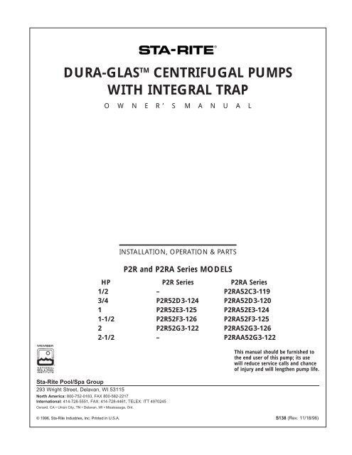
DURA-GLAS TM CENTRIFUGAL PUMPS<br />
WITH INTEGRAL TRAP<br />
O W N E R’ S<br />
M A N U A L<br />
INSTALLATION, OPERATION & PARTS<br />
P2R and P2RA Series MODELS<br />
HP P2R Series P2RA Series<br />
1/2 – P2RA52C3-119<br />
3/4 P2R52D3-124 P2RA52D3-120<br />
1 P2R52E3-125 P2RA52E3-124<br />
1-1/2 P2R52F3-126 P2RA52F3-125<br />
2 P2R52G3-122 P2RA52G3-126<br />
2-1/2 – P2RAA52G3-122<br />
Sta-Rite Pool/Spa Group<br />
293 Wright Street, Delavan, WI 53115<br />
North America: 800-752-0183, FAX 800-582-2217<br />
International: 414-728-5551, FAX: 414-728-4461, TELEX: ITT 4970245<br />
Oxnard, CA • Union City, TN • Delavan, WI • Mississauga, Ont.<br />
This manual should be furnished to<br />
the end user of this pump; its use<br />
will reduce service calls and chance<br />
of injury and will lengthen pump life.<br />
© 1996, Sta-Rite Industries, Inc. Printed in U.S.A. S138 (Rev. 11/18/96)
‘P2R’ and ‘P2RA’ SERIES PUMP<br />
WITH TRAP<br />
To avoid unneeded service calls, prevent possible injuries, and get the most<br />
out of your pump, READ THIS MANUAL CAREFULLY!<br />
The Sta-Rite ‘P2R’ and ‘P2RA’ Series Self-priming Centrifugal pump:<br />
• Is designed for use <strong>with</strong> swimming pools or as a <strong>centrifugal</strong> pump.<br />
• Is an excellent performer; <strong>dura</strong>ble, reliable.<br />
Table of Contents<br />
Safety Instructions ......................................................................................3<br />
Installation...............................................................................................4-5<br />
Electrical.....................................................................................................6<br />
Operation ...................................................................................................7<br />
Storage/Winterizing .................................................................................7-8<br />
Pump Service ........................................................................................9-10<br />
Troubleshooting Guide .............................................................................11<br />
Repair Parts List ........................................................................................12<br />
Warranty...................................................................................................15<br />
2
IMPORTANT<br />
SAFETY<br />
INSTRUCTIONS<br />
Always follow basic safety precautions<br />
<strong>with</strong> this equipment,<br />
including the following.<br />
To reduce the risk<br />
of injury, do not permit children<br />
to use this product unless they<br />
are closely supervised at all<br />
times.<br />
This pump is for use<br />
<strong>with</strong> permanently installed pools<br />
and may also be used <strong>with</strong> hot<br />
tubs and spas if so marked. Do<br />
not use <strong>with</strong> storable pools. A<br />
permanently installed pool is<br />
constructed in or on the ground<br />
or in a building such that it cannot<br />
be readily disassembled for<br />
storage. A storable pool is constructed<br />
so that it may be readily<br />
disassembled for storage and<br />
reassembled to its original<br />
integrity.<br />
SAVE THESE<br />
INSTRUCTIONS<br />
READ AND FOLLOW SAFETY<br />
INSTRUCTIONS!<br />
This is the safety alert symbol. When you see this symbol on your system<br />
or in this manual, look for one of the following signal words and<br />
be alert to the potential for personal injury.<br />
warns about hazards that will cause death, serious personal<br />
injury, or major property damage if ignored.<br />
warns about hazards that can cause death, serious personal<br />
injury, or major property damage if ignored.<br />
warns about hazards that will or can cause minor personal<br />
injury or property damage if ignored.<br />
NOTICE indicates special instructions not related to hazards.<br />
Carefully read and follow all safety instructions in this manual and on equipment.<br />
Keep safety labels in good condition; replace if missing or damaged.<br />
Incorrectly installed or tested equipment may fail, causing<br />
severe injury or property damage.<br />
Read and follow instructions in owner's manual when installing<br />
and operating equipment. Have a trained pool professional perform<br />
all pressure tests.<br />
1. Do not connect system to a high pressure or city water system.<br />
2. Use equipment only in a pool or spa installation.<br />
3. Trapped air in system can cause explosion. BE SURE all air is out of system<br />
before operating or testing equipment.<br />
Before pressure testing, make the following safety checks:<br />
Check all clamps, bolts, lids, and system accessories before testing.<br />
Release all air in system before testing.<br />
Tighten Sta-Rite <strong>trap</strong> lids to 30 ft. lbs. (4.1 kg-m) torque for testing.<br />
Water pressure for test must be less than 25 PSI (7.5 kg/cm 2 ).<br />
Water Temperature for test must be less than 100 o F. (38 o C).<br />
Limit test to 24 hours. After test, visually check system to be sure it is ready<br />
for operation. Remove <strong>trap</strong> lid and retighten hand tight only.<br />
NOTICE: These parameters apply to Sta-Rite equipment only. For<br />
non-Sta-Rite equipment, consult manufacturer.<br />
Motor normally operates at high temperature and will be too<br />
hot to touch. It is protected from heat damage during operation by an automatic<br />
internal cutoff switch. Before handling pump or motor, stop motor and<br />
allow it to cool for 20 minutes.<br />
3
FIGURE 1<br />
INSTALLATION<br />
Only qualified, licensed personnel should install pump and wiring.<br />
Pump mount must:<br />
Be solid - Level - Rigid - Vibration free. (To reduce vibration and pipe<br />
stress, bolt pump to mount.)<br />
Allow pump suction inlet height to be as close to water level as possible.<br />
Allow use of short, direct suction pipe (To reduce friction losses).<br />
Allow for gate valves in suction and discharge piping.<br />
Have adequate floor drainage to prevent flooding.<br />
Be protected from excess moisture.<br />
Allow adequate access for servicing pump and piping.<br />
NOTICE: Use Teflon tape or Plasto-Joint Stik 1 for making all threaded<br />
connections to the pump. Do not use pipe dope; pipe dope will cause<br />
stress cracking in the pump.<br />
NOTICE: Pump suction and discharge connections have molded in<br />
thread stops. DO NOT try to screw pipe in beyond these stops.<br />
Teflon Taping Instructions:<br />
Use only new or clean PVC pipe fittings.<br />
Wrap male pipe threads <strong>with</strong> one to two layers of Teflon tape. Cover<br />
entire threaded portion of pipe.<br />
Do not overtighten or tighten past thread stop in pump port!<br />
If leaks occur, remove pipe, clean off old tape, rewrap <strong>with</strong> one to two<br />
additional layers of tape and remake the connection.<br />
NOTICE: Support all piping connected <strong>with</strong> pump!<br />
1<br />
Lake Chemical Co., Chicago, Illinois<br />
4
Piping:<br />
Use at least 1-1/2" IPS PVC pipe <strong>with</strong> 5” <strong>trap</strong>. Use at least 2” pipe <strong>with</strong> 6”<br />
<strong>trap</strong>. Increase size if a long run is needed.<br />
To avoid strains on the pump, support both suction and discharge pipes<br />
independently. Place these supports near the pump.<br />
To avoid a strain left by a gap at the last connection, start all piping at the<br />
pump and run pipe away from the pump.<br />
Never use a suction pipe smaller than pump suction connection.<br />
To avoid airlocking, slope suction pipe slightly upward toward the pump.<br />
NOTICE: To prevent flooding when removing pump for service, all flooded<br />
suction systems must have gate valves in suction and discharge pipes.<br />
Fittings:<br />
Fittings restrict flow; for best efficiency use fewest possible fittings.<br />
Avoid fittings which could cause an air <strong>trap</strong>.<br />
Pool fittings must conform to International Association of Plumbing and<br />
Mechanical Officials (IAPMO) standards.<br />
Use only non-en<strong>trap</strong>ping suction fitting or double suction.<br />
TABLE I - RECOMMENDED FUSING AND WIRING DATA<br />
P2RA Series<br />
Motor Branch Fuse Max Load Voltage/ Dist. in Ft. (m) (Serv. to Motor)<br />
H.P. Rating Amps* Amps Hz/Phase 0-100’ (0-30) 101-200’ (31-60) 201-300’ (61-90)<br />
}<br />
1/2 15 2.4 200/60/3 14 (2) 14 (2) 14 (2)<br />
3/4 15 3.3 200/60/3 14 (2) 14 (2) 14 (2) Wire<br />
1 15 3.8 200/60/3 14 (2) 14 (2) 14 (2) Size<br />
1-1/2 15 5.6 200/60/3 14 (2) 14 (2) 14 (2) AWG<br />
2 15 6.2 200/60/3 14 (2) 14 (2) 14 (2) (mm)<br />
2-1/2 20 7.7 200/60/3 14 (2) 14 (2) 14 (2)<br />
*Time delay fuses are recommended instead of standard fuses in any motor circuit.<br />
P2R Series<br />
Motor Branch Fuse Max Load Voltage/ Dist. in Ft. (m) (Serv. to Motor)<br />
H.P. Rating Amps* Amps Hz/Phase 0-100’ (0-30) 101-200’ (31-60) 201-300’ (61-90)<br />
3/4 15 3.8 200/60/3 14 (2) 14 (2) 14 (2)<br />
}<br />
Wire<br />
1 15 5.6 200/60/3 14 (2) 14 (2) 14 (2) Size<br />
1-1/2 15 6.6 200/60/3 14 (2) 14 (2) 14 (2) AWG<br />
2 15 8.0 200/60/3 14 (2) 14 (2) 14 (2) (mm)<br />
*Time delay fuses are recommended instead of standard fuses in any motor circuit.<br />
5
Hazardous voltage.<br />
Can shock, burn,<br />
or cause death.<br />
Ground pump before<br />
connecting to<br />
power supply.<br />
GREEN<br />
GROUND<br />
SCREW<br />
BONDING<br />
LUG<br />
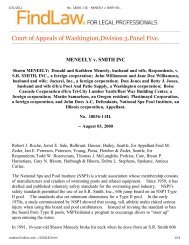
FIGURE 2: Typical ground screw<br />
and bonding lug locations<br />
ELECTRICAL<br />
Ground motor before connecting to electrical power supply. Failure<br />
to ground motor can cause severe or fatal electrical shock<br />
hazard.<br />
Do not ground to a gas supply line.<br />
To avoid dangerous or fatal electrical shock, turn OFF power to<br />
motor before working on electrical connections.<br />
Ground Fault Circuit Interrupter (GFCI) tripping indicates an electrical<br />
problem. If GFCI trips and will not reset, have a qualified<br />
electrician inspect and repair electrical system.<br />
Exactly match supply voltage to nameplate voltage! Incorrect voltage<br />
can cause fire or seriously damage motor and voids warranty.<br />
If in doubt consult a licensed electrician.<br />
Voltage:<br />
Voltage at motor must be not more than 10% above or below motor nameplate<br />
rated voltage or motor may overheat, causing overload tripping and<br />
reduced component life. If voltage is less than 90% or more than 110% of<br />
rated voltage when motor is running at full load, consult power company.<br />
Grounding/Bonding:<br />
Install, ground, bond and wire motor according to local or National<br />
Electrical Code requirements.<br />
Permanently ground motor. Use green ground terminal provided under<br />
motor canopy or access plate (See Figure 2); use size and type wire required<br />
by code. Connect motor ground terminal to electrical service ground.<br />
Bond motor to pool structure. Use a solid copper conductor, size No. 8<br />
AWG or larger. Run wire from external bonding lug (see Figure 2) to reinforcing<br />
rod or mesh.<br />
Wiring:<br />
Pump must be permanently connected to circuit. Table I, Page 5, gives correct<br />
wire and circuit breaker sizes for the pump alone. If other lights or<br />
appliances are also on the same circuit, be sure to add their amp loads to<br />
pump amp load before figuring wire and circuit breaker sizes. (If unsure how<br />
to do this or if this is confusing, consult a licensed electrician.) Use the load<br />
circuit breaker as the master on-off switch.<br />
Install a Ground Fault Circuit Interrupter (GFCI) in circuit; it will sense a<br />
short-circuit to ground and disconnect power before it becomes dangerous<br />
to pool users. For size of GFCI required and test procedures for GFCI, see<br />
manufacturer’s instruction.<br />
In case of power outage, check GFCI for tripping (which will prevent normal<br />
pump operation). Reset if necessary.<br />
NOTICE: If you do not use conduit when wiring motor, be sure to seal wire<br />
opening on end of motor to prevent dirt, bugs, etc., from entering.<br />
6
Hazardous suction.<br />
Can <strong>trap</strong> hair or<br />
body parts, causing<br />
severe injury<br />
or death.<br />
Do not block<br />
suction.<br />
OPERATION<br />
NEVER run pump dry! Running pump dry may damage seals, causing<br />
leakage and flooding! Fill pump <strong>with</strong> water before starting<br />
motor.<br />
Before removing <strong>trap</strong> cover:<br />
1. STOP PUMP before proceeding.<br />
2. CLOSE GATE VALVES in suction and discharge pipes.<br />
3. RELEASE ALL PRESSURE from pump and piping system.<br />
4. NEVER tighten or loosen clamp while pump is operating!<br />
If pump is being pressure tested, be sure pressure has been released<br />
before removing <strong>trap</strong> cover!<br />
Do not block pump suction! To do so <strong>with</strong> body may cause severe or<br />
fatal injury. Small children using pool must ALWAYS have close adult<br />
supervision!<br />
Priming Pump:<br />
Release all air from filter and piping system: see filter owner’s manual.<br />
In a flooded suction system (water source higher than pump), pump will<br />
prime itself when suction and discharge valves are opened.<br />
If pump is not in a flooded suction system, unscrew and remove <strong>trap</strong> cover;<br />
fill <strong>trap</strong> and pump <strong>with</strong> water.<br />
NOTICE: Lubricate <strong>trap</strong> cover O-Ring <strong>with</strong> petroleum jelly each time it is<br />
removed.<br />
Clean and inspect O-Ring; reinstall on <strong>trap</strong> cover.<br />
Replace <strong>trap</strong> cover on <strong>trap</strong>; turn clockwise to tighten cover.<br />
NOTICE: Tighten <strong>trap</strong> cover by hand only (no wrenches)! Use a wrench<br />
only if necessary to remove lid!<br />
Pump should prime now. Priming time will depend on vertical length of suction<br />
lift and horizontal length of suction piping.<br />
If pump does not prime, make sure that all valves are open, suction pipe end<br />
is under water, and that there are no leaks in suction pipe. See<br />
Troubleshooting Guide, Page 10.<br />
Storage/Winterizing:<br />
Explosion hazard. Purging the system <strong>with</strong> compressed air can<br />
cause components to explode, <strong>with</strong> risk of severe injury or death to anyone<br />
nearby. Use only a low pressure (below 5 PSI), high volume blower when<br />
purging the pump, filter, or piping.<br />
NOTICE: Allowing pump to freeze will damage pump and void warranty!<br />
NOTICE: Do not use anti-freeze solutions (except propylene glycol) in your<br />
pool/spa system. Propylene glycol is non-toxic and will not damage plastic<br />
system components; other anti-freezes are highly toxic and may damage<br />
plastic components in the system.<br />
Drain all water from pump and piping when expecting freezing temperatures<br />
or when storing pump for a long time (see instructions, Page 8).<br />
Keep motor dry and covered during storage.<br />
To avoid condensation/corrosion problems, do not cover pump <strong>with</strong> plastic.<br />
For outdoor/unprotected installations:<br />
1. Enclose entire system in a weatherproof enclosure.<br />
2. To avoid condensation/corrosion damage, allow ventilation; do not<br />
wrap system in plastic.<br />
3. Use a 40% propylene glycol/60% water solution to protect pump to -<br />
50°F.<br />
7
Hazardous voltage.<br />
Can shock, burn,<br />
or cause death.<br />
Disconnect power<br />
before working<br />
on pump or motor.<br />
Draining Pump:<br />
1. Pump down water level below all inlets to the pool.<br />
To avoid dangerous or fatal electrical shock hazard, turn OFF power<br />
to motor before draining pump.<br />
2. Gravity drain system as far as possible.<br />
3. Remove <strong>trap</strong> cover and use low pressure (5 PSI or less) air to blow accumulated<br />
water from the piping system. Use a Sta-Rite U79-11 Lid Wrench<br />
to remove <strong>trap</strong> covers that have been overtightened or have taken a set<br />
and cannot be removed by hand.<br />
4. Protect areas which retain water <strong>with</strong> non-toxic propylene glycol<br />
antifreeze (“RV antifreeze”).<br />
5. Cap inlet piping after draining to keep water out of the pipes.<br />
6. To prevent pump from freezing, remove <strong>trap</strong> cover and drain the tank<br />
body through the drain plug (Key No. 18, Page 11). Clean pump thoroughly;<br />
replace <strong>trap</strong> cover.<br />
NOTICE: Tighten <strong>trap</strong> cover by hand only (no wrenches)! Use a wrench<br />
only if necessary to remove cover!<br />
7. Be sure motor is kept dry and covered.<br />
Startup For Winterized Equipment:<br />
1. Remove any temporary weather protection placed around system for shutdown.<br />
2. Follow filter manufacturer’s instructions for reactivation of the filter.<br />
3. Inspect all electrical wiring for damage or deterioration over the shutdown<br />
period. Have a qualified serviceman repair wiring as needed.<br />
4. Inspect and tighten all watertight connections.<br />
5. Open all valves in suction and return piping.<br />
6. Remove any winterizing plugs in piping system.<br />
7. Drain all antifreeze from system.<br />
8. Close all drain valves and replace all drain plugs in piping system.<br />
9. Prime pump according to instructions on Page 7.<br />
PUMP SERVICE<br />
Pump should only be serviced by qualified personnel.<br />
Be sure to prime pump (Page 7) before starting.<br />
Before removing <strong>trap</strong> cover:<br />
1. STOP PUMP before proceeding.<br />
2. CLOSE GATE VALVES in suction and discharge pipes.<br />
3. RELEASE ALL PRESSURE from pump and piping system.<br />
4. NEVER tighten or loosen clamp while pump is operating!<br />
To avoid dangerous or fatal electrical shock hazard, turn OFF power<br />
to motor before working on pump or motor.<br />
Aside from lubricating <strong>trap</strong> cover O-Ring, no lubrication or regular maintenance<br />
is needed beyond reasonable care and periodic cleaning.<br />
If shaft seal is worn or damaged, repair as follows:<br />
Pump Disassembly/Removing Old Seal:<br />
FIGURE 3<br />
Disconnect power to pump motor.<br />
Be sure gate valves on suction and return piping are closed before starting<br />
work.<br />
Release all pressure by opening all vents before starting work.<br />
1. Drain pump by removing drain plugs on bottom of pump body and <strong>trap</strong><br />
body.<br />
8
FIGURE 4<br />
FIGURE 5<br />
WIPE ON SMALL AMOUNT OF<br />
NON-HARDENING PERMATEX<br />
ON THIS SURFACE<br />
FIGURE 6<br />
FIGURE 7<br />
FIGURE 8<br />
1-3/8" O.D.<br />
WASHER<br />
REMOVE<br />
SURPLUS<br />
PERMATEX<br />
PROPERLY<br />
SEATED<br />
7/8" SOCKET<br />
BOLT<br />
038 0893<br />
039 0893<br />
2. Be sure there is no pressure in <strong>trap</strong> body; remove cover (unscrew by turning<br />
counterclockwise).<br />
3. Remove clamp holding pump halves together.<br />
4. Remove pump base mounting bolts, if used. Motor and seal plate assembly<br />
can now be pulled away from pump body.<br />
5. Remove five screws and washers holding diffuser to seal plate. Remove<br />
diffuser.<br />
6. Remove motor canopy. Being careful not to touch capacitor terminals,<br />
loosen capacitor clamp and move capacitor to one side.<br />
7. Hold shaft <strong>with</strong> 7/16” open-end wrench on motor shaft flats.<br />
8. Unscrew impeller from shaft (turn counterclockwise when facing it).<br />
9. Remove four screws holding seal plate to motor.<br />
10. Place seal plate face down on flat surface and tap out ceramic seat<br />
(Figure 4).<br />
NOTICE: Do not force out heat sink insert (Key No, 7, Page 11). If insert<br />
has moved, pump will leak; see “Installing Insert”, below.)<br />
11. Clean seal cavity in seal plate and clean motor shaft.<br />
Pump Reassembly/Installing New Seal:<br />
1. Ceramic seat must be clean and free of dirt, grease, dust, etc. Wet outer<br />
edge of O-Ring <strong>with</strong> small amount of liquid detergent; press ceramic<br />
seat into seal plate cavity firmly and squarely <strong>with</strong> finger pressure<br />
(Figure 5).<br />
2. If ceramic seat will not locate properly, remove it, place face up on<br />
bench and reclean cavity. Ceramic seat should now locate.<br />
3. If seat still will not locate properly, place a cardboard washer over the<br />
polished face and use a piece of 3/4" standard pipe for pressing purposes.<br />
NOTICE: Be sure not to scratch or mar polished surface or seal will<br />
leak.<br />
4. Remount seal plate to motor. Tighten bolts to 60-80 inch-lbs.<br />
(69-92 cm/kg) torque.<br />
5. Apply a small amount of liquid detergent to inside diameter of rotating<br />
half of seal.<br />
6. Slide rotating seal member, polished face first, over threaded shaft end<br />
and shaft shoulder until rubber drive ring hits shaft shoulder. (Figure 3).<br />
NOTICE: Be sure not to nick or scratch polished seal face; seal will leak<br />
if face is damaged.<br />
7. Screw impeller onto shaft (clockwise); this will automatically locate seal<br />
in seal plate.<br />
8. Mount diffuser on seal plate; tighten screws to 10-14 inch-lbs.<br />
(11.5-16 cm/kg) torque.<br />
9. Assemble motor and seal plate to volute; be sure clamp is properly seated.<br />
NOTICE: Clamp knob can be located in any position around volute;<br />
if it is moved after assembly, tighten knob while tapping around clamp<br />
to assist sealing. Do not move clamp while pump is full of water.<br />
10. Reinstall pump base mounting bolts (if used) and prime pump according<br />
to instructions on Page 7.<br />
Installing Heat Sink Insert:<br />
If the heat sink insert moves or shifts during seal removal, remove and<br />
reinstall it to prevent leakage.<br />
1. To remove heat sink insert, grasp <strong>with</strong> fingers at the large end and move<br />
back and forth. Do not deform.<br />
2. Replace heat sink insert as follows:<br />
A. Clean off old sealant and foreign material; clean out insert cavity.<br />
B. Apply a small amount of non-hardening silicone RTV on surface of<br />
insert (see Figure 6).<br />
C. Pull insert into cavity (see Figure 7).<br />
D. Remove surplus silicone RTV from insert cavity (see Figure 8).<br />
9
TROUBLESHOOTING GUIDE<br />
Read and understand safety and operating instructions in this manual<br />
before doing any work on pump!<br />
Only qualified personnel should electrically test pump motor!<br />
FAILURE TO PUMP; REDUCED CAPACITY OR DISCHARGE PRESSURE<br />
Hazardous voltage.<br />
Can shock, burn,<br />
or cause death.<br />
Disconnect power<br />
before working<br />
on pump or motor.<br />
Suction leaks/lost prime:<br />
1. Pump must be primed; make sure that pump volute and <strong>trap</strong> are full of<br />
water. See priming instructions, Page 7.<br />
2. Make sure there are no leaks in suction piping.<br />
3. Make sure suction pipe inlet is well below the water level to prevent<br />
pump from sucking air.<br />
4. If suction <strong>trap</strong> gasket is defective, replace it.<br />
5. Suction lift of 15 to 25 feet will reduce performance. Suction lift of more<br />
than 25 feet will prevent pumping and cause pump to lose prime. In<br />
either case, move pump closer (vertically) to water source. Make sure<br />
suction pipe is large enough.<br />
Clogged pipe/<strong>trap</strong>/impeller, worn impeller:<br />
6. Make sure suction <strong>trap</strong> is not clogged; if it is, clean <strong>trap</strong> and strainer.<br />
7. Make sure impeller is not clogged (follow steps 1 through 7 under<br />
“Removing Old Seal”, Page 8; check impeller for clogging; follow steps<br />
7 through 11 under “Installing New Seal”, Page 9, for reassembly).<br />
8. Impeller and diffuser may be worn. If so, order replacement parts from<br />
Repair Parts List, Page 11.<br />
9. Pump may be trying to push too high a column of water. If so, a “higher<br />
head” pump is needed.<br />
Electrical:<br />
10. Pump may be running too slowly; check voltage at motor terminals and<br />
at meter while pump is running. If low, see wiring instructions or consult<br />
power company. Check for loose connections.<br />
11. Pump may be too hot.<br />
A. Check line voltage; if less than 90% or more than 110% of rated<br />
voltage consult a licensed electrician.<br />
B. Increase ventilation.<br />
C. Reduce ambient temperature.<br />
D. Tighten any loose connections.<br />
Mechanical Troubles and Noise:<br />
1. If suction and discharge piping are not adequately supported, pump<br />
assembly will be strained. See “Installation”, Page 4.<br />
2. Do not mount pump on a wooden platform! Securely mount on concrete<br />
platform for quietest performance.<br />
10
1<br />
2 3<br />
4<br />
5<br />
6<br />
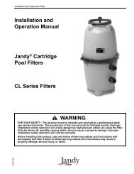
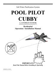
REPAIR PARTS LIST<br />
P2R SERIES<br />
DURA-GLAS ® POOL PUMP<br />
3/4 through 2 H.P. Models<br />
21<br />
7<br />
8<br />
10<br />
9<br />
18<br />
20<br />
19<br />
11<br />
14<br />
15<br />
17<br />
Key Part Part<br />
No. Description Qty. No.<br />
1 Motor 1 Chart at Right<br />
2 Screw #10-32 x 1/2” 1 U30-856ZP<br />
3 Bonding Lug 1 U17-568<br />
4 Water Slinger 1 C69-2<br />
5 Seal Plate 1 C203-137P1<br />
6 O-Ring 1 U9-228A<br />
7 Insert 1 J3-2<br />
8 Shaft Seal 1 U109-93SS<br />
9 Clamp 1 C19-37A<br />
• Clamp Knob 1 WC36-22<br />
10 Impeller 1 Chart at Right<br />
• Impeller Screw 1 C30-12<br />
11 Diffuser 1 C1-200PA<br />
12 Screw #8-32 x 7/8” 5 U30-542SS<br />
13 Washer, #8 Lock 5 U43-21SS<br />
14 Diffuser O-Ring 1 U9-226<br />
15 Pump Body 1 C176-47P1<br />
16 Drain Plug 1/4” NPT 1 U178-920P<br />
17 Base w/Motor Pad 1 C104-42P<br />
18 Motor Pad 1 C35-11<br />
19 Washer, Flat 2 U43-42SS<br />
20 Screw 3/8-16 x 1-3/4” Hex Head 2 U30-77SS<br />
21 Screw 3/8-16 x 1” Hex Head 2 U30-74SS<br />
• Reducer 2” x 1-1/2” 1 C78-7P<br />
• Tag, “CAUTION This pump equipped 61002-0002<br />
<strong>with</strong> mechanical shaft seal. . .”<br />
• Decal, “Overtight. . .” U27-644<br />
• Tag, “IMPORTANT/WARNING/ C63-12<br />
CAUTION. . .”<br />
• Tag, “CAUTION. . .” C63-11<br />
• Model Plate U33-104B<br />
13<br />
12<br />
1831 0695<br />
Parts are common to all models listed except as noted:<br />
Key Nos. 1, Motor; and 10, Impeller are listed below.<br />
Motor No. Impeller No.<br />
Model No. HP Key No. 1 Key No. 10<br />
200 Volt<br />
P2R52D3-124 3/4 AP100DH2 C105-138PEBA<br />
P2R52E3-125 1 AP100EH2 C105-137PEBA<br />
P2R52F3-126 1-1/2 AP100FH2 C105-137PDBA<br />
P2R52G3-122 2 AP100GH2 C105-137PDA<br />
P2R5 models include 5” <strong>trap</strong>, Pkg. 115.<br />
P2RX models do not include <strong>trap</strong>.<br />
For <strong>trap</strong> parts, see Page 13.<br />
For Parts-Pak parts, see Page 13.<br />
16<br />
• Not illustrated.<br />
11
1<br />
21<br />
2 3<br />
4<br />
5<br />
6<br />
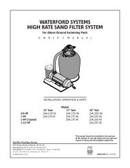
REPAIR PARTS LIST<br />
P2RA SERIES<br />
DURA-GLAS ® POOL PUMP<br />
1/2 through 2-1/2 H.P. Models<br />
7<br />
8<br />
10<br />
9<br />
18<br />
20<br />
19<br />
11<br />
14<br />
15<br />
17<br />
Key Part Part<br />
No. Description Qty. No.<br />
1 Motor 1 Chart at Right<br />
2 Screw #10-32 x 1/2” 1 U30-856ZP<br />
3 Bonding Lug 1 U17-568<br />
4 Water Slinger 1 C69-2<br />
5 Seal Plate* 1 C203-137P1<br />
6 O-Ring 1 U9-228A<br />
7 Insert 1 J3-2<br />
8 Shaft Seal 1 U109-93SS<br />
9 Clamp 1 C19-37A<br />
• Clamp Knob 1 WC36-22<br />
10 Impeller 1 Chart at Right<br />
• Impeller Screw 1 C30-12<br />
11 Diffuser** 1 C1-200PA<br />
12 Screw #8-32 x 7/8” 5 U30-542SS<br />
13 Washer, #8 Lock 5 U43-21SS<br />
14 Diffuser O-Ring 1 U9-226<br />
15 Pump Body 1 C176-47P1<br />
16 Drain Plug 1/4” NPT 1 U178-920P<br />
17 Base w/Motor Pad 1 C104-42P<br />
18 Motor Pad 1 C35-11<br />
19 Washer, Flat 2 U43-42SS<br />
20 Screw 3/8-16 x 1-3/4” Hex Head 2 U30-77SS<br />
21 Screw 3/8-16 x 1” Hex Head 2 U30-74SS<br />
• Reducer 2” x 1-1/2” 1 C78-7P<br />
• Tag, “CAUTION This pump equipped 61002-0002<br />
<strong>with</strong> mechanical shaft seal. . .”<br />
• Decal, “Overtight. . .” U27-644<br />
• Tag, “IMPORTANT/WARNING/ C63-12<br />
CAUTION. . .”<br />
• Tag, “CAUTION. . .” C63-11<br />
• Model Plate U33-104B<br />
13<br />
12<br />
1831 0695<br />
Parts are common to all models listed except as noted:<br />
Key Nos. 1, Motor; and 10, Impeller are listed below.<br />
Motor No. Impeller No.<br />
Model No. HP Key No. 1 Key No. 10<br />
200 Volt<br />
P2RA52C3-119 1/2 AP100CH2 C105-92PRA<br />
P2RA52D3-120 3/4 AP100DL2 C105-92PSA<br />
P2RA52E3-124 1 AP100EL2 C105-138PEBA<br />
P2RA52F3-125 1-1/2 AP100FL2 C105-137PDBA<br />
P2RA52G3-126 2 AP100GL2 C105-137PDBA<br />
P2RAA52G3-122 2-1/2 AP100G5L2 C105-137PDA<br />
P2R5 models include 5” <strong>trap</strong>, Pkg. 115.<br />
P2RX models do not include <strong>trap</strong>.<br />
For <strong>trap</strong> parts, see Page 13.<br />
For Parts-Pak parts, see Page 13.<br />
16<br />
* Model P2RAA52G3-122 uses Part No. C203-137P.<br />
** Model P2RA52C3 uses Part No. C1-217P; P2RA52D3 uses Part No. C1-216P.<br />
• Not illustrated.<br />
12
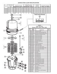
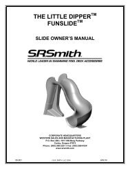
5” TRAP/ADAPTER ASSEMBLY PKG. 115<br />
REPAIR PARTS LIST - 5” and 6” TRAPS*<br />
1<br />
2<br />
3<br />
4<br />
Part No.<br />
Key Part Pkg. 115 Pkg. 161<br />
No. Description 5” Trap 6” Trap<br />
1 Trap Cover C3-139P1 16920-0011<br />
2 O-Ring - Cover U9-229 16920-0012<br />
3 Strainer Basket C108-33P 16920-0017<br />
4 Trap Body C153-53P1 C153-58P<br />
5 Gasket C20-123 C20-123<br />
6 Pipe Plug - 1/4” NPT U178-920P U178-920P<br />
(w/O-Ring)<br />
7 Capscrew-5/16-18x1-1/4” U30-64SS(4) U30-64SS(4)<br />
8 Washer, Lock 5/16” U43-11SS(4) U43-11SS(4)<br />
9 Washer, Flat 5/16” U43-41SS(4) U43-41SS(4)<br />
*Quantity one unless otherwise indicated ( ).<br />
5<br />
Overhaul Kits<br />
9<br />
8<br />
7<br />
1844 0695<br />
6<br />
Parts-Pak Number<br />
H.P. P2R P2RA<br />
1/2 PP1011 PP1010<br />
3/4 PP1014 PP1011<br />
1 PP1016 PP1014<br />
1-1/2 PP1018 PP1016<br />
2 – PP1018<br />
6” TRAP/ADAPTER ASSEMBLY PKG. 161<br />
1<br />
2<br />
3<br />
4<br />
Kit includes: Impeller, Diffuser, Shaft Seal,<br />
Gaskets, O-Rings, Hardware, Shims, Wear Rings<br />
and Inserts.<br />
Seal/Gasket Kit<br />
Kit includes Shaft Seal, Gaskets, and O-Rings.<br />
For all horsepower P2R and P2RA series <strong>pumps</strong>.<br />
Parts-Pak No. PP1000.<br />
Trap Cover/O-Ring Kit (5” <strong>trap</strong>)<br />
Kit includes C3-139P1Trap Cover and U9-229<br />
O-Ring. For all horsepower P2R and P2RA series<br />
<strong>pumps</strong>. Parts-Pak No. PP2075.<br />
Trap Basket/O-Ring Kit (5” <strong>trap</strong>)<br />
Kit includes C108-33P Strainer Basket and U9-<br />
229 O-Ring. For all horsepower P2R and P2RA<br />
series <strong>pumps</strong>. Parts-Pak No. PP2062.<br />
5<br />
9<br />
8<br />
7<br />
1843 0695<br />
6<br />
13
Pumps, filters, skimmers, underwater lights (except bulbs),<br />
accessories and fittings manufactured by Sta-Rite are warranted<br />
to be free of defects in material and workmanship<br />
for one (1) year from date of installation.<br />
Product specific warranties:<br />
Year from date<br />
of installation<br />
HRPB, DEPB and System 3 – Tanks . . . . . . . . . .10 years<br />
Internal filter components and valves . . . . . . . 1 year<br />
Automatic Pool Cleaners including Hose . . . . . . 2 years<br />
Cristal-Flo filters – Tanks . . . . . . . . . .10 years pro-rated*<br />
Valve and internal components. . . . . . . . . . . . . 1 year<br />
Posi-Flo II – Tanks . . . . . . . . . . . . . . . . . . . . . . . .10 years<br />
Elements . . . . . . . . . . . . . . . . . . . . . . . . . . . . . 1 year<br />
Waterford Sand – Tanks . . . . . . . . . . .10 years pro-rated*<br />
Pumps . . . . . . . . . . . . . . . . . . . . . . . . . . . . . . . 1 year<br />
Valve and Internals . . . . . . . . . . . . . . . . . . . . . . 1 year<br />
Waterford Cartridge – Filter Tank . . . . . . . . . . . .10 years<br />
Pumps . . . . . . . . . . . . . . . . . . . . . . . . . . . . . . . 1 year<br />
System 3 Above Ground Systems – Tanks . . . . . .10 years<br />
Pumps . . . . . . . . . . . . . . . . . . . . . . . . . . . . . . . 1 year<br />
Platform and Internals . . . . . . . . . . . . . . . . . . . 1 year<br />
Pumps . . . . . . . . . . . . . . . . . . . . . . . . . . . . . . . . . . 1 year<br />
When equipped <strong>with</strong> A.O. Smith<br />
2-compartment motors (Does not include<br />
<strong>pumps</strong> sold as part of a systems package) . . . . 2 years<br />
STA-RITE LIMITED WARRANTY<br />
The foregoing warranties relate to the original consumer<br />
purchaser (“Purchaser”) only. Sta-Rite shall have the option<br />
to repair or replace the defective product, at its sole discretion.<br />
Purchasers must pay all labor and shipping charges<br />
necessary to replace the product covered by this warranty.<br />
Requests for warranty service must be made through the<br />
installing dealer. This warranty shall not apply to any product<br />
that has been subject to negligence, misapplication,<br />
improper installation or maintenance, or other circumstances<br />
which are not in Sta-Rite’s direct control.<br />
* Full warranty coverage is in effect for one year after installation.<br />
The pro-rated warranty covers the tank only during<br />
the 2nd through 10th year after installation. The amount<br />
covered decreases by 10% each year. (ie., 2nd year 90%<br />
covered, 3rd year 80% covered, etc.).<br />
This warranty sets forth Sta-Rite’s sole obligation and<br />
Purchaser’s exclusive remedy for defective products.<br />
STA-RITE SHALL NOT BE LIABLE FOR ANY CONSEQUEN-<br />
TIAL, INCIDENTAL OR CONTINGENT DAMAGES WHAT-<br />
SOEVER.<br />
THE FOREGOING WARRANTIES ARE EXCLUSIVE AND IN<br />
LIEU OF ALL OTHER EXPRESS WARRANTIES. IMPLIED<br />
WARRANTIES, INCLUDING BUT NOT LIMITED TO THE<br />
IMPLIED WARRANTIES OF MERCHANTABILITY AND FIT-<br />
NESS FOR A PARTICULAR PURPOSE, SHALL NOT EXTEND<br />
BEYOND THE DURATION OF THE APPLICABLE EXPRESS<br />
WARRANTIES PROVIDED HEREIN.<br />
Some states do not allow the exclusion or limitation of incidental<br />
or consequential damages or limitations on how<br />
long an implied warranty lasts, so the above limitations or<br />
exclusion may not apply to you. This warranty gives you<br />
specific legal rights and you may also have other rights<br />
which vary from state to state.<br />
Supersedes all previous publications.<br />
Sta-Rite Industries, Inc.<br />
293 Wright Street<br />
Delavan, WI 53115<br />
▲ Retain Warranty Certificate (upper portion) in a safe and convenient location for your records.<br />
DETACH HERE: Fill out bottom portion completely and mail <strong>with</strong>in 10 days of purchase/installation to:<br />
▼ Sta-Rite, Attn: Warranty Dept., 293 Wright St., Delavan, WI 53115<br />
Warranty Registration Card<br />
Name<br />
Address<br />
City State Zip<br />
Purchase Date<br />
Years pool has been in service ■ less than 1 ■ 1-3 ■ 3-5 ■ 5-10<br />
Purchased from:<br />
Company name<br />
Address<br />
City State Zip<br />
Product Purchased<br />
■ New installation<br />
■ Replacement<br />
Please send me more information on these<br />
other products from Sta-Rite.<br />
Type of Pool ■ Inground ■ Vinyl ■ Fiberglass ■ Gunite<br />
Size of Pool<br />
■ Pumps ■ Filters ■ Automatic Pool Cleaners<br />
■ Maintenance Equipment ■ Test Strips<br />
S4877PS (7/10/97)