AMPTIAC Quarterly, Vol. 9, No. 2, Summer/Fall 2005 - Advanced ...
AMPTIAC Quarterly, Vol. 9, No. 2, Summer/Fall 2005 - Advanced ...
AMPTIAC Quarterly, Vol. 9, No. 2, Summer/Fall 2005 - Advanced ...

Create successful ePaper yourself
Turn your PDF publications into a flip-book with our unique Google optimized e-Paper software.
Materials-related issues are rarely mentioned in the mainstream<br />
news, but with the recent controversy surrounding bullet-proof<br />
vests there has been significant interest from the media. Bulletproof<br />
vests are quite literally a vital component of the uniform<br />
for many of the men and women serving our country, either in<br />
law enforcement or in the military, and have been directly<br />
attributed with saving thousands of lives.<br />
Editorial:<br />
Protecting Those<br />
Who Protect Us<br />
The issue that has caught the attention<br />
of the media is that certain types of vests<br />
might fail when they are needed to protect,<br />
and law enforcement officers may<br />
unknowingly be at risk. The vests in question<br />
are made of a Zylon ® -based fabric, which has been shown<br />
to degrade under high temperature and high humidity conditions,<br />
and are currently being used by many law enforcement<br />
agencies. The manufacturer of the fiber and the maker of the<br />
bullet-proof vests have been involved in a small media war over<br />
who’s at fault for the potentially unreliable vests.<br />
In response to concerns over bullet-proof vests made from<br />
Zylon, the National Institute of Justice (NIJ), which is the<br />
research, development and evaluation agency of the<br />
Department of Justice, has led an effort to evaluate the reliability<br />
of this fiber and the vests made from it. The NIJ has released<br />
an interim status report updating the progress of the evaluation<br />
and a supplemental report detailing the possible causes of body<br />
armor failure in an incident where a Pennsylvania police officer<br />
was shot and seriously injured. The supplemental report offers<br />
several theories but did not reach any specific conclusions on<br />
why the bullet completely penetrated the officer’s vest.<br />
However, this report and the interim status report also suggest<br />
that Zylon is vulnerable to degradation and must be protected<br />
from its susceptibilities to provide long-term durability.<br />
Meanwhile, the US Military has been pursuing development of<br />
the Zylon fiber and its application to body armor, because it<br />
can potentially reduce the weight of current body armor by<br />
25%. The study by the NIJ, therefore, is very important in<br />
light of the recent controversy and interest from the military.<br />
The military has been supplying its troops with upgraded<br />
body armor vests to replace the old Personnel Armor System<br />
for Ground Troops (PASGT) vests, but there has been some<br />
concern over the reliability of a group of these new vests as<br />
well. The new Interceptor ® vests, which are made from an<br />
improved Kevlar ® fiber, feature superior ballistic performance<br />
and are substantially lighter compared to the old<br />
PASGT body armor. Though there have been claims that the<br />
new vests failed to meet the standard<br />
requirements, they still are the best available<br />
lightweight armor for ground troops<br />
and offer better protection than the old<br />
vests. The new bullet-proof vests are being<br />
worn by soldiers in Iraq and Afghanistan,<br />
and together with their composite helmets have been credited<br />
with saving many soldiers’ lives.<br />
While the media certainly benefits from reporting on these<br />
sorts of controversies, it also creates some awareness for<br />
materials-related issues and promotes the need for further<br />
development and advancement of materials to a broader<br />
audience. Reliability of body armor is an extremely important<br />
issue, as our military and law enforcement organizations have<br />
become dependent on these vests for protecting their most<br />
important assets. Further critical evaluation of existing lightweight<br />
armor technologies and the development of new<br />
materials for armor applications can only lead to better,<br />
lighter armor, which will help improve our soldiers’ ability to<br />
maneuver and survive, and ultimately will keep our military<br />
the best equipped in the world.<br />
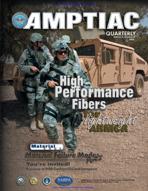
This issue of the <strong>AMPTIAC</strong> <strong>Quarterly</strong> features an article on<br />
high performance fibers for flexible and rigid lightweight<br />
armor applications. Because of the vital importance of body<br />
armor and bullet-proof vests and the recent media attention<br />
surrounding them, we wanted to publish an article that focuses<br />
on the fundamental materials that enable these armors. The<br />
article highlights current fiber technologies as well as fibers<br />
for future systems, and provides a closer look at what is protecting<br />
the officers and soldiers who are on the battlefield<br />
protecting our way of life.<br />
Ben Craig<br />
Editor-In-Chief, <strong>AMPTIAC</strong><br />
Editor-in-Chief<br />
Benjamin D. Craig<br />
Publication Design<br />
Cynthia Long<br />
Tamara R. Grossman<br />
Information Processing<br />
Judy E. Tallarino<br />
Patricia Bissonette<br />
Inquiry Services<br />
David J. Brumbaugh<br />
Product Sales<br />
Gina Nash<br />
The <strong>AMPTIAC</strong> <strong>Quarterly</strong> is published by the <strong>Advanced</strong> Materials and Processes Technology Information Analysis<br />
Center (<strong>AMPTIAC</strong>). <strong>AMPTIAC</strong> is a DOD-sponsored Information Analysis Center, administratively managed by<br />
the Defense Technical Information Center (DTIC). Policy oversight is provided by the Office of the Secretary of<br />
Defense, Director of Defense Research and Engineering (DDR&E). The <strong>AMPTIAC</strong> <strong>Quarterly</strong> is distributed to<br />
more than 15,000 materials professionals around the world.<br />
Inquiries about <strong>AMPTIAC</strong> capabilities, products, and services may be addressed to<br />
David H. Rose<br />
Director, <strong>AMPTIAC</strong><br />
315-339-7023<br />
EMAIL: amptiac@alionscience.com<br />
URL: http://amptiac.alionscience.com<br />
We welcome your input! To submit your related articles, photos, notices, or ideas for future issues, please contact:<br />
<strong>AMPTIAC</strong><br />
ATTN: BENJAMIN D. CRAIG<br />
201 Mill Street<br />
Rome, New York 13440<br />
PHONE: 315.339.7019<br />
FAX: 315.339.7107<br />
EMAIL:<br />
amptiac_news@alionscience.com
Richard A. Lane<br />
<strong>AMPTIAC</strong><br />
Rome, NY<br />
INTRODUCTION<br />
Military systems, especially those supporting ground forces, are<br />
being transformed to become faster, more agile, and more<br />
mobile, as the US faces opponents who use guerilla-warfare tactics<br />
and where systems must be quickly moved to operations<br />
located throughout the world. As a result, an increased demand<br />
for improved lightweight body armor and lightweight vehicle<br />
armor has led to the development of new armor materials.<br />
High performance fiber materials have been exploited for both<br />
applications. For example, they can be used as soft, flexible<br />
fiber mats for body armor or as reinforcements in rigid polymer<br />
matrix composites (PMCs) for lightweight vehicle armor.<br />
Throughout history, lightweight and flexible materials have<br />
been sought to reduce the weight of body armor systems to<br />
enhance mobility, while providing protection against specified<br />
threats. Early materials included leather and even silk, which<br />
were used in conjunction with metal plates to provide the<br />
needed protection. The elimination of metals altogether in<br />
body armor systems however, did not take place until the<br />
Korean War.[1] At that time, a nylon fabric vest and an E-glass<br />
fiber/ethyl cellulose composite vest, which had been developed<br />
during the course of World War II, were put into service.<br />
These vests provided protection against bomb and grenade<br />
fragments, which accounted for the high majority of injuries<br />
and deaths among soldiers. Although nylon and E-glass fibers<br />
continue to find some use today due to their low cost, high<br />
performance fibers are now the standard for most fiberreinforced<br />
armor applications. High performance fibers are<br />
typically used in the form of woven fabrics for vests and<br />
either woven or non-woven reinforcements within PMCs<br />
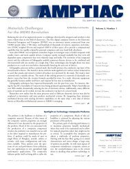
for helmets. Figure 1 shows the Interceptor ®* vest and composite<br />
helmet currently worn by US military troops. Ceramic<br />
insert plates may be used to increase the performance of the<br />
Interceptor vests to<br />
defeat up to 0.30<br />
caliber threats.[3]<br />
Rotary-wing aircraft<br />
were used extensively<br />
during the<br />
Vietnam conflict,<br />
and the need for<br />
Figure 1. Interceptor Vest and Composite<br />
Helmet[2].<br />
weight reduction<br />
fueled the development<br />
of lightweight<br />
armor for vehicles and aircraft. Since metals were prohibitively<br />
heavy for use as armor on aircraft, PMC armor materials were<br />
considered. Ceramic faceplates were used with PMCs in aircraft<br />
due to the added threat of large-caliber, armor-piercing ammunition.<br />
These armor systems were used to protect cockpits in<br />
numerous aircraft, as well as cargo areas in transport planes and<br />
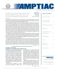
helicopters. PMC armor technology has since been transferred<br />
to ground vehicles, such as the High Mobility Multipurpose<br />
Wheeled Vehicle (HMMWV), which is shown in Figure 2.<br />
Figure 2. Armored HMMWV Deployed in Iraq[2].<br />
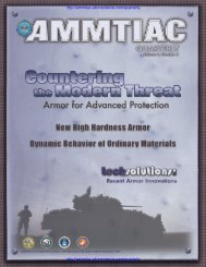
ENERGY ABSORPTION MECHANISMS<br />
Woven fiber mats and fiber-reinforced PMCs mitigate projectile<br />
energy in different ways. The amount of energy absorbed<br />
by fibers is largely dependent upon their strain to failure, as<br />
depicted in Figure 3a.[4] A fiber mat with high strength and<br />
high elongation to failure is thus expected to absorb energy via<br />
plastic deformation and drawing (stretching) of the fibers.<br />
Additionally, the strain in a fiber is equated to the impact<br />
velocity divided by the sonic velocity of the fiber (Equation<br />
1).[5]<br />
V<br />
ε = ––– c<br />
where,<br />
ε – strain<br />
V – impact velocity<br />
c – sonic velocity of the fiber<br />
Equation 1<br />
http://iac.dtic.mil/amptiac The <strong>AMPTIAC</strong> <strong>Quarterly</strong>, <strong>Vol</strong>ume 9, Number 2 3
Impact energy<br />
wave<br />
F/2<br />
θ<br />
T<br />
T<br />
θ<br />
F/2<br />
Reflected wave<br />
F<br />
T = fiber tensile load<br />
F = force resisting projectile<br />
F = 2Tsinθ<br />
Transmitted wave<br />
(a) Single fiber<br />
(b) Woven fiber<br />
Figure 3. Fiber Energy Absorption Mechanisms[4].<br />
The sonic velocity, in turn, is related to the fiber’s elastic<br />
modulus, as shown in Equation 2. A higher elastic modulus<br />
results in the impact energy wave traveling farther down the<br />
length of the fiber due to a greater sonic velocity, and thus a<br />
greater volume of fiber absorbs the projectile energy.<br />
E<br />
c = ––<br />
√ ρ<br />
where,<br />
E – elastic modulus<br />
ρ – density of the fiber<br />
Equation 2<br />
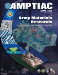
Spalled resin<br />
(a)<br />
Sheared fibers<br />
Drawn fibers<br />
Figure 4. Fiber-Reinforced PMC Energy Absorption<br />
Mechanisms[4].<br />
Delaminated composite<br />
(b)<br />
A woven fiber mat is effective at absorbing the impact load by<br />
dispersing the energy across a network of fibers, as depicted in<br />
Figure 3b.<br />
Once fibers are impregnated with a resin matrix their ability<br />
to deform may be hindered, and as a consequence they may<br />
absorb less energy. In fiber-reinforced PMCs, the fracture<br />
process is considered to happen in two phases. High velocity<br />
impact will cause localized compression of the composite, and<br />
subsequently shearing of fibers and spalling of resin, as depicted<br />
in Figure 4a. Once the projectile has slowed, the composite<br />
deforms causing fiber stretching, pullout, and delamination of<br />
composite layers (plies), as shown in Figure 4b. Stitching composite<br />
plies together or three dimensional fiber weaving may be<br />
used to reduce delamination and confine damage to a small<br />
area.[6] However, this may also result in an increase in fiber<br />
damage leading to a decrease in compressive strength after ballistic<br />
impact, and thus lower load carrying ability.<br />
HIGH PERFORMANCE FIBERS<br />
High performance fiber materials used in body and/or vehicle<br />
armors include S-glass, aramid, high molecular weight polyethylene<br />
and polybenzobisoxazole. A new fiber material, polypyridobisimidazole,<br />
shows promising results but has not yet been<br />
fully tested and validated for armor applications. Continuous<br />
fibers are characterized by “denier”, which is a measure of the<br />
weight, in grams, per 9000 meters (29,530 ft.) of fiber. Thus,<br />
when comparing fibers that have the same density, a smaller<br />
denier equates to a thinner fiber.<br />
Fibers can be woven together into a number of configurations,<br />
some of which are illustrated in Figure 5, to provide<br />
varying degrees of performance and flexibility. Fiber structures<br />
for armor applications have traditionally been in unidirectional,<br />
plain, or basket weave configurations. Unidirectional fiber<br />
layers may be rotated 90° with respect to adjacent layers to<br />
create a cross-ply fabric. Additional woven structures have been<br />
studied for armor applications, such as 3D structures to<br />
enhance the multi-hit capability of composites.<br />
(a) Plain Weave (b) Basket Weave (c) Triaxial Weave (d) 3D Braid<br />
(e) 3D Orthoganal Weave (f) 3D Triaxial Weave<br />
Figure 5. Woven Fiber Structures[7].<br />
4<br />
The <strong>AMPTIAC</strong> <strong>Quarterly</strong>, <strong>Vol</strong>ume 9, Number 2
S-Glass<br />
S-glass, composed of silica (SiO 2<br />
), alumina (Al 2<br />
O 3<br />
), and<br />
magnesia (MgO), is characterized by a strength that is roughly<br />
35 to 40% higher than that of E-glass.[8] S-2 Glass is a<br />
coated fiber, which has become the preferred fiber in many<br />
applications including armors. Its cost is significantly higher<br />
than E-glass, but its strength advantage, and consequently<br />
performance per unit weight advantage, usually warrants its<br />
selection for penetration resistance applications over E-glass.<br />
Relative to aramid fibers, S-2 Glass fibers generally have comparable<br />
ballistic performance, as measured by the V 50<br />
Probable<br />
Ballistic Limit Test (see sidebar), at a lower cost but higher<br />
weight. S-2 Glass has good fatigue and moisture resistance and<br />
a low creep rate, but can be susceptible to creep rupture. It can<br />
be used at elevated temperatures up to approximately<br />
1380°F.[9]<br />
Aramid<br />
Aramid fibers were developed during the 1960s and first introduced<br />
commercially by DuPont in the 1970s under the trade<br />
name Kevlar ®† . There are foreign companies that also produce<br />
commercially available aramid<br />
fibers, having the trade names<br />
Twaron ®‡ and Technora ®§ . The<br />
primary structure of aramid<br />
fibers is shown in Figure 6.<br />
Modifiers to the primary chain<br />
have been added over the years<br />
for property enhancements,<br />
resulting in the various aramid<br />
fibers available today. Kevlar<br />
29, Kevlar 49, Kevlar 129, and<br />
Kelvar KM2 are the DuPont<br />
aramid fibers that have been<br />
used most in armor applications.<br />
The Personnel Armor<br />
System for Ground Troops<br />
(PASGT) bullet-proof vests<br />
previously worn by military<br />
personnel were made from<br />
Kelvar 29. The Interceptor<br />
vests, which are currently being<br />
worn by soldiers in Iraq and<br />
Afghanistan, are made from<br />
Kelvar KM2 fiber.<br />
Aramid fibers exhibit a<br />
decrease in tensile strength<br />
when exposed to heat or moisture. At temperatures up to<br />
355°F, a strength loss of ≤ 20% occurs.[10] Strength losses of<br />
≤ 5% at high humidity and room temperature and ≤ 10%<br />
under hot water conditions have been observed; however, the<br />
strength degradation appears to be reversible. The operating<br />
temperature range is -420 to 320°F, with an onset of thermal<br />
degradation occurring at about 840°F.[11,12] Aramid fibers<br />
are vulnerable to damage from ultraviolet light, with a 49%<br />
loss in strength measured after exposure to a Florida environment<br />
for 5 weeks.[11] Strong acid and alkaline environments<br />
will also attack aramid fibers. The fibers have good fatigue<br />
O<br />
C<br />
C<br />
C<br />
C<br />
N<br />
O<br />
NH<br />
N<br />
C<br />
C<br />
O<br />
N<br />
Figure 6. Aramid Chemical Structure.<br />
C<br />
C<br />
Figure 7. PBO Chemical Structure.<br />
C<br />
C<br />
C<br />
C<br />
C<br />
C<br />
C<br />
C<br />
N<br />
C<br />
C<br />
C<br />
C<br />
C<br />
H<br />
N<br />
O<br />
resistance, low creep rates, and are less susceptible to creep<br />
rupture than S-2 Glass fibers. Aramid fibers do not naturally<br />
bond well to resins, so they are usually chemically coated<br />
(sized) prior to their incorporation in composites.<br />
High Molecular Weight Polyethylene<br />
High molecular weight polyethylene (HMWPE) has a simple<br />
structure consisting of a repeating ethylene unit [CH 2<br />
-CH 2<br />
] n<br />
.<br />
Two commercially produced HMWPE fibers are Spectra ®|| and<br />
Dyneema ®# . HMWPE fibers have the lowest density of all<br />
fibers currently used for armor applications, with a V 50<br />
that is<br />
higher than both S-2 Glass and aramid fibers per equivalent<br />
weight. Their limitations include a lower operating temperature<br />
range, creep susceptibility and poor compressive strength.<br />
HMWPE fibers have a maximum processing temperature of<br />
250°F, limiting the choice of matrix materials to low temperature<br />
curing thermosets or selected thermoplastic resins.[13]<br />
Polybenzobisoxazole<br />
Polybenzobisoxazole (PBO) fibers are a result of the US Air<br />
Force’s research during the 1980s that looked into developing<br />
a stronger fiber than aramids.<br />
N<br />
NH<br />
C<br />
C<br />
C<br />
C<br />
C<br />
OH<br />
Figure 8. M5 Chemical Structure.<br />
C<br />
C<br />
C<br />
C<br />
C<br />
C<br />
C<br />
C<br />
C<br />
C<br />
C<br />
C<br />
C<br />
N<br />
H<br />
C<br />
C<br />
OH<br />
n<br />
n<br />
n<br />
[12] The repeat unit of PBO,<br />
a rigid-rod structure, is shown<br />
in Figure 7. PBO fibers have<br />
very high tensile strength<br />
properties, achieving better<br />
penetration resistance than<br />
the HMWPE fibers, but suffer<br />
from low compressive<br />
strength like HMWPE. The<br />
decomposition temperature<br />
of PBO fibers is about<br />
1025°F, compared to 840°F<br />
for aramid fibers.[12]<br />
A commercial PBO fiber<br />
is currently on the market<br />
under the trade name<br />
Zylon ®** . Zylon has been<br />
shown to undergo tensile<br />
strength degradation in elevated<br />
temperatures and moisture,<br />
and when exposed to ultraviolet<br />
and visible light.[14] A<br />
40% loss in strength can occur<br />
at a temperature of 176°F and<br />
80% relative humidity. The<br />
strength loss after 6 months exposure to daylight is roughly<br />
65%. One theory for the strength loss incurred involves the<br />
method in which PBO fibers are being fabricated.[15] The<br />
fibers are spun from a solution containing polyphosphoric acid.<br />
Although the fibers are washed, dried, and heat treated, some<br />
trace amounts of acid may remain on the fibers. The residual<br />
acid combined with humid environments, sunlight or oxygen<br />
can cause significant degradion of the fiber strength. Further<br />
investigations into the strength loss of PBO fibers are being<br />
conducted by the National Institute of Standards and<br />
Technology, as directed by the National Institute of Justice.[16]<br />
http://iac.dtic.mil/amptiac The <strong>AMPTIAC</strong> <strong>Quarterly</strong>, <strong>Vol</strong>ume 9, Number 2 5
Table 1. Typical Fiber Properties. a<br />
Glass<br />
Aramid<br />
HMWPE<br />
PBO<br />
PIPD<br />
Fiber Density (g/cm 3 ) Elastic Modulus (GPa) Tensile Strength (MPa) Strain to Failure (%)<br />
S-glass[10] 2.48 90 4400 5.7<br />
Technora[10] 1.39 70 3000 4.4<br />
Twaron[10] 1.45 121 3100 2.0<br />
Kevlar 29[17] 1.44 70 2965 4.2<br />
Kevlar 129[17] 1.44 96 3390 3.5<br />
Kevlar 49[17] 1.44 113 2965 2.6<br />
Kelvar KM2[18] 1.44 70 3300 4.0<br />
Spectra 900[17] 0.97 73 2400 2.8<br />
Spectra 1000[17] 0.97 103 2830 2.8<br />
Spectra 2000[19] 0.97 124 3340 3.0<br />
Dyneema[20] 0.97 87 2600 3.5<br />
Zylon AS[20] 1.54 180 5800 3.5<br />
Zylon HM[20] 1.56 270 5800 2.5<br />
M5 (2001 sample)[21] 1.70 271 3960 1.4<br />
M5 (goal)[21] - 450 9500 2.5<br />
aThe data presented are typical values and thus will vary dependent upon fiber denier.<br />
3000<br />
2500<br />
0.30 cal. Fragment Simulating Projectile<br />
3000<br />
2500<br />
0.30 cal. Fragment Simulating Projectile<br />
V 50 (ft/s)<br />
2000<br />
1500<br />
1000<br />
Spectra 1000,<br />
650 denier-plain weave<br />
Kevlar 29,<br />
1500 denier-basket weave<br />
500<br />
0 1 2 3 4 5 6 7 8<br />
Areal Density (lb/ft 2 )<br />
V 50 (ft/s)<br />
2000<br />
1500<br />
1000<br />
500<br />
Spectra 1000,<br />
650 denier-plain weave<br />
Kevlar 29,<br />
1500 denier-basket weave<br />
0 0.2 0.4 0.6 0.8 1 1.2<br />
Thickness (in.)<br />
(a) V 50 versus Areal Density<br />
(b) V 50 versus Thickness<br />
Figure 9. V 50 Comparison of Fabrics[18].<br />
Polypyridobisimidazole<br />
A new high performance fiber – polypyridobisimidazole<br />
(PIPD), denoted M5 ®†† – has been developed at Akzo <strong>No</strong>bel<br />
and shows promising results. Similar to PBO, it is a rigid-rod<br />
structure as shown in Figure 8. Due to strong intermolecular<br />
hydrogen bonding, however, its compressive strength is significantly<br />
improved over that of PBO fibers. Its decomposition<br />
temperature is about 985°F, which is close to that of PBO<br />
fibers.[12] The fabrication technologies for M5 fibers are still<br />
in developmental phases, as some properties of the fibers fall<br />
short of their theoretical potential.<br />
Comparison of High Performance Fibers<br />
As discussed in the section on energy absorption mechanisms,<br />
the major properties used to assess probable ballistic performance<br />
are the tensile strength, elastic modulus, and strain to<br />
failure. Table 1 provides a general comparison of these properties,<br />
along with density, for the various high performance<br />
fiber materials. <strong>No</strong>te the difference in tensile strength<br />
between Kevlar 29 used for the old PASGT vests and Kelvar<br />
KM2 used for the new Interceptor vests. The HMWPE and<br />
aramid fibers are used as fabrics for flexible military body<br />
armors, whereas S-2 Glass is used in rigid composite armor<br />
applications. PBO fibers have not been used for military<br />
applications, and M5 is still in developmental stages. Both<br />
HMWPE and aramid fibers are also used in fiber-reinforced<br />
PMCs for rigid armor applications. Figure 9a indicates that<br />
Spectra 1000 fabrics provide a higher V 50<br />
PBL at a lighter<br />
weight than Kevlar 29. Figure 9b shows that Spectra 1000<br />
provides a higher level of protection at the same thickness as<br />
Kevlar 29 up until approximately 0.7 inches, where the level<br />
of protection provided by the two fibers is approximately<br />
equal. At thicknesses greater than 0.7 inches Kevlar 29 outperforms<br />
Spectra 1000 in terms of ballistic performance.<br />
RESINS<br />
Resins for fiber-reinforced polymer matrix composite armors<br />
can be either thermoplastics or thermosets. In general, thermoplastics<br />
offer greater impact resistance and processibility,<br />
but lack the thermal and chemical resistance of thermosets.<br />
6<br />
The <strong>AMPTIAC</strong> <strong>Quarterly</strong>, <strong>Vol</strong>ume 9, Number 2
Table 2. Thermoset Resin Comparison[23].<br />
Resin Advantages Disadvantages<br />
Polyester<br />
Vinyl Ester<br />
Epoxy<br />
•Low cost<br />
• Easy to process<br />
• Good chemical resistance<br />
• Good moisture resistance<br />
•Fast cure time<br />
•Room temperature cure<br />
•Low cost<br />
• Easy to process<br />
•Low viscosity<br />
•Room temperature cure<br />
• Moisture resistant<br />
• Good mechanical properties<br />
•Excellent mechanical properties<br />
(superior to vinyl esters)<br />
• Good chemical resistance<br />
• Good heat resistance<br />
• Good adhesive properties with a<br />
large variety of substrates<br />
• Moisture resistant<br />
•Variety of compositions available<br />
• Good fracture toughness<br />
• Flammable<br />
•Toxic smoke upon combustion<br />
• Average mechanical properties<br />
• Flammable<br />
• Smoke released upon combustion<br />
•Expensive<br />
•Requires high processing temperatures<br />
to achieve good properties<br />
Thermoplastics have therefore found limited<br />
use in military armor systems in the form of<br />
body armor components. Spectra Shield ®‡‡ ,<br />
however, is a commercial product that uses<br />
cross-ply fabrics sandwiched between layers<br />
of thermoplastic resins.[22] Vehicle armors<br />
primarily consist of one of the high performance<br />
fiber materials discussed earlier in this<br />
article along with an epoxy, polyester, vinyl<br />
ester, or phenolic thermoset resin.<br />
Epoxy, polyester, and vinyl ester are the primary<br />
resin materials for armor-grade composites,<br />
while phenolic resins are used in applications<br />
that require fire, smoke, and toxicity<br />
(FST) control. In some armor composite systems,<br />
one of the three primary resins is used<br />
for ballistic protection while a phenolic composite<br />
backplate provides FST resistance.<br />
Epoxies provide the best structural characteristics<br />
of all the resins, and are available in a<br />
wide range of formulations. They have excellent<br />
mechanical properties and good adhesion<br />
to numerous materials, but require high processing<br />
temperatures to attain a high level of<br />
The V 50<br />
PBL as defined by MIL-STD-662F, V 50<br />
Ballistic Test for Armor is the most common<br />
method for assessing lightweight armor materials for ballistic performance.[i] The final state of<br />
a witness plate placed behind the armor panel determines the experimental outcome of the ballistic<br />
test, as shown in the figure. Two situations may occur as a result of the ballistic test:<br />
• Complete penetration (evidenced by visibility of light through the witness plate) takes place<br />
when the witness plate is completely perforated by projectile or plate spall.<br />
•Partial penetration occurs if no perforation is observed (even if test panel may be perforated)<br />
through the “witness plate.”<br />
The area corresponding to a velocity range causing a<br />
mixture of partial and complete penetration is the Zone<br />
of Mixed Results (ZMR).<br />
The V 50<br />
may be defined as the average of an equal<br />
number of highest partial penetration velocities and the<br />
lowest complete penetration velocities which occur<br />
within a specified velocity spread. A 0.020 inch (0.51<br />
mm) thick 2024-T3 sheet of aluminum is placed 6±1/2<br />
inches (152±12.7 mm) behind and parallel to the target<br />
to witness complete penetrations. <strong>No</strong>rmally at least<br />
two partial and two complete penetration velocities are<br />
Armor<br />
PARTIAL<br />
Penetration<br />
Witness plate is intact<br />
Witness<br />
Plate<br />
used to compute the V 50<br />
value. Four, six, and ten-round ballistic limits are frequently used. The<br />
maximum allowable velocity span is dependent on the armor material and test conditions.<br />
Maximum velocity spans of 60, 90, 100, and 125 feet per second (ft/s) (18, 27, 30, and 38<br />
m/s) are frequently used. Disadvantages with this test are the wide latitude of V 50<br />
values and<br />
the absence of specification for specimen size.<br />
REFERENCES<br />
[i] MIL-STD-662F, V 50<br />
Ballistic Test for Armor, US Army Research Laboratory, Weapons & Materials<br />
Research Directorate, Aberdeen Proving Ground, MD, December 1997<br />
[ii] J.H. Graves and Captain H. Kolev, Joint Technical Coordinating Group on Aircraft Survivability<br />
Interlaboratory Ballistic Test Program, Army Research Laboratory, June 1995<br />
COMPLETE<br />
Penetration<br />
Witness plate is penetrated<br />
by projectile or plate spall<br />
V 50<br />
Probable Ballistic<br />
Limit (PBL)<br />
Schematic Presentations of<br />
Partial and Complete<br />
Penetrations[ii].<br />
http://iac.dtic.mil/amptiac The <strong>AMPTIAC</strong> <strong>Quarterly</strong>, <strong>Vol</strong>ume 9, Number 2 7
V 50 (ft/s)<br />
3500<br />
3000<br />
2500<br />
2000<br />
1500<br />
1000<br />
500<br />
0.20<br />
0.22 cal. Fragment Simulating Projectile 0.50 cal. Fragment Simulating Projectile<br />
FEM<br />
EXP<br />
0.16<br />
Delamination Diameter (m)<br />
0.12<br />
0.08<br />
0.04<br />
Stitched<br />
Stitched<br />
0<br />
Plain<br />
Weave<br />
Triaxial<br />
Weave<br />
3D<br />
Orthogonal<br />
Weave<br />
3D<br />
Triaxial<br />
Weave<br />
3D<br />
Braided<br />
Weave<br />
Figure 10. Ballistic Performance Comparison of S-2 Glass-Based<br />
Composite of Weave Structures[24].<br />
0.00<br />
Vinyl Ester<br />
Epoxy<br />
Figure 11. Effect of Stitching on Ballistic Performance of<br />
S-2 Glass Fiber-Reinforced Composites[6].<br />
quality. Polyesters and vinyl esters are low cost, easily processed<br />
composites with above average mechanical properties, but have<br />
low compressive strengths. As a result of this deficiency, they<br />
are normally relegated to non-structural applications.<br />
Phenolics, like the polyesters, have low compressive strength<br />
properties, but provide higher temperature capabilities and low<br />
smoke generation upon combustion.<br />
Ease of processing and the potential release of toxic chemicals<br />
are concerns with composites. Processing methods, such as resin<br />
transfer molding, require resin materials to have low viscosities<br />
in order for the finished product to have a low porosity, and thus<br />
good performance. In the case of higher viscosity materials, like<br />
epoxies, high processing temperatures and/or additives are used<br />
to produce the required low viscosity for processing. High processing<br />
temperatures, however, correspond to higher costs and<br />
may also limit fiber selection, while additives can produce toxic<br />
byproducts. The trade-offs of performance, ease of processing,<br />
and costs are summarized in Table 2 for the three structural<br />
resins. In most applications, vinyl ester resins have replaced<br />
polyester resins as they are similar in many properties, but with<br />
the added benefit of having superior mechanical properties.<br />
FIBER-REINFORCED PMC ARMOR<br />
The performance of fiber-reinforced PMC armors not only<br />
depends upon the fiber and resin material properties, but also<br />
the fiber structure, fiber volume, fiber compatibility with the<br />
resin, and additives. Most commercial fiber composites for<br />
armors consist of unidirectional, plain, or basket weave fiber<br />
structures. Weaving fibers does not generally improve the<br />
penetration resistance in composites, because the fibers are<br />
confined by the resin and the energy can not be effectively<br />
transferred to adjacent fibers as is the case of fiber mats. Three<br />
dimensional weaves limit delamination and thus improve<br />
multi-hit performance of composites. Figure 10 compares the<br />
ballistic performance of various woven S-2 Glass fiber composites<br />
subjected to a 0.22 caliber fragment simulating projectile<br />
(FSP) using finite element modeling (FEM) and experiments<br />
(EXP). Through-the-thickness stitching of composite plies is<br />
another means of limiting delamination problems, as shown in<br />
Figure 11 for S-2 Glass composites tested with a 0.50 caliber<br />
fragment simulating projectile at 1550 feet per second.<br />
The ballistic performance of fiber-reinforced PMC armors is<br />
largely attributed to the fibers. Maximizing fiber volume in a<br />
5000<br />
0.30 cal. Fragment Simulating Projectile<br />
5000<br />
0.30 cal. Fragment Simulating Projectile<br />
4000<br />
4000<br />
V 50 (ft/s)<br />
3000<br />
V 50 (ft/s)<br />
3000<br />
2000<br />
1000<br />
S-2 Glass, no background data<br />
0<br />
0 2 4 6 8 10 12<br />
Areal Density (lb/ft 2 )<br />
(a) V 50 versus Areal Density<br />
Spectra 1000, 650 denier-plain weave<br />
KM2, 850 denier-plain weave<br />
Kevlar 29, 1500 denier-basket weave<br />
2000<br />
Figure 12. General Comparison of Fiber-Reinforced PMC Armors[18].<br />
Spectra 1000, 650 denier-plain weave<br />
1000<br />
KM2, 850 denier-plain weave<br />
Kevlar 29, 1500 denier-basket weave<br />
S-2 Glass, no background data<br />
0<br />
0 0.2 0.4 0.6 0.8 1.0<br />
Thickness (in.)<br />
(b) V 50 versus Thickness<br />
8<br />
The <strong>AMPTIAC</strong> <strong>Quarterly</strong>, <strong>Vol</strong>ume 9, Number 2
composite using the top performance weave structure will<br />
therefore optimize the ballistic performance of composites.<br />
Most PMC armors have fiber volumes in the vicinity of 60 percent.<br />
Coupling agents which help bond fibers to resins can<br />
influence penetration resistance. For armor applications, fiber<br />
pull-out is beneficial under impact loading, since the failure<br />
mechanism absorbs energy. Additives, in some cases, are introduced<br />
primarily to increase fracture toughness of the composite.<br />
Thermoplastics and rubber materials may be used for this<br />
purpose. Figure 12 is a comparison of typical V 50<br />
data of some<br />
fiber-reinforced PMC armor materials, and it shows that the<br />
performance of the composite materials reflects the performance<br />
of the fibers previously displayed in Figure 9.<br />
SUMMARY<br />
High performance fibers provide the means to produce lightweight<br />
fabrics for body armor as well as lightweight PMCs for<br />
vehicle armor. The availability of different high performance<br />
fibers and resins along with the ability to tailor fibers allows<br />
versatility in designing fiber-reinforced PMC armors. The<br />
development of improved lightweight armor materials will<br />
continue to play an important role in the transformation of US<br />
military forces to meet present and future threats.<br />
NOTES & REFERENCES<br />
Citation of companies and product trade names does not constitute an<br />
endorsement or approval of the use thereof.<br />
* Interceptor is a registered trademark of Point Blank Body Armor,<br />
Inc.<br />
† Kevlar is a registered trademark of the E.I. du Pont de Nemours and<br />
Company<br />
‡ Twaron is a registered trademark of the Teijin Company<br />
§ Technora is a registered trademark of the Teijin Company<br />
|| Spectra is a registered trademark of the Allied Signal Corporation<br />
# Dyneema is a registered trademark of the DSM High Performance<br />
Fibers Company<br />
** Zylon is a registered trademark of the Toyobo Company<br />
†† M5 is a registered trademark of Magellan Systems International<br />
‡‡ Spectra Shield is a registered trademark of Honeywell International,<br />
Inc.<br />
[1] R.E. Wittman and R.F. Rolsten, Armor – of Men and Aircraft, 12th<br />
National SAMPE Symposium, SAMPE, 1967<br />
[2] Fort Hood, US Army, (http://www.hood.army.mil/)<br />
[3] The Interceptor System, US Marine Corps, (http://www.<br />
marines.mil/marinelink/image1.nsf/lookup/<strong>2005</strong>32317129?<br />
opendocument)<br />
[4] P.J. Hogg, Composites for Ballistic Applications, Journal of<br />
Composites Processing, CPA, Bromsgrove U.K., March 2003,<br />
(http://www.composites-proc-assoc.co.uk/view.php?pid =24)<br />
[5] H.H. Yang, Kevlar Aramid Fiber, John Wiley & Sons, 1993<br />
[6] B.K. Fink, A.M. Monib, and J.W. Gillespie Jr., Damage Tolerance<br />
of Thick-Section Composites Subjected to Ballistic Impact, Army<br />
Research Laboratory, ARL-TR-2477, May 2001<br />
[7] F. Ko and A. Geshury, Textile Preforms for Composite Materials<br />
Processing, <strong>Advanced</strong> Materials and Processes Information Analysis<br />
Center, AMPT-19, August 2002<br />
[8] S.J. Walling, S-2 Glass Fiber: Its Role in Military Applications,<br />
International Conference on Composite Materials, Metallurgical<br />
Society of AIME, August 1985, pp. 443-456<br />
[9] F.T. Wallenberger, Introduction to Reinforcing Fibers, ASM<br />
Handbook – <strong>Vol</strong>ume 21: Composites, ASM International, 2001<br />
[10] K.K. Chang, Aramid Fibers, ASM Handbook – <strong>Vol</strong>ume 21:<br />
Composites, ASM International, 2001<br />
[11] Fibre Reinforcements for Composite Materials, ed. A.R. Bunsell,<br />
Elsevier Science Publishers, 1988<br />
[12] D.J. Sikkema, M.G. <strong>No</strong>rtholt, and B. Pourdeyhimi, Assessment of<br />
New High-Performance Fibers for <strong>Advanced</strong> Applications, MRS Bulletin,<br />
<strong>Vol</strong>. 28. <strong>No</strong>. 8, August 2003, pp. 579-584<br />
[13] D.J. Viechnicki, A.A. Anctil, D.J. Papetti, and J.J. Prifti,<br />
Lightweight Armor – A Status Report, US Army Materials Technology<br />
Laboratory, MTL-TR-89-8, January 1989<br />
[14] PBO Fiber Zylon, Technical Information (Revised 2001.9),<br />
Toyobo Co., Ltd.<br />
[15] X. Hu and A.J. Lesser, Post-treatment of Poly-p-phenylenebenzobisoxazole<br />
(PBO) Fibers Using Supercritical Carbon Dioxide, University<br />
of Massachusetts, (http://www.policeone.com/policeone/data/images/<br />
upload/PostTreatmentPBO.pdf)<br />
[16] Status Report to the Attorney General on Body Armor Safety<br />
Initiative Testing and Activities, National Institute of Justice, March<br />
2004, (http://vests.ojp.gov/docs/ArmorReportWithPress.pdf?popup<br />
Window=Y)<br />
[17] Fabric Handbook, Hexcel Fabrics, Austin TX<br />
[18] L.A. Twisdale, R.A. Frank Jr. and F.M. Lavelle, Airmobile Shelter<br />
Analysis <strong>Vol</strong>ume II, Air Force Civil Engineering Support Agency, ESL-<br />
TR-92-74, February 1994<br />
[19] Manufacturer Data, Honeywell<br />
[20] Manufacturer Data, Toyobo<br />
[21] P.M. Cunniff, M.A. Auerbach, E. Vetter and D.J. Sikkema, High<br />
Performance “M5” Fiber for Ballistics/Structural Composites, 23rd Army<br />
Science Conference, 2004<br />
[22] Honeywell International, Inc., (http://spectrafiber.com)<br />
[23] E.F. Gillio, Co-injection Resin Transfer Molding of Hybrid<br />
Composites, Center for Composite Materials, University of Delaware,<br />
CCM 97-23, 1997<br />
[24] C-F. Yen and A.A. Caiazzo, 3D Woven Composites for New and<br />
Innovative Impact and Penetration Resistant Systems, US Army Research<br />
Office, July 2001<br />
http://iac.dtic.mil/amptiac The <strong>AMPTIAC</strong> <strong>Quarterly</strong>, <strong>Vol</strong>ume 9, Number 2 9
PRODUCTS<br />
Our complete product catalog is available online at<br />
http://amptiac.alionscience.com/products<br />
Textile Preforms<br />
for Composite Material Technology<br />
This publication is the first and only<br />
one of its kind – A panoramic and<br />
thorough examination of fiber/textile<br />
perform technology and its critical<br />
role in the development and manufacture<br />
of high-performance composite<br />
materials. This product was prepared<br />
in collaboration with Drexel University<br />
and authored by Dr. Frank Ko, the<br />
Director of Drexel’s Fibrous Materials<br />
Research Center. Dr. Ko is one the<br />
world’s foremost authorities on fibrous<br />
preforms and textile technology.<br />
Order Code: AMPT-19<br />
Price: $100 US, $150 <strong>No</strong>n-US<br />
Computational Materials Science (CMS)<br />
A Critical Review and Technology Assessment<br />
<strong>AMPTIAC</strong> surveyed DOD, goverment,<br />
and academic efforts studying<br />
materials science by computational<br />
methods and from this research compiled<br />
this report. It provides an indepth<br />
examination of CMS and<br />
describes many of the programs,<br />
techniques, and methodologies being<br />
used and developed. The report was<br />
sponsored by Dr. Lewis Sloter, Staff<br />
Specialist, Materials and Structures,<br />
in the Office of the Deputy Undersecretary<br />
of Defense for Science and<br />
Technology.<br />
BONUS MATERIAL: Dr. Sloter also hosted a workshop<br />
(organized by <strong>AMPTIAC</strong>) in April 2001 for the<br />
nation’s leaders in CMS to discuss their current programs<br />
and predict the future of CMS. The workshop<br />
proceedings comprise all original submitted materials<br />
for the workshop – presentations, papers, minutes,<br />
and roundtable discussion highlights and are included<br />
with purchase of the above report.<br />
Order Code: AMPT-25<br />
Price: $65 US, $95 <strong>No</strong>n-US<br />
Blast and Penetration Resistant Materials<br />
This State-of-the-Art Report compiles<br />
the recent and legacy DOD<br />
unclassified data on blast and penetration<br />
resistant materials (BPRM)<br />
and how they are used in structures<br />
and armor. Special attention was<br />
paid to novel combinations of<br />
materials and new, unique uses for<br />
traditional materials. This report<br />
was sponsored by Dr. Lewis Sloter,<br />
Staff Specialist, Materials and<br />
Structures, in the Office of the<br />
Deputy Undersecretary of Defense<br />
for Science & Technology.<br />
BONUS MATERIAL: Dr. Sloter also hosted a workshop<br />
in April, 2001 (organized by <strong>AMPTIAC</strong>) for selected<br />
experts in the field of BPRM and its application. The<br />
workshop focused on novel approaches to structural<br />
protection from both blast effects and penetration phenomena.<br />
Some areas covered are: building protection<br />
from bomb blast and fragments, vehicle protection,<br />
storage of munitions and containment of accidental<br />
detonations, and executive protection. The proceedings<br />
of this workshop are included with purchase of<br />
the above.<br />
Order Code: AMPT-26<br />
Price: $115 US, $150 <strong>No</strong>n-US<br />
Applications of Structural Materials for Protection<br />
from Explosions<br />
This State-of-the-Art Report provides an<br />
examination of existing technologies for<br />
protecting structures from explosions.<br />
The report does not discuss materials<br />
and properties on an absolute scale;<br />
rather, it addresses the functionality of<br />
structural materials in the protection<br />
against blast. Each chapter incorporates<br />
information according to its relevance to<br />
blast mitigation. For example, the section<br />
on military structures describes concrete<br />
in arches, and concrete in roof<br />
beams for hardened shelters. The discussion<br />
on concrete is not limited to materials only; rather, it addresses the<br />
issue of structural components that incorporate concrete, and describes<br />
the materials that work in concert with the concrete to produce a blastresistant<br />
structure. The report also illustrates various materials used for<br />
concrete reinforcement.<br />
Order Code: AMPT-21<br />
Price: $100 US, $150 <strong>No</strong>n-US<br />
Product Information and Ordering<br />
Phone Online Email<br />
(315)339-7047 http://amptiac.alionscience.com/products gnash@alionscience.com<br />
10<br />
The <strong>AMPTIAC</strong> <strong>Quarterly</strong>, <strong>Vol</strong>ume 9, Number 2
Material<br />
E A S E<br />
30<br />
<strong>AMPTIAC</strong><br />
Benjamin D. Craig<br />
<strong>AMPTIAC</strong><br />
Rome, NY<br />
Material Failure Modes, Part II<br />
A Brief Tutorial on Impact, Spalling, Wear, Brinelling, Thermal Shock, and Radiation Damage<br />
This issue of MaterialEASE is Part Two of a three part series on material failure modes. MaterialEASE 29, published in <strong>Vol</strong>ume<br />
9, Number 1 of the <strong>AMPTIAC</strong> <strong>Quarterly</strong>, introduced the concept of material failure modes and covered fracture, ductile failure,<br />
elastic deformation, creep, and fatigue. This article continues the discussion with brief descriptions of impact, spalling, wear,<br />
brinelling, thermal shock, and radiation damage. The next MaterialEASE article will complete the series on material failure<br />
modes, and the three articles taken together will make a valuable desk reference for any professional making material selection<br />
and design decisions. - Editor<br />
INTRODUCTION<br />
The purpose of this article is to briefly introduce several material<br />
failure modes. A better understanding of these failure mechanisms<br />
will enable more appropriate decisions when selecting<br />
materials for a particular application. Even a basic knowledge<br />
and awareness can help design engineers to be better equipped in<br />
delaying or preventing the failure of a material or component.<br />
Failure can occur in systems with moving or non-moving<br />
parts. In systems with moving parts, friction often leads to material<br />
degradation such as wear, and collisions between two components<br />
can result in surface or more extensive material damage.<br />
Systems with non-moving parts are also prone to material failure,<br />
especially when certain types of materials are subjected to<br />
extreme temperature changes or to high energy radiation environments.<br />
Material failure often manifests itself in the form of cracking,<br />
but it can also appear as material disintegration, mechanical<br />
property degradation, or even physical deformation. For instance,<br />
impact failure can occur by fracture, deformation, or material<br />
disintegration, while radiation damage can cause a severe degradation<br />
of a material’s properties. These failure modes, as well as<br />
spalling, wear, brinelling, and thermal shock are described<br />
throughout the rest of this article.<br />
IMPACT<br />
The collision of two masses, one of which can be stationary, causes<br />
a sudden increase in stress or an intense change in pressure<br />
(as in an explosive blast), and may result in impact failure. This<br />
shock loading can cause permanent deformation or fracture to<br />
one or both of the colliding bodies, which can render that material<br />
unable to perform its intended function. Sudden impact<br />
loading can result in shock waves which induce localized stresses<br />
and strains causing mechanical damage to the material. There<br />
are several different types of impact failure including impact<br />
fracture, impact deformation, impact wear, impact fretting, and<br />
impact fatigue. Each of these will be discussed in some detail in<br />
the following sections.<br />
Impact Fracture<br />
The most extreme consequence of sudden shock loading results<br />
in fracture. This can be a catastrophic failure mode, as it occurs<br />
rapidly under the load of a sudden impact, and it is common in<br />
brittle materials, such as ceramics. For example, when a ceramic<br />
armor tile is hit with a projectile it likely will sustain multiple<br />
fractures. This failure mode is in contrast to impact deformation.<br />
Impact Deformation<br />
The energy imparted to a material during sudden shock loading<br />
can be absorbed through deformation. Plastic deformation<br />
caused by this sudden shock loading can preclude a structure<br />
from performing its intended function. This is a failure mode<br />
known as impact deformation, and typically occurs in ductile<br />
materials, such as metals.<br />
Impact Wear<br />
Impact wear occurs when a material is repeatedly impacted by<br />
another solid mass causing a gradual deterioration of the surface.<br />
The impact of large or small masses or particles can cause<br />
deformation to the material being impacted. This deformation<br />
can result in the ejection of particles from the material’s surface,<br />
or the formation of near-surface cracks that under repeated<br />
impact can cause pieces of the surface to fracture (see description<br />
of surface fatigue wear in this article). In the case of repeated<br />
impact by particles that are very small relative to the size of the<br />
material being impacted, the wear that ensues could be considered<br />
erosive wear. Erosive wear is the continuous deterioration<br />
of a material by a fluid carrying solid particles. When the fluid<br />
is traveling in a direction that is normal to the surface of the<br />
material, it can be considered impact wear.<br />
http://iac.dtic.mil/amptiac The <strong>AMPTIAC</strong> <strong>Quarterly</strong>, <strong>Vol</strong>ume 9, Number 2 11
Material<br />
E A S E<br />
Impact Fretting<br />
Impact fretting is a fretting damage mechanism (see section on<br />
fretting wear in this article) where the two contacting bodies<br />
become physically disengaged momentarily and suddenly resume<br />
contact. This occurs while the two materials continue their relative<br />
sliding motion causing both fretting and impact damage.<br />
This sudden separation and subsequent impact can cause an<br />
increase in the fretting wear rate, as an additional damage mechanism<br />
is employed.<br />
Impact Fatigue<br />
Impact fatigue is a failure mode obviously related to impact<br />
damage, but is briefly described in the section on fatigue failure<br />
modes published in MaterialEASE 29, <strong>AMPTIAC</strong> <strong>Quarterly</strong><br />
<strong>Vol</strong>ume 9, Number 1.[1]<br />
SPALLING<br />
Spalling is the deterioration of a component as fragments from<br />
the surface break free from the material. This phenomenon can<br />
occur through several mechanisms including the formation and<br />
propagation of fatigue cracks underneath the surface. This<br />
mechanism is related to the surface fatigue mechanism, which<br />
is discussed in the following section. Another mechanism that<br />
leads to spalling involves the propagation of shock waves through<br />
to the opposite side of a material after being impacted, which<br />
results in significant localized stress and consequently cracking<br />
near the surface. This sub-surface cracking causes surface fractures<br />
and particles to be dislodged from the material’s surface.<br />
Similarly, thermal shock can cause spalling failure (see section<br />
on thermal shock in this article). Spalling can occur in metals<br />
or ceramics or even surface coatings; it often occurs in armor<br />
materials, gear teeth, and bearings. Figure 1 shows spalling failure<br />
of a gear tooth.<br />
Figure 1. Spalling Failure on the<br />
Surface of a Gear Tooth Caused by<br />
Surface Fatigue[2].<br />
WEAR<br />
Wear is a general term used to describe the deterioration of a<br />
material’s surface caused by frictional forces generated as a result<br />
of contact between two surfaces that are moving in relation to one<br />
another. Temperature has an effect on the wear rate (rate at which<br />
a material deteriorates under frictional forces) because friction<br />
generates heat, which in turn can affect the microstructure of<br />
the material and make it more susceptible to deterioration.<br />
Components such as bearings, cams, and gears are often<br />
susceptible to wear. There are several different types of wear,<br />
including adhesive wear, abrasive wear, corrosive wear, surface<br />
fatigue wear, impact wear, and fretting wear. Most of these will be<br />
discussed in some detail in the following sections.<br />
Minimizing or protecting a material’s surface from wear can<br />
be accomplished through several methods including the use of<br />
lubricants and surface treatments.[3] Selecting a material that<br />
is resistant to wear, such as one having high hardness (e.g.<br />
ceramics), is also a good method to prevent excessive wear.<br />
Alternatively, hard coatings such as tungsten-carbide-cobalt can<br />
be used to augment the hardness of a component having a relatively<br />
soft surface. Surface or heat treatments can also be used to<br />
increase the hardness or smoothness of the surface. Exampes<br />
include carburizing and superfinishing, which is described in<br />
<strong>Vol</strong>ume 7, Number 1 of the <strong>AMPTIAC</strong> <strong>Quarterly</strong>.[4]<br />
Adhesive Wear<br />
Adhesive wear occurs between two surfaces in relative motion as<br />
the result of high contact stresses, which are generated because<br />
of the inherent roughness of material surfaces. <strong>No</strong> matter how<br />
finely polished a surface is, two materials in contact with each<br />
other do not mate completely. This allows localized areas on the<br />
surface to sustain a greater percentage of a mechanical load,<br />
while the areas that are not in contact with the opposing surface<br />
absorb none of the mechanical load. In adhesive wear, the peaks<br />
on the adjacent surfaces that do come into contact will plastically<br />
deform under pressure and form atomic bonds at the interface<br />
(in some cases this is considered solid-phase welding). As the<br />
relative motion between the surfaces continues, the shear stress<br />
at the now atomically bonded contact point increases until the<br />
shear strength limit of one of the materials is reached and the<br />
contact point is broken bringing with it a piece of the opposing<br />
surface. The broken material can then either be released as debris<br />
or remain bonded to the other material’s surface. This process<br />
is demonstrated in Figure 2. Adhesive wear is also known as<br />
scoring, scuffing, galling or seizing (galling and seizure are<br />
described briefly below).[3,5]<br />
High hardness and low strength are desirable properties for<br />
applications requiring resistance to adhesive wear. However, these<br />
properties are somewhat mutually exclusive, which makes composite<br />
materials desirable for such applications. Examples of<br />
resistant monolithic materials include low strength, high ductility<br />
polymers and high hardness, low density ceramics. Sintered<br />
copper infiltrated with polytetrafluoroethylene (Teflon) and<br />
lead particle reinforced bronze materials are specific examples of<br />
composite materials that are highly resistant to adhesive wear.[3]<br />
12<br />
The <strong>AMPTIAC</strong> <strong>Quarterly</strong>, <strong>Vol</strong>ume 9, Number 2
A DVANCED M A TERIALS AND P ROCESSES T ECHNOLOGY<br />
<strong>AMPTIAC</strong><br />
Bonded junction<br />
Bonded asperity<br />
Figure 2. Illustration of Adhesive Wear Mechanism[3].<br />
Abrasive<br />
particle<br />
Horizontal arrows<br />
indicate directions<br />
of sliding<br />
Debris<br />
Sheared asperity<br />
Force/Pressure<br />
Travel<br />
Debris<br />
Asperity<br />
Figure 3. Illustration of Abrasive Wear Mechanism[3].<br />
Galling and Seizure<br />
Galling is an extreme form of adhesive wear that involves excessive<br />
friction between the two surfaces resulting in localized<br />
solid-phase welding and subsequent spalling of the mated parts.<br />
This process causes significant damage to the surface of one<br />
or both materials. Seizure is even more extreme in that the two<br />
surfaces experience a sufficient amount of solid-phase welding<br />
such that the two components can no longer move.<br />
Abrasive Wear<br />
Gouging, grinding and scratching are examples of abrasive<br />
wear, which occurs when a solid surface experiences the displacement<br />
or removal of material as a result of a forceful interaction<br />
with another surface or particle. Particles can become<br />
trapped in between the two surfaces in contact, and the relative<br />
motion between them results in abrasion (displacement and<br />
removal of surface material) of the surface that has a lower<br />
hardness. This process is demonstrated in Figure 3. Sources of<br />
particles can include foreign contaminants (particles originating<br />
outside the system), wear debris, or solid constituents suspended<br />
in a fluid. Alternatively, abrasive wear can occur in the<br />
absence of loose particles when the roughness of one surface<br />
causes abrasion and/or removal of material from the other surface.<br />
This wear mechanism differs from adhesive wear in that<br />
there is no atomic bonding between the two surfaces. Abrasive<br />
erosion occurs when a fluid carrying solid particles is traveling<br />
in a direction parallel (as opposed to perpendicular which is<br />
impact wear) to the surface, and the particles gradually deteriorate<br />
the material’s surface.<br />
Material hardness is a critical factor in the abrasive wear rate<br />
of the surface, as higher hardness results in a lower wear rate.<br />
Moreover, if the hardness of the material’s surface is higher than<br />
the hardness of the abrading particles, then little wear is observed<br />
and the particles are likely to be broken into smaller pieces.<br />
Materials with high hardness and toughness properties are wellsuited<br />
to prevent or minimize abrasive wear. Examples of materials<br />
that are inherently resistant to abrasive wear include high<br />
hardness or surface hardened steels, cobalt alloys and ceramics.[3]<br />
Corrosive Wear<br />
When the effects of corrosion and wear are combined, a more<br />
rapid degradation of the material’s surface may occur. This<br />
process is known as corrosive wear. Films or coatings are often<br />
used to protect a base metal or alloy from harsh environments<br />
that would otherwise cause it to corrode. If such a coating were<br />
subjected to abrasive or adhesive wear causing a loss of coating<br />
from the material’s surface, for instance, the base metal or alloy<br />
could be exposed and consequently corroded. Alternatively, a surface<br />
that is corroded or oxidized may be mechanically weakened<br />
and more likely to wear at an increased rate. Furthermore, corrosion<br />
products including oxide particles that are dislodged from<br />
the material’s surface can subsequently act as abrasive particles.<br />
Surface Fatigue Wear<br />
Surface or contact fatigue occurs when two material surfaces that<br />
are in contact with each other in a rolling or combined rolling<br />
and sliding motion create an alternating force or stress oriented<br />
in a direction normal to the surface. The contact stress initiates<br />
the formation of cracks slightly beneath the surface, which then<br />
grow back toward the surface causing pits to form, as particles of<br />
the material are ejected or worn away. This form of fatigue is<br />
common in applications where an object repeatedly rolls across<br />
the surface of a material resulting in a high concentration of<br />
stress at each point along the surface. For example, rollingelement<br />
bearings, gears, and railroad wheels commonly exhibit<br />
surface fatigue.[3,6] Figure 4 illustrates an example of the surface<br />
fatigue mechanism.<br />
Direction of rotation<br />
Cracks originate below surface<br />
Figure 4. Illustration of Surface Fatigue Mechanism[3].<br />
Solid<br />
http://iac.dtic.mil/amptiac The <strong>AMPTIAC</strong> <strong>Quarterly</strong>, <strong>Vol</strong>ume 9, Number 2 13
Material<br />
E A S E<br />
Impact Wear<br />
Impact wear is discussed in the section addressing impact failure<br />
modes.<br />
Fretting Wear<br />
Surfaces that are in intimate contact with each other and are subject<br />
to a small amplitude relative motion that is cyclic in nature,<br />
such as vibration, tend to incur wear. Fretting wear is normally<br />
accompanied by the corrosion or oxidization of the debris and worn<br />
surface. Unlike normal wear mechanisms only a small amount of<br />
the debris is lost from the system; instead the debris remains within<br />
the conjoined surfaces. The mated surfaces essentially exhibit<br />
adhesion through mechanical bonding, and the oscillatory motion<br />
causes the surface to fragment, thereby creating oxidized debris. If<br />
the debris becomes embedded in the surface of the softer metal, the<br />
wear rate may be reduced. If the debris remains free at the interface<br />
between the two materials the wear rate may be increased. Fatigue<br />
cracks also have a tendency to form in the region of wear, resulting<br />
in a further degradation of the material’s surface. Liquid or solid<br />
lubricants (e.g. surface treatments, coatings, etc.), residual stresses<br />
(e.g. through shot or laser peening), surface grooving (e.g. to<br />
enable the release of debris), and/or appropriate material selection<br />
for the material pair can help to reduce the effects or prevent the<br />
occurrence of fretting wear.[7]<br />
BRINELLING<br />
Brinelling can be very basically defined as denting. When a localized<br />
area of a material’s surface is repeatedly impacted or is subjected<br />
to a static load that overcomes the material’s yield strength<br />
causing it to permanently deform, it is considered to have undergone<br />
brinelling. Bearings are often susceptible to failure by<br />
brinelling since an indentation can cause an increase in vibration,<br />
noise and heating.[7] Brinelling failures can be caused by<br />
improper handling, such as forcing a bearing into a housing,<br />
by dropping the bearing, or by severe vibrations, such as those<br />
produced during ultrasonic cleaning.[8] Selecting a material<br />
with a high hardness or taking extra care during handling and<br />
cleaning can help prevent brinelling.<br />
THERMAL SHOCK<br />
Thermal shock is a failure mechanism that occurs in materials<br />
that exhibit a significant temperature gradient (indicating a<br />
sudden and dramatic change in temperature has occurred).<br />
For instance, if the temperature gradient is so large that the<br />
material experiences thermal stresses (or strains) great enough<br />
to overcome its strength, it may lead to fracture, especially if<br />
the material is constrained. An example of the consequence<br />
of thermal shock is shown in Figure 5. Awareness of a system or<br />
component’s operating conditions when selecting materials is<br />
important in order to prevent thermal shock failure from occurring.<br />
The designer should choose a material that has an appropriate<br />
thermal conductivity and heat capacity for the intended<br />
environmental conditions. In addition, residual stresses (from<br />
shot or laser peening, for example) can help accommodate<br />
thermal stresses that are generated during thermal shock, thereby<br />
potentially protecting the material from fracture.<br />
RADIATION DAMAGE<br />
The space environment is very unfriendly to most materials due to<br />
an array of harsh conditions that can easily and rapidly degrade the<br />
material and/or its properties. Degradation of an exposed material<br />
often comes as a result of the different types of radiation present in<br />
Figure 5. Brittle Fracture of a Ductile Weld Material that Is Constrained – Caused by<br />
High Stresses Induced from a Rapid 1000°F Change in Temperature. (Photo Courtesy<br />
of Sachs, Salvaterra & Associates, Inc.)<br />
14<br />
The <strong>AMPTIAC</strong> <strong>Quarterly</strong>, <strong>Vol</strong>ume 9, Number 2
A DVANCED M A TERIALS AND P ROCESSES T ECHNOLOGY<br />
<strong>AMPTIAC</strong><br />
space. Radiation is not limited to the space environment, however,<br />
as there are a number of environments and specific applications<br />
that subject materials to this damaging energy (Figure 6).<br />
High-energy radiation, such as neutrons in a nuclear reactor,<br />
can damage almost any material including metals, ceramics and<br />
polymers.[3] Typically, when a material is subjected to high-energy<br />
radiation its properties are altered through structural mutation<br />
in order to absorb some of the energy that is incident on the material.<br />
For instance, when a metal is exposed to neutron radiation<br />
from a nuclear reactor,<br />
atoms in the metal are displaced<br />
resulting in the creation<br />
of defects. These<br />
defects can diffuse and<br />
coalesce to create crack<br />
initiation sites or can simply<br />
leave the metal brittle<br />
and susceptible to failure<br />
through another mechanism.<br />
Another portion of<br />
the energy incident on the<br />
metal is absorbed and converted<br />
to heat. Metals are often better suited to withstand radiation<br />
energy than are ceramics. Typically, the ductility, thermal<br />
conductivity and electrical conductivity are negatively impacted<br />
when a metal is exposed to radiation.[3] Ceramics are affected by<br />
radiation to varying extents depending on the type of inherent<br />
bonding (i.e. covalent or ionic). Ionically-bonded ceramics experience<br />
decreases in ductility, thermal conductivity and optical<br />
properties, but the damage can be reversed with proper heat treatment<br />
(similar to metals). Covalently-bonded ceramics experience<br />
similar damage, however the damage is somewhat permanent.[3]<br />
Polymers are especially susceptible to radiation even at low<br />
energy levels, such as UV radiation. Damage from radiation in<br />
polymers usually manifests itself as cracking. For this reason,<br />
polymers have been known for their cracking problems in outdoor<br />
applications, where they are constantly exposed to UV radiation.<br />
UV blockers, absorbers and stabilizers are often added to<br />
polymers used for outdoor applications to augment their ability<br />
to withstand incident radiation energy.<br />
Figure 6. CO 2 Laser Used to Study the<br />
Effects of Radiation on Materials[9].<br />
CONCLUSION<br />
A number of material failure modes were introduced in this<br />
article including impact, spalling, wear, brinelling, thermal<br />
shock and radiation damage. These mechanisms can affect<br />
metals, polymers, ceramics, and composites in various applications<br />
and in many different environments. Thus, it is important<br />
to take these failure modes into consideration during the<br />
design phases of a component or system in order to make<br />
appropriate materials selection decisions.<br />
MaterialEASE 31 will be published in <strong>Vol</strong>ume 9, Number 3,<br />
of the <strong>AMPTIAC</strong> <strong>Quarterly</strong> and will contain the final installment<br />
of failure modes. These will include uniform, galvanic, crevice,<br />
pitting, intergranular, and erosion corrosion; selective leaching/<br />
dealloying; hydrogen damage; stress corrosion cracking; and<br />
corrosion fatigue.<br />
REFERENCES<br />
[1] B.D. Craig, Material Failure Modes, Part I: A Brief Tutorial on<br />
Fracture, Ductile Failure, Elastic Deformation, Creep, and Fatigue,<br />
<strong>AMPTIAC</strong> <strong>Quarterly</strong>, <strong>Vol</strong>. 9, <strong>No</strong>. 1, <strong>AMPTIAC</strong>, <strong>2005</strong>, pp. 9-16,<br />
http://amptiac.alionscience.com/pdf/<strong>2005</strong>MaterialEASE29.pdf<br />
[2] NASA Spur Gear Fatigue Data, NASA Glenn Research Center,<br />
http://www.grc.nasa.gov/WWW/5900/5950/Fatigue-data.htm<br />
[3] J.P. Shaffer, A. Saxena, S.D. Antolovich, T.H. Sanders, Jr., and<br />
S.B. Warner, The Science and Design of Engineering Materials,<br />
2nd Edition, McGraw-Hill, 1999<br />
[4] P. Niskanen, A. Manesh, and R. Morgan, Reducing Wear<br />
With Superfinish Technology, <strong>AMPTIAC</strong> <strong>Quarterly</strong>, <strong>Vol</strong>. 7, <strong>No</strong>. 1,<br />
<strong>AMPTIAC</strong>, 2003, pp.3-9, http://amptiac.alionscience.com/pdf/AMP<br />
Q7_1ART01.pdf.<br />
[5] Wear Failures, Metals Handbook, 9th Edition, <strong>Vol</strong>. 11: Failure<br />
Analysis and Prevention, ASM International, 1986, pp. 145-162<br />
[6] J.R. Davis (editor), ASM Materials Engineering Dictionary, ASM<br />
International, 1992<br />
[7] J.A. Collins and S.R. Daniewicz, Failure Modes: Performance and<br />
Service Requirements for Metals, M. Kutz (editor), Handbook of<br />
Materials Selection, John Wiley and Sons, 2002, pp. 705-773<br />
[8] Failures of Rolling-Element Bearings, Metals Handbook, 9th<br />
Edition, <strong>Vol</strong>. 11: Failure Analysis and Prevention, ASM International,<br />
1986, pp. 490-513<br />
[9] Projects Archive, Air Force Research Laboratory, http://www.afrl.af.<br />
mil/projects.html<br />
... Don’t forget to look for Material Failure Modes, Part 3<br />
in the next issue of MaterialEASE!<br />
http://iac.dtic.mil/amptiac The <strong>AMPTIAC</strong> <strong>Quarterly</strong>, <strong>Vol</strong>ume 9, Number 2 15
Mobile Parts Hospital Update<br />
In <strong>Vol</strong>ume 6, Number 3 of the<br />
<strong>AMPTIAC</strong> <strong>Quarterly</strong>, a feature article<br />
was published providing an overview<br />
of the Mobile Parts Hospital (MPH)<br />
and its potential capabilities. Since<br />
publication of this article in late 2002<br />
there have been significant developments<br />
and successes with the MPH<br />
program.<br />
In October 2003, under the guidance<br />
of General Paul J. Kern, US Army<br />
Materiel Command (AMC) Commanding General, the MPH<br />
was deployed to the Forward Repair Activity (FRA) at Camp<br />
Arifjan, Kuwait. Since its arrival in Kuwait, it has been manufacturing<br />
parts to support<br />
Operation Iraqi Freedom.<br />
This mobile rapid manufacturing<br />
facility has been fabricating<br />
parts to repair vehicles<br />
and equipment and restore<br />
them to working order in Iraq.<br />
Two additional Mobile Parts<br />
Hospitals have subsequently<br />
been deployed to assist in the<br />
Global War on Terrorism.<br />
One of these units is now<br />
operating in Camp Anaconda,<br />
Iraq, and the other at Bagram<br />
Airbase in Afghanistan.<br />
Thousands of replacement<br />
parts have been produced,<br />
including parts designed onsite<br />
to support soldier’s<br />
requirements. In less than six<br />
months since it arrived in<br />
Kuwait it had manufactured<br />
over 1600 replacement parts<br />
that were not readily available<br />
elsewhere, including bolts,<br />
brass studs, and pulleys<br />
among many other parts. This<br />
has led to the repair of M2<br />
Bradley engines and HEMTT<br />
8V92TA and HMMWV<br />
engines and differentials. The<br />
Agile Manufacturing Cell is<br />
able to supply larger parts or parts needed in greater quantities<br />
from Detroit, Michigan, where it has access to more raw<br />
materials and can perform high-speed machining, welding,<br />
heat treating, and plating. When ready the parts are then<br />
shipped to the FRA.<br />
There has been a substantial demand for parts manufactured<br />
by the MPH, which has been heavily supporting the<br />
US Army’s Forward Repair Activity in Arifjan, Kuwait, the<br />
368th Engineering Battalion, the 514th Maintenance<br />
Company, the 1083rd Transportation Company, and the 3rd<br />
PERSCOM Maintenance Office. To date, over 12,000 repair<br />
parts have been manufactured by the MPH.<br />
There is one particular success story that exemplifies the<br />
support provided to the war-fighter by the MPH. On short<br />
notice, the MPH designed and fabricated gun mounts for two<br />
5.56 mm Squad Automatic Weapon (SAW) machine guns to<br />
retrofit a HMMWV with additional and more strategic firepower.<br />
The MPH team manufactured two pintle assemblies<br />
with locking pins consisting of six parts, and delivered them<br />
within 5 hours. These gun mounts improved the ability of soldiers<br />
who were transporting supplies into Basra, Iraq nightly<br />
to defend themselves, as they frequently came under attack.<br />
The new gun mounts provided greater vertical as well as 180°<br />
rotational mobility so that both sides of the HMMWV could<br />
be easily defended during an<br />
ambush, and attackers on<br />
overpasses and buildings<br />
could be easily subdued.<br />
Similar mounting hardware<br />
has since been fabricated for<br />
other weapons such as 0.50<br />
cal. machine guns. As mentioned<br />
in our last MPH<br />
update (see <strong>Vol</strong>ume 8,<br />
Number 3 of the <strong>AMPTIAC</strong><br />
<strong>Quarterly</strong>) this new gun<br />
mount was selected as one of<br />
the Army’s top 10 inventions<br />
for 2003.<br />
Further research and development<br />
is being done to add<br />
capabilities and increase part<br />
production in MPH units<br />
that will be deployed in the<br />
future. The present system is<br />
able to build consistent, high<br />
quality parts, but the goal is<br />
to produce them at a much<br />
faster rate. The layer-by-layer<br />
powder deposition and laser<br />
sintering process in its current<br />
status achieves a deposition<br />
rate of three cubic inches<br />
per hour for fabricating<br />
parts. Over the coming year,<br />
the laser and ancillary systems<br />
will be upgraded to achieve a deposition rate of eight cubic<br />
inches per hour. The overall goal is to deposit high quality<br />
material at a rate of twelve cubic inches per hour.<br />
The MPH program continues to be a success story, as it is<br />
actively supporting the US Military in Iraq, Afghanistan and<br />
Kuwait. For more information on the MPH, please refer to<br />
our article in <strong>Vol</strong>ume 6, Number 3 (2002) and the update in<br />
<strong>Vol</strong>ume 8, Number 3 (2004) of the <strong>AMPTIAC</strong> <strong>Quarterly</strong>,<br />
which are available in electronic form on the <strong>AMPTIAC</strong> website<br />
at http://amptiac.alionscience.com/quarterly.<br />
16<br />
The <strong>AMPTIAC</strong> <strong>Quarterly</strong>, <strong>Vol</strong>ume 9, Number 2
Benjamin D. Craig<br />
<strong>AMPTIAC</strong><br />
Rome, NY<br />
INTRODUCTION<br />
Conferences and symposia are productive means for transferring<br />
technology and fostering collaboration between<br />
organizations and individuals. With the exchange of information,<br />
technology development can be advanced to a more<br />
practical stage and possibly implemented in ways not previously<br />
considered. Furthermore, these meetings are excellent<br />
for making connections with subject matter experts who<br />
may help in finding solutions to future challenges.<br />
The Army, Navy, Air Force, and other organizations within<br />
the Department of Defense participate in, sponsor, or facilitate<br />
a number of conferences and symposia. Throughout the calendar<br />
year there are many such conferences covering an array of<br />
subject areas pertinent to the materials and processes community.<br />
This article provides brief introductions to many of the<br />
important events hosted, sponsored or attended by the DOD<br />
materials and processes community.<br />
GENERAL MATERIALS, PROCESSING, AND<br />
MANUFACTURING CONFERENCES<br />
Annual Conference on Composites, Materials, and Structures<br />
The Annual Conference on Composites, Materials, and<br />
Structures, commonly referred to as the Cocoa Beach<br />
Conference, has been held each year since 1977. The<br />
Refractory Composites Working Group (RCWG) directly<br />
preceded today’s conference.[1]<br />
The RCWG was formed in 1958 by the Air Force Materials<br />
Laboratory (AFML) to provide a forum for discussion of<br />
refractory coatings. Larry Hjelm and J.J. Gangler oversaw the<br />
majority of the workshops, and they required attendees to<br />
present data without promoting a product. These meetings<br />
were initially known as the High Temperature Inorganic<br />
Refractory Coatings Working Group. However, in the early<br />
1960’s the name changed to the Refractory Composite<br />
Working Group.[1]<br />
While the RCWG held regular meetings, the Ceramic-<br />
Metals System (CMS) Division of the American Ceramic<br />
Society also held meetings. The two groups overlapped membership<br />
and content. In January 1977, the RCWG merged<br />
with the CMS Division under the guidance of Jerome Persh,<br />
Jim Mueller, John Buckley, Jim McCauley, and Sy Bortz.<br />
Today, the Annual Conference on Composites, Materials, and<br />
Structures provides a forum for discussion of all high temperature<br />
materials crucial to our national defense. The next<br />
Cocoa Beach Conference will be held in January 2006.<br />
Attendance is limited to qualified individuals.[1]<br />
Defense Manufacturing Conference<br />
The Defense Manufacturing Conference brings together<br />
personnel from government, industry, and academia to<br />
engage in an exchange of information for the purpose of<br />
addressing defense manufacturing capabilities and needs<br />
for weapon systems. Topic areas typically include system and<br />
subsystem affordability, sustainment efficiency, and domestic<br />
technology transfer. DOD, government and industry initiatives<br />
are also discussed.[2]<br />
The next conference, sponsored by the Joint Defense<br />
Manufacturing Technology Panel, will be hosted by the Office<br />
of Naval Research from <strong>No</strong>vember 28 through December 1,<br />
<strong>2005</strong> in Orlando, Florida. This year’s conference will be centered<br />
on the theme “Manufacturing in the Changing DOD<br />
Environment.” Attendance is limited to qualified individuals.<br />
Past conferences and their host city are listed in Table 1.<br />
Sagamore Army Materials Research Conference<br />
The Sagamore Army Materials Research Conference began in<br />
1954, and each conference focuses on a materials-related topic.<br />
Past themes include risk and failure analysis, residual stress and<br />
stress relaxation, corrosion prevention and control, and most<br />
recently, transparent materials. The objective of the conference<br />
is to provide a forum for scientists and engineers from academia,<br />
industry, and the government to discuss the subject of that year’s<br />
conference and its importance to the Army and the greater<br />
DOD materials communities.<br />
Table 1. Past Defense Manufacturing Conferences.<br />
Year Location<br />
1993 San Francisco, California<br />
1994 Phoenix, Arizona<br />
1995 Dallas, Texas<br />
1996 Miami Beach, Florida<br />
1997 Palm Springs, California<br />
1998 New Orleans, Louisiana<br />
1999 Miami Beach, Florida<br />
2000 Tampa, Florida<br />
2001 Las Vegas, Nevada<br />
2002 Dallas, Texas<br />
2003 Washington, DC<br />
2004 Las Vegas, Nevada<br />
http://iac.dtic.mil/amptiac The <strong>AMPTIAC</strong> <strong>Quarterly</strong>, <strong>Vol</strong>ume 9, Number 2 17
<strong>Advanced</strong> Materials Conference<br />
The Low-Cost Titanium Workshop, which was held in<br />
December 2003, was expanded into the <strong>2005</strong> <strong>Advanced</strong><br />
Materials Conference to bring together and<br />
foster discussion between organizations<br />
from industry and government on the<br />
development and use of lightweight,<br />
advanced materials for ship and ground<br />
vehicle applications. This conference is set up to explore from<br />
a design standpoint the challenges and new developments<br />
regarding the application of<br />
advanced materials for the<br />
purpose of weight reduction<br />
and improved performance.<br />
Furthermore, these discussions<br />
lead to establishing the status of current advanced materials<br />
technology, as well as future directions for research and development.<br />
Achieving lower total ownership costs and enhanced<br />
manufacturing capability through collaboration of government<br />
and industry organizations is a further objective of this conference.<br />
Types of materials discussed include titanium, magnesium,<br />
aluminum and composites. Attendees typically include<br />
scientists, engineers, program managers, fabricators, suppliers,<br />
and designers from the DOD, other government organizations<br />
and industry. The next <strong>Advanced</strong> Materials Conference is currently<br />
in the planning stages for the Spring of 2006.<br />
Attendance is limited to qualified individuals.[3]<br />
CORROSION CONFERENCES<br />
Tri-Service Corrosion Conference<br />
The Tri-Service Corrosion Conference has been hosted fifteen<br />
times since being initiated by the Air Force in 1967. The purpose<br />
of the conference is to promote interaction among the<br />
military services through a forum wherein the Federal<br />
Government’s corrosion technologists and interested defense<br />
contractors have an open exchange of the latest corrosion<br />
issues relevant to military systems. Moreover, these conferences<br />
provide increased visibility of DOD corrosion control and prevention<br />
efforts and promote novel and innovative solutions to<br />
DOD corrosion problems.[4]<br />
Table 2. Past Tri-Service Corrosion Conferences.<br />
Year Location<br />
1967 Denver, Colorado<br />
1972 Houston, Texas<br />
1974 Dayton, Ohio<br />
1976 Philadelphia, Pennsylvania<br />
1979 New Orleans, Louisiana<br />
1980 USAF Academy, Colorado<br />
1985 Orlando, Florida<br />
1987 USAF Academy, Colorado<br />
1989 Warminster, Pennsylvania<br />
1992 Plymouth, Massachusetts<br />
1994 Orlando, Florida<br />
1997 Wrightsville Beach, <strong>No</strong>rth Carolina<br />
1999 Myrtle Beach, South Carolina<br />
2002 San Antonia, Texas<br />
2003 Las Vegas, Nevada<br />
This exchange of information encourages<br />
cooperative efforts which will aid in<br />
the development of integrated corrosion<br />
prevention and control technologies.<br />
Furthermore, these conferences provide<br />
the DOD with feedback, assessments, and<br />
recommendations from recognized experts<br />
in the corrosion field. The overall goal of these interactions<br />
between DOD, private industry, academia, and other government<br />
agencies is to reduce life cycle costs through advances in<br />
corrosion control and prevention technologies.[4]<br />
The next conference will be <strong>No</strong>vember 14-18, <strong>2005</strong>, in<br />
Orlando, Florida, and anyone can attend. The overall goal of<br />
this year’s conference is “Transcending and Integrating<br />
Corrosion Prevention and Control for the Department of<br />
Defense.”[5] All past conferences and their host city are listed<br />
in Table 2.<br />
Air Force Corrosion Program Conference<br />
The Air Force Corrosion Prevention and Control Office brings<br />
together DOD organizations annually to discuss the status of<br />
their corrosion prevention and control<br />
programs. In particular, corrosion<br />
requirements, problems, and recently<br />
approved materials and processes are<br />
discussed. The next conference is<br />
scheduled for March 13-17, 2006.[6]<br />
Marine and Offshore Coatings and Corrosion Conference<br />
(Mega Rust)<br />
A new conference has been formed by the merging of five<br />
related programs. This “Mega Rust” conference, the Marine<br />
and Offshore Coatings and Corrosion Conference is the consolidation<br />
of the following programs:[7]<br />
• US Navy’s Fleet Corrosion Control Forum<br />
• National Paint and Coatings Association’s International<br />
Marine and Offshore Coatings Conference<br />
• US Navy and Industry Corrosion Technology Exchange<br />
“Rust Conference”<br />
• National Shipbuilding Research Program (NSRP) SP-3<br />
Meeting<br />
• Submarine Preservation Conference<br />
This conference focuses on technologies and strategies for<br />
controlling corrosion, and is set up to cultivate dialogue<br />
between the companies that provide corrosion control technologies<br />
and the military or commercial organizations that<br />
require corrosion control solutions for various applications.<br />
Participants of this conference include personnel from industry,<br />
government, and the military. Topic areas include coatings,<br />
corrosion control technologies and strategies, and government<br />
regulations. The <strong>2005</strong> conference was held in June, and the<br />
date for the next conference has not yet been announced.<br />
US Army Corrosion Summit<br />
The purpose of the US Army Corrosion Summit is to identify<br />
corrosion issues for the Army Transformation, current corrosion<br />
problems on weapon systems, potential corrosion<br />
solutions, and corrosion technology gaps. Further objectives of<br />
the conference are to share success stories and document<br />
18<br />
The <strong>AMPTIAC</strong> <strong>Quarterly</strong>, <strong>Vol</strong>ume 9, Number 2
U.S. ARMY<br />
CORROSION<br />
SUMMIT<br />
requirements and capabilities. The conference<br />
brings together program managers,<br />
engineers, depot and facility personnel, and<br />
manufacturers from government, industry,<br />
and academia. Specific topics and applications discussed include<br />
electronics, armament, helicopters, missile systems, ground<br />
vehicles, infrastructure, field maintenance, protective coatings,<br />
advanced materials, microelectronics, micro-electromechanical<br />
systems, non-metallic material degradation, and environmental<br />
issues. The 2006 US Army Corrosion Summit is scheduled for<br />
February 14-16, in Clearwater Beach, Florida.[8]<br />
AIRCRAFT AND SPACE APPLICATIONS CONFERENCES<br />
Aircraft Structural Integrity Program<br />
The Aircraft Structural Integrity Program (ASIP) brings together<br />
scientists and engineers from the DOD, NASA, FAA and<br />
the aerospace industry to exchange<br />
information on current technologies<br />
in the area of aircraft structural<br />
integrity. The focus of the conference<br />
is on airframe and engine structural<br />
integrity, including design, manufacture, nondestructive inspection,<br />
life management and maintenance for both military and<br />
commercial aircraft. The 21st ASIP Conference will be held<br />
from <strong>No</strong>vember 29 through December 1, <strong>2005</strong> in Memphis,<br />
Tennessee, and anyone can attend.[9]<br />
National Space and Missile Materials Symposium<br />
The National Space and Missile Materials Symposium draws<br />
system engineers, designers, scientists, and managers who are<br />
facing the challenges of materials and processes for space and<br />
missile applications. The symposium is intended to promote<br />
the importance of supporting advanced materials research and<br />
technology development to meet the specific challenges associated<br />
with space and missile systems. This focus will ultimately<br />
help to improve the performance and reliability of both commercial<br />
and government systems.[10]<br />
The National Space and Missile Materials Symposium began<br />
as an Air Force Research Laboratory Materials Directorate program<br />
review in 1996 involving more than 250 engineers and<br />
project managers from the Air Force, NASA and industry.<br />
Following this successful meeting, a national Tri-Service and<br />
NASA sponsored symposium was established in 1998. With<br />
continued Tri-Service and NASA sponsorship led by the Air<br />
Force, the meeting has become an annual event. The <strong>2005</strong><br />
symposium was held in June, and the date for next year’s symposium<br />
has not yet been announced. Attendance is limited to<br />
qualified individuals.[10]<br />
Joint FAA/DOD/NASA Conference on Aging Aircraft<br />
This conference, which is organized and facilitated by the<br />
Joint Council on Aging Aircraft (JCAA), addresses the common<br />
issues and technical aspects associated with the aging<br />
fleets of military and commercial aircraft. Advancements in<br />
the development and implementation of new technology, and<br />
managing of aging aircraft systems and fleets are focal points<br />
in the presentations given at the conference. Topic areas<br />
include preventing or mitigating structural, electrical, avionic,<br />
or engine failure; corrosion; non-destructive inspection; and<br />
health monitoring.[11] The 9th Joint FAA/DOD/NASA<br />
Confernce on Aging Aircraft will be held March 6-9, 2006 in<br />
Atlanta, Georgia.[12]<br />
National Thermal Protection Systems Workshop<br />
The purpose of this workshop is to provide a forum where the<br />
status of thermal protection system (TPS) technologies and<br />
requirements based on the directions of DOD and NASA programs<br />
are discussed. The National Thermal Protection Systems<br />
Workshop typically covers technologies associated with thermal<br />
protection, thermal management, and hot structures that are<br />
used for space access, hypersonic and reentry vehicles.<br />
Ultimately, the objective of the Thermal Protection Systems<br />
Workshop is to develop a National Plan for the development of<br />
TPS that will be used in future NASA and DOD space vehicles.<br />
All types of TPS materials are covered including metallic<br />
and non-metallic materials. Attendance is limited to qualified<br />
individuals.<br />
ELECTRONIC AND OPTICAL MATERIALS CONFERENCES<br />
Electromagnetic Windows Symposium<br />
The Electromagnetic Windows Symposium is held once every<br />
two years to provide an environment where scientists and engineers<br />
from government, industry and academia can exchange<br />
information related to the development of radome, antenna window,<br />
and optical window technologies. Topics related to the<br />
research, development, modeling, testing, and evaluation of electromagnetic<br />
windows are typically discussed. Conference organization<br />
responsibility rotates between the Navy, Air Force, and<br />
Army. The next symposium will be held in San Diego from May<br />
1-4, 2006. Attendance is limited to qualified individuals.[13]<br />
Components for Military and Space Electronics Conference<br />
and Exhibition<br />
This conference draws engineers and managers to exchange<br />
information concerning issues related to electronic systems and<br />
devices for military and space applications. The focus of this<br />
conference is on the testing, selection, application, reliability,<br />
and failure analysis of electronic components and systems. New<br />
technologies, processes, design strategies, and approaches for<br />
updating older military systems are also an integral part of the<br />
event. The conference typically results in providing a comparison<br />
between the application of Mil-Spec electronics and<br />
Commercial-Off-The-Shelf products.[14]<br />
HIGH TEMPERATURE POLYMER COMPOSITES<br />
CONFERENCE<br />
High Temple Workshops<br />
The High Temple Workshops, which were initiated in 1982 by<br />
a Tri-Service/NASA steering group, are a series of workshops<br />
that cover the areas of design, development and application of<br />
http://iac.dtic.mil/amptiac The <strong>AMPTIAC</strong> <strong>Quarterly</strong>, <strong>Vol</strong>ume 9, Number 2 19
high temperature reinforced polymeric composites. The<br />
primary purpose of High Temple is to communicate ongoing<br />
high temperature polymer composite research among<br />
DOD, NASA, other governmental agencies, industry and universities.<br />
Over the years, interdisciplinary<br />
teams were formed to advance and<br />
implement high temperature polymer<br />
composites in many applications, such<br />
as advanced engine and aero-structure components. These<br />
teams continue to make significant advances in composite<br />
related technologies, such as fiber-resin interfaces, new<br />
chemistries that enhance thermal oxidative stability, high temperature<br />
test methods, design-material databases, and low-cost<br />
and intelligent processing techniques.[1]<br />
Today, government overviews of federally-sponsored high<br />
temperature composites research serve to create an awareness<br />
in both the public and private sector. New monomer and<br />
polymer chemistries continue to be introduced at High<br />
Temple, often before they are published in peer-reviewed<br />
journals. Newer technical subjects, such as electron beam curing,<br />
low-cost processing and coatings are some of the topics<br />
that continue to make High Temple one of the premier composite<br />
technical meetings. Past Conferences and their host<br />
city are listed in Table 3. The next High Temple meeting is<br />
scheduled for February 13-16, 2006 in Austin, Texas.<br />
Attendance is limited to qualified individuals.[1]<br />
SURVIVABILITY CONFERENCE<br />
Table 3. Past High Temple Workshops.<br />
Year Location<br />
1982 NASA/White Sands Test Facility, New Mexico<br />
1982 Dayton, Ohio<br />
1983 Dayton, Ohio<br />
1984 Hampton, Virginia<br />
1985 Monterey, California<br />
1986 Cocoa Beach, Florida<br />
1987 Sacramento, California<br />
1988 Riviera Beach, Florida<br />
1989 Pasadena, California<br />
1990 Cocoa Beach, Florida<br />
1991 Sparks, Nevada<br />
1992 Cocoa Beach, Florida<br />
1993 Santa Fe, New Mexico<br />
1994 Cocoa Beach, Florida<br />
1995 Santa Fe, New Mexico<br />
1996 Orange Beach, Alabama<br />
1997 Monterey, California<br />
1998 Hilton Head Island, South Carolina<br />
1999 Denver, Colorado<br />
2000 San Diego, California<br />
2001 Clearwater Beach, Florida<br />
2002 Santa Fe, New Mexico<br />
2003 Jacksonville, Florida<br />
2004 Sacramento, California<br />
<strong>2005</strong> Point Clear, Alabama<br />
US Army Ground Vehicle Survivability Symposium<br />
The US Army Ground Vehicle Survivability Symposium is set<br />
up to provide a forum for technology developers, the acquisition<br />
community and the end-user to exchange ideas and discuss<br />
the plans for the future of survivability technologies. The ultimate<br />
goal of the symposium is to bring the greatest capability<br />
to the Soldier rapidly. Typical topics include damage reduction<br />
technologies, lightweight armor, and active protection systems.<br />
Attendance to this conference is limited to qualified individuals.[15]<br />
HEALTH MANAGEMENT CONFERENCE<br />
Integrated Systems Health Management Conference<br />
The Integrated Systems Health Management Conference led<br />
by the US Air Force Research Laboratory is set up to provide a<br />
collaborative and informative environment for<br />
those from DOD, industry and academia<br />
involved with researching, developing and<br />
applying integrated systems and health management<br />
(ISHM) technologies. ISHM research<br />
and development is directed toward application<br />
areas such as flight control systems, aerospace<br />
structures, propulsion systems, ISHM architecture, and<br />
information management. The <strong>2005</strong> conference was held in<br />
August and no date has been announced for the next meeting.<br />
Attendance to the ISHM Conference is limited to qualified<br />
individuals.[16]<br />
NANOSTRUCTURED MATERIALS CONFERENCE<br />
NanoMaterials for Defense Applications Symposium<br />
Government and industry technical representatives gather at<br />
this symposium to collaborate and explore the potential of<br />
nanostructured materials for DOD applications. An objective<br />
of this symposium is to assist in the advancement of nanomaterials<br />
technologies, such that Defense systems will realize<br />
their potential in the near future. This symposium is currently<br />
sponsored by the Air Force Research Laboratory Materials<br />
and Manufacturing Directorate (AFRL/ML), the Army<br />
Research Laboratory (ARL), the Naval Research Laboratory<br />
(NRL), and the Defense <strong>Advanced</strong> Research Projects Agency<br />
(DARPA). The 4th annual NanoMaterials for Defense<br />
Application Symposium, with the theme: “Accelerating the<br />
Transition,” will be held May 2-4, 2006 in Virginia Beach,<br />
Virginia.[17]<br />
FATIGUE DAMAGE CONFERENCE<br />
International Conference on Fatigue Damage<br />
of Structural Materials<br />
The purpose of this conference is to bring together experts<br />
from academia, industry, government, and the military to<br />
discuss advances in the knowledge of fatigue damage to structural<br />
materials. Additionally, it is the goal of the conference to<br />
discuss advances in the technology of analysis, prediction,<br />
theoretical treatment and experimental characterization of<br />
fatigue damage.[18] The next conference, which will take<br />
place from September 17-22, 2006 in Hyannis,<br />
Massachusetts, is sponsored by the Office of Naval Research<br />
International Field Office, Office of Naval Research Head-<br />
20<br />
The <strong>AMPTIAC</strong> <strong>Quarterly</strong>, <strong>Vol</strong>ume 9, Number 2
quarters, US Air Force Research Laboratory, and the US<br />
Army Research Office.<br />
SHIPBUILDING TECHNOLOGY CONFERENCE<br />
ShipTech<br />
This event allows Navy program offices, shipbuilders, suppliers,<br />
researchers, and engineers from the DOD, academia and<br />
industry to exchange information on shipbuilding<br />
technology. Materials and processes<br />
are largely integrated in the development<br />
of technology for shipbuilding and manufacturing<br />
of ship systems. The primary goal of<br />
the event is the exchange of technical information<br />
to reduce total ownership costs while<br />
advancing domestic shipbuilding<br />
capabilities. ShipTech 2006 will be<br />
held in Biloxi, Mississippi, January<br />
24-25, and anyone can attend.[19]<br />
SUMMARY<br />
Although it is not comprehensive, this article summarized<br />
some of the conferences and symposia related to materials and<br />
processes technology that are sponsored, administered, or<br />
attended by DOD personnel. New conferences and symposia<br />
are initiated just about every year, or old ones are combined<br />
or split apart to become either more wide-reaching in scope<br />
or more focused on a particular subject area. However, this<br />
article provides a snapshot of some of the more significant<br />
and established events held throughout the year, as well as a<br />
few of the recently initiated or changed events. Many of the<br />
conferences for <strong>2005</strong> have already been held, and dates and<br />
locations have not yet been established for the next meeting.<br />
For up-to-date information on conferences and symposia<br />
check out the “Mark Your Calendar” page in each issue of the<br />
<strong>AMPTIAC</strong> <strong>Quarterly</strong>, or the Calendar of Events page on the<br />
<strong>AMPTIAC</strong> website: http://amptiac.alionscience.com/News<br />
AndEvents/eCalendar/.<br />
REFERENCES<br />
[1] http://namis.alionscience.com/index2.htm<br />
[2] http://www.dmc.utcdayton.com/<br />
[3] http://www.ncemt.ctc.com/index.cfm?fuseaction=eventinfo<br />
&id=39<br />
[4] http://namis.alionscience.com/conf/tscc/about.htm<br />
[5] http://www.nace.org/NACE/content/conferences/triservice/<br />
welcome_0.asp<br />
[6] http://www.afcpo.com/<br />
[7] http://www.nstcenter.com/<br />
[8] http://www.armycorrosion.com/summit.html<br />
[9] http://www.asipcon.com/<br />
[10] http://www.usasymposium.com/nsmms/default.htm<br />
[11] http://www.agingaircraft.utcdayton.com/<br />
[12] http://agingaircraftconference.org<br />
[13] http://www.usasymposium.com/emws/default.htm<br />
[14] http://www.cti-us.com/ucmsemain.htm<br />
[15] http://www.tacom.army.mil/tardec/nST_v1.2story4.htm<br />
[16] http://www.usasymposium.com/ishm/default.htm<br />
[17] http://www.usasymposium.com/nano/default.htm<br />
[18] http://www.fatiguedamage.elsevier.com/scope.htm<br />
[19] http://www.ncemt.ctc.com/index.cfm?fuseaction=event<br />
info&eventid=40<br />
Recent US Patents<br />
Patent Number Title Patent Number Title<br />
6,928,251 Image forming device including frames formed of resin<br />
containing no glass fibers<br />
6,928,224 Laser-induced crystallization of transparent glass-ceramics<br />
6,928,220 Sol-gel-derived optical fiber preform and method of<br />
manufacture<br />
6,928,200 Ultra-thin polarization mode converters based on liquid<br />
crystal materials<br />
6,927,829 Matrix substrate, liquid crystal display device using it,<br />
and method for producing the matrix substrate<br />
6,927,823 Method for alignment of liquid crystals using irradiated<br />
liquid crystal films<br />
6,927,537 Organic electroluminescence device<br />
6,927,421 Heat sink material<br />
6,927,315 Adhesive composite having distinct phases<br />
6,927,301 Well-defined nanosized building blocks for organic/inorganic<br />
nanocomposites<br />
6,927,298 3,4-alkylenedioxythiophenedioxide compounds<br />
and polymers comprising monomeric units thereof<br />
6,927,275 Process for producing polyester resins<br />
6,927,269 Functionalized elastomers<br />
6,927,268 Production process for water-absorbent resin<br />
6,927,265 Melt-processible thermoplastic fluoropolymers having improved<br />
processing characteristics and method of producing same<br />
6,927,259 Curable base-resistant fluoroelastomers<br />
6,927,185 Porous material and method for preparation thereof<br />
6,926,995 Fuel cell separators and solid polymer fuel cells<br />
6,926,971 Bonded metal components having uniform thermal conductivity<br />
characteristics and method of making same<br />
6,926,926 Silicon carbide deposited by high density plasma<br />
chemical-vapor deposition with bias<br />
6,926,853 Continuous impregnation of long fibers with resin for<br />
manufacturing elongated composite elements<br />
6,926,780 Method of surface self-nanocrystallization of metallic<br />
materials<br />
6,926,755 Method for preparing aluminum-base metallic alloy articles<br />
without melting<br />
6,926,754 Method for preparing metallic superalloy articles having<br />
thermophysically melt incompatible alloying elements,<br />
without melting<br />
6,926,496 High temperature turbine nozzle for temperature reduction<br />
by optical reflection and process for manufacturing<br />
6,926,127 Friction members made from fiber-reinforced<br />
ceramic composite materials and processes for<br />
making friction members<br />
6,924,245 Glass ceramic composition, glass ceramic sintered material<br />
and ceramic multilayer substrate<br />
6,921,606 Composite films for electrochemical device<br />
6,921,431 Thermal protective coating for ceramic surfaces<br />
6,920,817 Composite armor structure<br />
6,919,289 Methods and compositions for low thermal expansion<br />
ceramic<br />
6,919,042 Oxidation and fatigue resistant metallic coating<br />
6,919,035 Metal oxide coated polymer substrates<br />
6,912,944 Ceramic armour systems with a front spall layer and<br />
a shock absorbing layer<br />
6,908,517 Methods of fabricating metallic materials<br />
http://iac.dtic.mil/amptiac The <strong>AMPTIAC</strong> <strong>Quarterly</strong>, <strong>Vol</strong>ume 9, Number 2 21
Mark Your Calendar<br />
International Symposium on<br />
Superalloys 718, 625, 706<br />
and Derivatives<br />
10/02/05 – 10/05/05<br />
Pittsburgh, PA<br />
Contact: TMS Meetings Services<br />
184 Thorn Hill Road<br />
Warrendale, PA 15086<br />
Phone: 724.776.9000<br />
Fax: 724.776.3770<br />
Email: mtgserv@tms.org<br />
Web Link: http://doc.tms.org<br />
Magnetics <strong>2005</strong><br />
10/24/05 - 10/26/05<br />
Indianapolis, IN<br />
Contact: Scott Gates<br />
Webcom Communications<br />
Phone: 800.803.9488 ext 105<br />
Email: scottg@infowebcom.com<br />
Web Link: www.magneticsmagazine.com<br />
SAMPE <strong>Fall</strong> <strong>2005</strong> – Materials and<br />
Processing Technologies for<br />
Revolutionary Applications<br />
10/31/05 – 11/03/05<br />
Seattle, WA<br />
Contact: SAMPE<br />
1161 Park View Drive<br />
Covina, CA 91724-3751<br />
Phone: 626.331.0616<br />
Fax: 626.332.8929<br />
Email: registration@sampe.org<br />
Web Link: www.sampe.org<br />
UNITECR <strong>2005</strong> - 9th Biennial<br />
Worldwide Congress on Refractories<br />
11/08/05 - 11/11/05<br />
Orlando, FL<br />
Contact: Customer Service<br />
American Ceramic Society<br />
PO Box 6136<br />
Westerville, OH 43086-6136<br />
Phone: 614.890.4700<br />
Fax: 614.899.6109<br />
Email: info@ceramics.org<br />
Web Link: www.ceramics.org<br />
FABTECH International Forming<br />
& Fabricating - Stamping -<br />
Tube & Pipe - Welding<br />
11/13/05 - 11/16/05<br />
Chicago, IL<br />
Contact: Society of Manufacturing Engineers<br />
One SME Drive, PO Box 930<br />
Dearborn, MI 48121-0930<br />
Phone: 800.733.3976<br />
Fax: 313.425.3407<br />
Web Link: www.sme.org<br />
<strong>2005</strong> USAF Aircraft Structural<br />
Integrity Program (ASIP) Conference<br />
11/29/05 - 12/01/05<br />
Memphis, TN<br />
Contact: J. Jennewine<br />
Universal Technology Corporation<br />
1270 <strong>No</strong>rth Fairfield Road<br />
Dayton, OH 45432-2600<br />
Phone: 937.426.2808<br />
Fax: 937.426.8755<br />
Email: jjennewine@utcdayton.com<br />
Web Link: http://www.asipcon.com<br />
9th International Ceramic<br />
Processing Science Symposium<br />
01/08/06 - 01/11/06<br />
Coral Springs, FL<br />
Contact: Customer Service<br />
American Ceramic Society<br />
PO Box 6136<br />
Westerville, OH 43086-6136<br />
Phone: 614.890.4700<br />
Fax: 614.899.6109<br />
Email: info@ceramics.org<br />
Web Link: www.ceramics.org<br />
The 30th International Conference<br />
& Exposition on <strong>Advanced</strong><br />
Ceramics & Composites<br />
01/22/06 – 01/27/06<br />
Cocoa Beach, FL<br />
Contact: Mark J. Mecklenborg<br />
American Ceramic Society<br />
735 Ceramic Place, Suite 100<br />
Westerville, OH 43081<br />
Phone: 614.794.5829<br />
Fax: 614.794.5882<br />
Email: mmecklenborg@ceramics.org<br />
Web Link: www.ceramics.org/meetings<br />
2006 International Conference on<br />
Tungsten, Refractory & Hardmetals VI<br />
02/07/06 - 02/08/06<br />
Orlando, FL<br />
Contact: Metal Powder Industries Federation<br />
105 College Road East<br />
Princeton, NJ 08540-6692<br />
Phone: 609.452.7700 ext 11<br />
Fax: 609.987.8523<br />
Web Link: www.mpif.org/<br />
2006 TMS Annual Meeting<br />
& Exhibition<br />
03/12/06 - 03/16/06<br />
San Antonio, TX<br />
Contact: TMS Meeting Services<br />
184 Thorn Hill Road<br />
Warrendale, PA 15086<br />
Phone: 724.776.9000<br />
Fax: 724.776.3770<br />
Email: mtgserv@tms.org<br />
Web Link: http://doc.tms.org<br />
IMAPS/ACerS International Conference<br />
and Exposition on Ceramic<br />
Interconnect and Ceramic<br />
Microsystems Technologies (CICMT)<br />
04/25/06 – 04/27/06<br />
Denver, CO<br />
Contact: IMAPS-International<br />
Microelectronics and Packaging Society<br />
611 2nd Street, N.E.<br />
Washington, DC 20002<br />
Phone: 202.548.4001<br />
Fax: 202.548.6115<br />
Email: imaps@imaps.org<br />
Web Link: www.imaps.org<br />
AISTech 2006 – The Iron & Steel<br />
Technology Conference and Exposition<br />
05/01/06 – 05/04/06<br />
Cleveland, OH<br />
Contact: Association for Iron<br />
& Steel Technology<br />
186 Thorn Hill Road<br />
Warrendale, PA 15086-7528<br />
Phone: 724.776.6040<br />
Web Link: www.aist.org<br />
SAMPE® 2006 Symposium<br />
& Exhibition<br />
04/30/06 - 05/04/06<br />
Long Beach, CA<br />
Contact: SAMPE<br />
1161 Park View Drive<br />
Covina, CA 91724-3751<br />
Phone: 626.331.0616<br />
Fax: 626.332.8929<br />
Email: registration@sampe.org<br />
Web Link: www.sampe.org<br />
Fractography of Glasses<br />
& Ceramics V<br />
07/09/06 - 07/12/06<br />
Rochester, NY<br />
Contact: Customer Service<br />
American Ceramic Society<br />
Westerville, OH 43086-6136<br />
Phone: 614.890.4700<br />
Fax: 614.899.6109<br />
Email: info@ceramics.org<br />
Web Link: www.ceramics.org<br />
2006 TMS <strong>Fall</strong> Extraction<br />
& Processing Meeting:<br />
Sohn International Symposium<br />
08/21/06 - 08/31/06<br />
San Diego, CA<br />
Contact: TMS, Meeting Services<br />
184 Thorn Hill Road<br />
Warrendale, PA 15086<br />
Phone: 724.776.9000 ext 243<br />
Fax: 724.776.3700<br />
Email: mtgserv@tms.org<br />
22<br />
The <strong>AMPTIAC</strong> <strong>Quarterly</strong>, <strong>Vol</strong>ume 9, Number 2
<strong>AMPTIAC</strong> Directory<br />
Government Personnel<br />
TECHNICAL MANAGER/COTR<br />
Dr. Lewis E. Sloter II<br />
Staff Specialist, Materials & Structures<br />
ODUSD(S&T)/Weapons Systems<br />
1777 <strong>No</strong>rth Kent St, Ste 9030<br />
Arlington, VA 22209-2110<br />
(703) 588-7418, Fax: (703) 588-7560<br />
Email: lewis.sloter@osd.mil<br />
ASSOCIATE COTR<br />
ENVIRONMENTAL PROTECTION<br />
& SPECIAL FUNCTION MATERIALS<br />
Dr. James Murday<br />
Naval Research Laboratory<br />
4555 Overlook Ave, S.W. Code 6100<br />
Washington, DC 20375-5320<br />
(202) 767-3026, Fax: (202) 404-7139<br />
Email: murday@nrl.navy.mil<br />
DEFENSE TECHNICAL INFORMATION CENTER<br />
(DTIC) POC<br />
Melinda Rozga, DTIC-AI<br />
8725 John J. Kingman Rd, Ste 0944<br />
Ft. Belvoir, VA 22060-6218<br />
(703) 767-9120, Fax: (703) 767-9119<br />
Email: mrozga@dtic.mil<br />
Alion Science and Technology Personnel<br />
DIRECTOR, <strong>AMPTIAC</strong><br />
David Rose<br />
201 Mill Street<br />
Rome, NY 13440-6916<br />
(315) 339-7023, Fax: (315) 339-7107<br />
Email: drose@alionscience.com<br />
DEPUTY DIRECTOR, <strong>AMPTIAC</strong><br />
Christian E. Grethlein, P.E.<br />
201 Mill Street<br />
Rome, NY 13440-6916<br />
(315) 339-7009, Fax: (315) 339-7107<br />
Email: cgrethlein@alionscience.com<br />
TECHNICAL INQUIRY SERVICES MANAGER<br />
David Brumbaugh<br />
201 Mill Street<br />
Rome, NY 13440-6916<br />
(315) 339-7113, Fax: (315) 339-7107<br />
Email: dbrumbaugh@alionscience.com<br />
<strong>AMPTIAC</strong><br />
answers materials engineering questions<br />
CALL: 315-339-7090<br />
EMAIL:<br />
amptiac_inquiries@alionscience.com<br />
OR<br />
VISIT:<br />
http://amptiac.alionscience.com/Help/inquiry.html<br />
http://iac.dtic.mil/amptiac The <strong>AMPTIAC</strong> <strong>Quarterly</strong>, <strong>Vol</strong>ume 9, Number 2 23
Inquiry Line/Ask the Experts<br />
315.339.7090<br />
Free Subscription<br />
http://amptiac.alionscience.com/subscribe/<br />
<strong>AMPTIAC</strong><br />
201 Mill Street<br />
Rome, NY 13440-6916<br />
Prsrt Std<br />
US Postage<br />
Paid<br />
Utica, NY<br />
Permit <strong>No</strong>. 566<br />
http:// iac.dtic.mil/amptiac