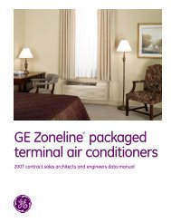
Architects and Engineers Data Manual - GE Appliances
Architects and Engineers Data Manual - GE Appliances
Architects and Engineers Data Manual - GE Appliances

Create successful ePaper yourself
Turn your PDF publications into a flip-book with our unique Google optimized e-Paper software.
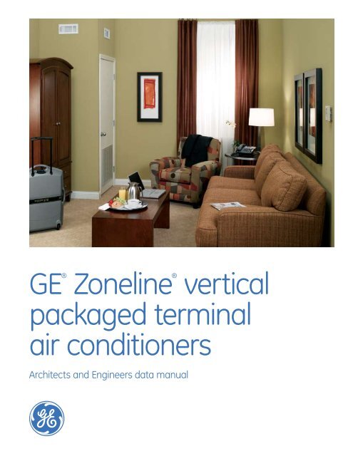
<strong>GE</strong>®<br />
Zoneline® vertical<br />
packaged terminal<br />
air conditioners<br />
<strong>Architects</strong> <strong>and</strong> <strong>Engineers</strong> data manual
Specifications<br />
Electric resistance heat<br />
Heat pumps<br />
230/208 Volt Models AZ75E09DAC AZ75E12DAC AZ75E18DAC AZ75H09DAC AZ75H12DAC AZ75H18DAC<br />
Features<br />
BTUH 9,500/9,300 11,700/11,500 17,500/17,200 9,500/9,300 11,700/11,500 17,500/17,200<br />
E.E.R. (BTUH/Watt) 10.5/10.5 10.7/10.7 10.0/10.0 10.5/10.5 10.7/10.7 10.0/10.0<br />
Dehumidification (pints/hr.) 2.7 3.6 5.0 2.7 3.6 5.0<br />
Universal Heater (kW) 2.55/3.45/5.0 2.55/3.45/5.0 2.55/3.45/5.0 2.55/3.45/5.0 2.55/3.45/5.0 2.55/3.45/5.0<br />
Heating Cap (BTUH) 8,400/8,200 10,900/10,700 15,700/15,500<br />
COP @ 47° 3.6 3.3/3.3 3.1<br />
Voltage (V) 230/208 230/208 230/208 230/208 230/208 230/208<br />
Unit Width (in.) 23-1/8 23-1/8 23-1/8 23-1/8 23-1/8 23-1/8<br />
Unit Depth (in.) 23-1/8 23-1/8 23-1/8 23-1/8 23-1/8 23-1/8<br />
Unit Height (in.) 32-1/4 32-1/4 32-1/4 32-1/4 32-1/4 32-1/4<br />
Indoor CFM (Hi/Lo) 0" ESP 310/260 375/315 550/475 310/260 375/315 550/475<br />
265/277 Volt available by special order.<br />
265/277 Volt specifications similar to 230 Volt.<br />
AZ75E09EAC AZ75E12EAC AZ75E18EAC AZ75H09EAC AZ75H12EAC AZ75H18EAC<br />
265 Volt Models Electric resistance heat Heat pumps<br />
Features<br />
BTUH 9,500 11,700 17,500 9,500 11,700 17,500<br />
Watts 950 1095 1750 950 1095 1750/1720<br />
E.E.R. 10.0 10.7 10.0 10.0 10.7 10.0/10.0<br />
Cool Amps 3.7 4.7 7.2 3.7 4.7 7.2<br />
Dehumidification<br />
(pints/hr.) 2.7 3.6 5.0 2.7 3.6 5.0<br />
SHR .70 .67 .71 .70 .67 .71<br />
Reverse Cycle (BTUH) 8,400 10,900 15,700<br />
COP @ 47° 3.6 3.3 2.5<br />
Indoor CFM (Hi/Med/Lo) 310/260/230 375/315/250 550/475/440 310/260/230 375/315/250 550/475/440<br />
Ship Wt. 152 165 174 152 165 174<br />
Net Wt. 141 154 163 141 154 163<br />
265/277 Volt available by special order.<br />
Zoneline ® Vertical Unit Nomenclature<br />
The Zoneline vertical unit is identified by a model number defining the type of unit, cooling capacity, <strong>and</strong> electrical information.<br />
When specifying or ordering the Zoneline Vertical unit the use of this nomenclature will assure receiving the correct unit.<br />
EXAMPLE<br />
A Z 7 5 E 0 9 D A C<br />
Zoneline ®<br />
packaged<br />
terminal unit<br />
Chassis series<br />
75=vertical<br />
Unit type<br />
E=cooling with electric<br />
resistance heat<br />
H=heat pump with electric<br />
resistance heat<br />
Nominal cooling capacity<br />
09=9,500 BTUH cooling<br />
12=11,700 BTUH cooling<br />
18=17,500 BTUH cooling<br />
Voltage/Phase/Frequency<br />
D=230/208 Volt, single phase, 60 Hz<br />
E=265 Volt, single phase, 60 Hz<br />
Heater<br />
configuration<br />
A=Universal heater<br />
See power<br />
connection kits<br />
section<br />
Special Features<br />
C=corrosion protection<br />
Other components are necessary for a complete<br />
installation - see System Essential Components section.<br />
Listed by<br />
Underwriters'<br />
Laboratories.<br />
MANUFA<br />
LYING WITH
Table of Contents<br />
ge.com<br />
Front Cover 1<br />
Mini-Specs/Nomenclature<br />
<br />
Table of Contents 3<br />
Introduction 4<br />
<strong>GE</strong> Zoneline ® Vertical Packaged Terminal Unit 5<br />
Features <strong>and</strong> Benefits 6-9<br />
System Essential Components 10-12<br />
Accessory List/Unit Specifications 13<br />
Air Flow Table/Dip Switches/Terminal Block - Line Art 14<br />
Required Accessories Line Art/Exp<strong>and</strong>ed View 15<br />
Utility Closet <strong>and</strong> Dimensions 16<br />
Suggested Bid Form Specifications 17<br />
Additional Specifications 18<br />
Warranty 19<br />
Important Notice<br />
Equipment used as a primary source for<br />
heating or cooling is an integral part of<br />
the building in which it is installed. Proper<br />
application is essential for satisfactory<br />
performance over a wide range of<br />
operating conditions. It is strongly<br />
recommended that a professional<br />
engineer determine proper application.<br />
If this unit is a replacement unit,<br />
its specifications <strong>and</strong> performance<br />
may differ from those of the unit it is<br />
replacing. For that reason, we again<br />
strongly recommend that a professional<br />
engineer determine proper application.
Introduction<br />
Today, guests in lodging properties, assisted living facilities <strong>and</strong> apartments desire rooms with a more home-like appearance.<br />
They expect the comforts they are accustomed to, whether they spend one night or many years. Toward that end, many lodging<br />
properties provide refrigerators, microwave ovens <strong>and</strong> remote control televisions. Many assisted living facilities provide full-size<br />
kitchen appliances in each individual apartment. All of these improvements are an attempt to improve the comfort<br />
<strong>and</strong> satisfaction of the occupant by providing a more home-like environment.<br />
Upgrading the air conditioning <strong>and</strong> heating provides another opportunity to enhance guest comfort. Years ago, an acceptable<br />
means of creating a comfortable environment was to install a window air conditioner <strong>and</strong> an electric heater mounted on the<br />
wall. The <strong>GE</strong> Zoneline ® was the first packaged terminal air conditioner introduced to the market, <strong>and</strong> it led the way in improving<br />
comfort <strong>and</strong> efficiency. And they are still used extensively as an alternative to large, expensive central systems.<br />
However, there are some inherent issues with packaged terminal units. First, since all of the components are contained in the<br />
chassis, the compressor <strong>and</strong> fan sounds can be heard in the room. In addition, since the units are usually mounted under the<br />
window there are limitations to furniture placement <strong>and</strong> curtains cannot hang to the floor. Finally, some people find the controls<br />
difficult to adjust for the desired temperature.<br />
The Vertical Packaged Terminal Air Conditioner<br />
To address these issues, <strong>GE</strong> has introduced the Vertical<br />
Zoneline. It is still a through-the-wall, packaged terminal unit,<br />
but instead of being 42" wide <strong>and</strong> installed in the middle of<br />
the room, it has a vertical configuration <strong>and</strong> is installed in a<br />
closet-like corner enclosure. The <strong>GE</strong> Zoneline Vertical Packaged<br />
Terminal Air Conditioner (ZVAC) is approximately 24" x 24" <strong>and</strong><br />
has a top air discharge that is ducted into a single room or<br />
multiple rooms. It is controlled by a wall-mounted thermostat<br />
similar to those found in most homes.<br />
Because the new ZVAC is installed in a closet, it provides<br />
a more home-like appearance to the room as well as quieter<br />
operation. And guests prefer the wall thermostat because<br />
it provides more precise settings. Since the vertical Zoneline<br />
is not installed under a window in the middle of the room,<br />
curtains can hang all the way to the floor, <strong>and</strong> more versatile<br />
room designs are possible. Because the unit is ducted, it can<br />
serve a single room or multiple rooms.<br />
The <strong>GE</strong> Zoneline Vertical Packaged Terminal Air Conditioner<br />
is a great option to st<strong>and</strong>ard PTACs for cooling <strong>and</strong> heating<br />
a variety of rooms. It provides the costs benefit of packaged<br />
terminal units with the aesthetics, quieter operation <strong>and</strong><br />
flexibility of a central system.
The <strong>GE</strong> Zoneline ® Vertical Packaged Terminal Air Conditioner<br />
ge.com<br />
The <strong>GE</strong> Zoneline ® vertical air conditioner is available in 9,500 BTUH, 11,700 BTUH or 17,500 BTUH cooling capacity with either<br />
resistance heat or heat pump units with resistance heat backup. Each cooling capacity is available in a dual rated unit that<br />
operates on either 230 volts or 208 volts <strong>and</strong> in a unit designed to operate on 265 (277) volts. All units are equipped with a<br />
3-element universal heater that provides 2.55 kW or 3.45 kW or 5.0 kW when connected with the appropriate 9-pin power<br />
connection kit to 230-volt or 265-(277) volt power. The dual rated 230/208-volt unit will produce 2.09 kW or 2.82 kW or<br />
4.09 kW when connected to 208-volt power. See page 12 for information on the power connection kits.<br />
System Features<br />
The ZVAC has a number of features that help distinguish<br />
it as the leader in the vertical unit industry. Each feature is<br />
discussed in detail in the Features <strong>and</strong> Benefits section.<br />
• Excellent efficiency <strong>and</strong> dehumidification<br />
• Unique sleeve design for easier installation <strong>and</strong> service<br />
• Three-way slide-out chassis service/maintenance flexibility<br />
• Electronic Temperature Limiting (requires room air<br />
temperature sensor accessory - RAVRMS)<br />
• Freeze Sentinel (requires room air temperature sensor<br />
accessory - RAVRMS)<br />
• Constant ON fan (required in nursing homes in some states)<br />
• Permanently Lubricated Fan Motors<br />
• St<strong>and</strong>ard Size Air Filter<br />
• Central Desk Control Capability<br />
• Occupancy Sensor Interface<br />
• HI <strong>and</strong> LOW fan speeds controlled by remote thermostat<br />
• 3-Speed Indoor Fan Motor for selectable HI <strong>and</strong> LOW speeds<br />
• Corrosion Protection Treatment St<strong>and</strong>ard<br />
• Slinger Ring Condensate Removal<br />
• Indoor Frost Control<br />
• Automatic Compressor R<strong>and</strong>om Restart<br />
• Compressor Restart Delay<br />
• Quick Heat Recovery (On Heat Pump Units)<br />
• Extended Heat Pump Operation<br />
• Reverse Cycle Heat Pump Defrost<br />
• Warranty (including both parts <strong>and</strong> labor)<br />
System Essential Components<br />
• Installation Platform<br />
• Wall Plenum<br />
• Exterior Grille<br />
• Chassis<br />
• Case<br />
• Power Connection Kit<br />
• Remote Thermostat<br />
• Filter<br />
• Return Air Grille<br />
• Ductwork<br />
• Supply Register
Features <strong>and</strong> Benefits<br />
Excellent efficiency <strong>and</strong> dehumidification<br />
<strong>GE</strong> recognizes the importance of energy efficiency <strong>and</strong><br />
dehumidification in an air conditioning system. The ZVAC<br />
unit is rated in accordance with ARI (Air Conditioning <strong>and</strong><br />
Refrigerating Institute) St<strong>and</strong>ard 310/380-93 which uses<br />
EER (Energy Efficiency Rating) as a means of reporting the<br />
relative cooling efficiency of the unit.<br />
EER is the rating system used for Packaged Terminal Air<br />
Conditioners <strong>and</strong> Heat Pumps.<br />
The <strong>GE</strong> Zoneline ® Vertical Packaged Terminal Heat Pump has<br />
outst<strong>and</strong>ing COP ratings. The measurement of the efficiency<br />
of the heat pump output, when compared to electric resistance<br />
heat, is called the Coefficient of Performance (COP). This<br />
number provides a basis not only for comparing the heat<br />
pump output to electric resistance heat, but also the ability<br />
to directly compare heat pumps with the same range of<br />
capacity to one another.<br />
Unique Sleeve Design<br />
The ZVAC case is installed on a field supplied platform <strong>and</strong><br />
attached to the wall plenum with screws to support platform<br />
with field supplied screws. See page 10 for platform<br />
construction details.<br />
The chassis slides into the sleeve, allowing for easy removal<br />
of the unit for servicing <strong>and</strong> cleaning without the need to<br />
remove condensate lines.<br />
Three-Way Slide-Out Chassis<br />
The case is designed to allow the installation of the chassis<br />
from the front or either side of the case. This provides greater<br />
flexibility in building <strong>and</strong> room design <strong>and</strong> unit placement. If<br />
access to the front of the unit is restricted by a wall or furniture<br />
placement, the chassis can slide in from either side of the case.<br />
If an alcove or offset is designed into the building facade,<br />
the three-way slide-out chassis enables the unit to be easily<br />
installed <strong>and</strong> removed for service.<br />
Electronic Temperature Limiting<br />
Although the vertical unit is controlled by a wall mounted<br />
thermostat, there may be a need to prevent the temperature<br />
from being set to extreme energy wasting settings. The ZVAC unit<br />
has seven independent programmable heating <strong>and</strong> cooling<br />
temperature limits. A wide selection of limits eliminates the<br />
need to reset the limits seasonally. The Temperature Limiting<br />
feature requires the use of the optional room air temperature<br />
sensor, model RAVRMS. Designed to be mounted on the wall<br />
of the unit enclosure closet, the Room Air Temperature Sensor<br />
allows any compatible thermostat to be used with the unit <strong>and</strong><br />
provide Temperature Limiting.<br />
The limits are set by dip switches located on the ZVAC unit <strong>and</strong><br />
are not accessible by the room occupant. Location of the dip<br />
switches <strong>and</strong> the temperature settings are shown on page 14.<br />
Cooling Temperature Limits degrees F.<br />
Min 60 o 64 o 66 o 68 o 70 o 72 o 74 o 76 o<br />
Max 85 o 85 o 85 o 85 o 85 o 85 o 85 o 85 o<br />
Heating Temperature Limits degrees F.<br />
Min 60 o 60 o 60 o 60 o 60 o 60 o 60 o 60 o<br />
Max 85 o 80 o 78 o 76 o 74 o 72 o 70 o 65 o<br />
Freeze Sentinel <br />
To prevent damage to plumbing <strong>and</strong> room furnishings by<br />
freezing temperatures, the ZVAC unit can provide Freeze<br />
Sentinel which turns the resistance heaters on at 41 o F.,<br />
warms the indoor air to 46 o F., <strong>and</strong> shuts the heater off.<br />
The Freeze Sentinel feature requires the use of the optional<br />
Room Air Temperature Sensor, model RAVRMS.<br />
Designed to be mounted on the wall of the unit enclosure<br />
closet, the Room Air Temperature Sensor allows any<br />
compatible thermostat to be used with the unit <strong>and</strong><br />
provide Freeze Sentinel protection. The Freeze Sentinel<br />
protection is automatic with the installation of the RAVRMS.<br />
Even if the unit is connected to a Central Desk Control system<br />
or a Room Occupancy Sensor system, <strong>and</strong> the unit is turned<br />
off by the controlling system, Freeze Sentinel is still active to<br />
provide protection. It may be defeated by switching the unit’s<br />
ON/OFF switch to the OFF position, removing the power supply<br />
to the unit or putting #2 dip switch in up position.<br />
Constant ON fan<br />
Some localities may require the indoor fan on Packaged<br />
Terminal Air Conditioners to operate at all times, even when<br />
the wall primary control would normally turn the unit off. To<br />
accommodate this requirement <strong>and</strong> provide the feature for<br />
use by anyone wanting to operate the unit in this manner,<br />
<strong>GE</strong> has provided a switch on the ZVAC that will allow this<br />
mode of fan operation.<br />
If the controlling dip switch is set in the UP setting, the fan<br />
will run unless the unit’s ON/OFF switch is set to the OFF<br />
position or power is removed from the unit.
Features <strong>and</strong> Benefits<br />
Permanently Lubricated Fan Motors<br />
The ZVAC has two permanently lubricated, totally enclosed<br />
fan motors. The motors are permanently lubricated to reduce<br />
maintenance <strong>and</strong> totally enclosed to keep dirt <strong>and</strong> water out<br />
of the motor windings.<br />
St<strong>and</strong>ard Size Air Filter<br />
A number of filters, providing varying degrees of filtering<br />
efficiency are available on the market today. <strong>GE</strong> has designed<br />
the ZVAC to accommodate a number of filter placement<br />
options. All of the options designed for the unit use a st<strong>and</strong>ard<br />
size 20" x 20" x 1" filter. Since the filter is field supplied, <strong>GE</strong> has<br />
allowed the owner or property manager to decide which type<br />
of filter to use with the unit.<br />
A different size filter may also be used in a field supplied frame<br />
installed in a return air grille mounted in the closet enclosure<br />
door or wall. If a different size filter is used, it must be at least<br />
20" x 20" x 1" <strong>and</strong> provide no more restriction to air flow than<br />
the st<strong>and</strong>ard 20" x 20" x 1" filter.<br />
The unit must not be operated without a filter in<br />
place, even during construction.<br />
<strong>GE</strong> provides three filter placement options for design <strong>and</strong><br />
installation flexibility. A filter bracket is provided in the front<br />
panel of the ZVAC case, which allows the use of a louvered<br />
closet door. The bracket is mounted to allow the filter to be<br />
inserted from the top of the bracket rather than sliding in<br />
from the side, where the enclosure wall may interfere with<br />
filter removal.<br />
An access panel, accessory model number RAVRG1, for the<br />
closet enclosure is the second filter placement option. The<br />
access panel requires a 28 1/4" wide by 48 1/4" high cutout<br />
in the unit closet enclosure wall <strong>and</strong> provides access to the<br />
unit for servicing <strong>and</strong> removal. The bottom of the access panel<br />
should be at least 1" below the unit support platform to allow<br />
for easy removal of the ZVAC unit.<br />
The third filter placement option provided by <strong>GE</strong> is incorporated<br />
in a return air grille, accessory model number RAVRG2,<br />
designed to be mounted in a flat closet access door. The<br />
door must have a minimum clear opening of 24" to allow for<br />
installation <strong>and</strong> removal of the unit. <strong>GE</strong> recommends a 28"<br />
wide door. A 20 3/8" wide by 20 3/8" high cutout is required in<br />
the door to accommodate the grille <strong>and</strong> filter bracket.<br />
Only one filter is to be used in the installation. Multiple filters<br />
will reduce the air flow <strong>and</strong> affect unit performance. A clean<br />
filter is essential to efficient unit operation. The filter should<br />
be checked at least every 30 days <strong>and</strong> replaced if dirty.<br />
Central Desk Control<br />
ge.com<br />
Terminals are provided on the unit to allow a Central Desk<br />
Control system to be interfaced with the unit. The most common<br />
installation of this type of system is a switch mounted at the<br />
registration desk; <strong>and</strong>, upon guest check-in, a switch is activated<br />
to allow the air conditioner to operate.<br />
Likewise, when the guest checks out, the device is switched<br />
to the “OFF” setting so the unit will not operate when the room<br />
is not rented. In some resort areas, devices are connected to<br />
sliding glass doors, <strong>and</strong> opening the doors causes a contact to<br />
close, turning the air conditioner off. This prevents the unit from<br />
running <strong>and</strong> wasting energy with the sliding glass open.<br />
Important CDC Notes:<br />
1) The unit requires the use of a normally open switch.<br />
Closing the circuit interrupts power to the unit.<br />
2) Both wires comprising the circuit must connect to the<br />
CDC terminals on the unit <strong>and</strong> to the controlling switch.<br />
Do not use a common buss (at the unit or at the switch<br />
panel) in the wiring.<br />
3) A 24-volt transformer is contained within the ZVAC unit.<br />
No external voltage may be applied to the unit through<br />
the CDC terminals.<br />
4) Minimum wire size for CDC wiring:<br />
Wire Size # AWG Maximum Allowable Length<br />
#22 600 Ft.<br />
#20 900 Ft.<br />
#18 1500 Ft.<br />
#16 000 Ft.<br />
Occupancy Sensor Interface<br />
The ZVAC is equipped with a terminal connection to allow it<br />
to interface with a motion sensor <strong>and</strong> a door sensor to allow<br />
a room occupancy detection system to be connected to the<br />
unit. Various companies market <strong>and</strong> install room occupancy<br />
systems as a means of reducing the operating cost of<br />
the unit. <strong>GE</strong> does not market or install these systems but<br />
provides the interface terminals on the unit <strong>and</strong> logic within<br />
the microprocessor controls to permit these systems to be<br />
installed at a minimum cost to the property owner.<br />
HIGH <strong>and</strong> LOW Fan Speeds<br />
If the ZVAC is connected to a wall thermostat without the ability<br />
to provide two fan speeds, the fan speed will be determined by<br />
connecting the wire controlling the fan to either the Low Speed<br />
Fan terminal or the High Speed Fan terminal on the unit.
Features <strong>and</strong> Benefits<br />
3-Speed Indoor Fan Motor<br />
for selectable HIGH <strong>and</strong> LOW speeds<br />
Since the ZVAC discharge air may be routed through duct<br />
work for air distribution into the room <strong>and</strong> into other rooms,<br />
the units are equipped with a 3-speed fan to provide greater<br />
air movement, to compensate for the additional duct length.<br />
<strong>GE</strong> recommends an HVAC engineer be consulted to determine<br />
the best fan speed for the application.<br />
A switch on the unit allows the selection of the medium fan<br />
speed to be used as either LOW speed, in which case the<br />
high fan speed becomes HIGH, or the medium speed may<br />
be designated as the HIGH speed, in which case the low fan<br />
speed is utilized as LOW.<br />
For example, on the nominal 9500 BTUH unit, the three fan<br />
speeds provide either 275 CFM on the lowest fan speed, 300<br />
CFM on the medium fan speed, <strong>and</strong> 325 CFM on the highest<br />
fan speed.<br />
Selecting the medium speed as the high speed setting would<br />
provide 275 CFM on LOW speed <strong>and</strong> 300 CFM on HIGH speed.<br />
Selecting the medium speed as the low speed setting would<br />
provide 300 CFM on LOW speed <strong>and</strong> 325 CFM on HIGH speed.<br />
Higher CFMs tend to increase the operating sound level, both<br />
from fan noise <strong>and</strong> from the air noise in the duct. Higher CFMs<br />
also reduce the dehumidification rate of the unit, while lower<br />
CFMs provide quieter operation <strong>and</strong> better dehumidification.<br />
However, if the CFMs are not high enough to adequately move<br />
the air through the duct system, the unit will not be able to<br />
provide a comfortable room.<br />
Corrosion Protection Treatment (St<strong>and</strong>ard)<br />
All ZVAC units are protected<br />
against damage from seacoast<br />
area corrosion. Components<br />
that are in contact with the<br />
salt air have special coatings<br />
or are made of non-corroding<br />
materials to help withst<strong>and</strong><br />
the corrosive effects of the<br />
environment. This protection<br />
includes the use of totally<br />
enclosed fan motors with<br />
painted casings, a special<br />
coating on the outdoor coil, use of stainless steel screws <strong>and</strong><br />
brackets, <strong>and</strong> additional paint on components like the base pan.<br />
Slinger Ring Condensate Removal<br />
Condensate water removed from the indoor air is dispersed<br />
into the air stream by the outdoor fan slinger ring <strong>and</strong><br />
deposited on the hot outdoor coil. The water helps cool the<br />
refrigerant in the outdoor coil <strong>and</strong> increases the efficiency of<br />
the air conditioner.<br />
<br />
Indoor Coil Frost Control<br />
Under certain operating conditions, frost can form on the indoor<br />
coil of an air conditioner, reducing air flow, <strong>and</strong> causing a lack<br />
of cooling complaint. In order to prevent frost from forming, the<br />
ZVAC has an automatic frost control on the indoor coil. When<br />
frost begins to form on the coil, the compressor stops until the<br />
coil temperature increases <strong>and</strong> the frost dissipates.<br />
At this time, the compressor resumes operation <strong>and</strong> cooling<br />
continues. The indoor fan remains running during the time<br />
the compressor is off to help warm the coil with room<br />
temperature air.<br />
Automatic Compressor R<strong>and</strong>om Restart<br />
In the event of a power interruption, all compressors<br />
attempting to restart immediately when power is restored<br />
can result in a power surge that can cause another power<br />
failure. The microprocessor in the ZVAC unit has a r<strong>and</strong>om<br />
restart logic system that prevents all compressors from<br />
restarting at the same instant.<br />
Compressor Restart Delay<br />
ZVAC units are designed to provide a minimum of three<br />
minutes of compressor off time to allow refrigerant pressures<br />
to equalize before attempting to restart. Attempting to restart<br />
against a high head pressure shortens compressor <strong>and</strong><br />
overload protector life.<br />
The units are also designed to provide a minimum of three<br />
minutes of compressor run time to prevent short cycling from<br />
disturbing the room occupant.<br />
Quick Heat Recovery (On Heat Pump Units)<br />
Heat pumps save money compared to electric resistance<br />
heat, but if the unit cannot provide room occupant comfort,<br />
the savings may be of questionable benefit. <strong>GE</strong> has years of<br />
experience with designing Zoneline heat pumps to solve the<br />
problem of guest complaints.<br />
The heat pump unit incorporates a two-stage heat/one-stage<br />
cooling thermostat that utilizes the resistance heat to bring the<br />
room temperature to within 2 o F. of the thermostat set point<br />
before initiating heat pump operation. This method addresses<br />
the two major complaints about heat pump operation: taking<br />
too long to warm the room <strong>and</strong> low discharge air temperature.<br />
Full electric resistance heat is utilized when the unit is first<br />
turned on or when the unit is operating in heat pump mode<br />
<strong>and</strong> the temperature in the room falls more than 2 o F. below<br />
the thermostat set point.<br />
Extended Heat Pump<br />
Operation/Reverse Cycle Defrost<br />
Heat exists in the outdoor air at temperatures even below 0 o F.<br />
Many central systems, with larger outdoor coils, operate in<br />
the heat pump mode down to temperatures in the mid-teens<br />
or even to single-digit temperatures. Central systems are able
Features <strong>and</strong> Benefits<br />
to operate this low because of the larger outdoor coil area<br />
<strong>and</strong> because central system heat pumps have a reverse cycle<br />
defrost mode that melts accumulated frost off the outdoor coil.<br />
Typical vertical packaged terminal heat pump units terminate<br />
heat pump operation <strong>and</strong> switch to more expensive resistance<br />
heat at outdoor temperatures in the 40 o F. to 45 o F. range. They<br />
must terminate heat pump operation before a frost build-up<br />
occurs on the outdoor coil since they have no way of eliminating<br />
the frost.<br />
<strong>GE</strong> offers a reverse cycle defrost system, like the central systems,<br />
on all new Zoneline Packaged Terminal Heat Pumps. This<br />
provides the owners with the savings realized by the ability to<br />
operate in heat pump mode to lower outdoor temperatures. <strong>GE</strong><br />
has adapted the reverse cycle heat pump defrost system to the<br />
ZVAC for greater savings in heat pump mode.<br />
The ZVAC will provide heat pump savings down to a 25°F.<br />
outdoor temperature. At temperatures below 25°F., the unit<br />
will automatically switch to electric heat. When the outdoor<br />
temperature rises to 32°F., the unit will automatically switch<br />
back to heat pump operation. As long as the heat pump output<br />
is able to maintain the room temperature within 2 o F. of the<br />
thermostat set point, the unit will run in heat pump mode down<br />
to 25 o F. outdoor air temperature. The resistance heater <strong>and</strong> the<br />
heat pump do not operate simultaneously.<br />
If the outdoor temperature is above 25 o F. <strong>and</strong> if the room<br />
temperature falls more than 2 o F. below the set point, the<br />
thermostat automatically switches the unit to resistance heat.<br />
If frost develops on the outdoor coil at temperatures above 25 o F.,<br />
the unit initiates the reverse cycle defrost operation to warm the<br />
outdoor coil <strong>and</strong> allow the unit to resume heat pump operation.<br />
Prior to initiating the defrost sequence, the electric heaters will<br />
be energized to bring the room to the thermostat set point.<br />
Immediately after the defrost is completed, the electric heaters<br />
are energized to bring the room back to room temperature. The<br />
defrost sequence is terminated when the outdoor coil reaches<br />
68°F. or when nine minutes has elapsed.<br />
Concealed <strong>Manual</strong> Vent Control<br />
Open ventilation doors on <strong>GE</strong> Vertical Zoneline ® Packaged<br />
Terminal Air Conditioners <strong>and</strong> Heat Pumps allow outside air to<br />
enter the room through a screen-covered opening in the weather<br />
barrier that separates the indoor <strong>and</strong> outdoor sections of the<br />
unit. For each cfm of air to enter the room, an equal amount of<br />
air must be removed through exhaust fans in the bathroom or<br />
roof tops. Outside ambient air entering the room through this<br />
screened vent opening is not conditioned. This unconditioned<br />
air becomes mixed with the conditioned air that is circulated<br />
by the ZVAC indoor fan. This air mixture generates an additional<br />
heat load/heat loss that causes the unit to run longer <strong>and</strong> may<br />
translate into higher operating costs.<br />
A concealed lever located behind the front cover of the ZVAC<br />
is used to open <strong>and</strong> close the vent door. Zoneline vent openings<br />
are not intended to be the source of make-up air for building<br />
ventilation systems due to the additional heating or cooling<br />
loads generated.<br />
Ventilation CFM at various ESP points:<br />
Warranty (including both parts <strong>and</strong> labor)<br />
ge.com<br />
Ventilation (CFM)<br />
static pressure 9000btu 12000btu 18000btu<br />
inch water 208V 230V 208V 230V 208V 230V<br />
0.0 62 66 66 70 79 83<br />
0.1 55 59 56 58 77 79<br />
0.2 49 50 50 52 76 76<br />
0.3 46 48 44 46 70 72<br />
0.4 35 38 36 40 63 64<br />
<strong>GE</strong> has provided the most comprehensive warranty available,<br />
without additional charge, on a vertical packaged terminal unit.<br />
The entire warranty covering the ZVAC unit is printed in the back<br />
of this manual but the highlights are:<br />
• Limited One-Year Warranty - covering any part that fails<br />
as a result of a defect in materials or workmanship - parts,<br />
labor, <strong>and</strong> on-site service free of charge.<br />
• Limited Additional Four-Year Warranty - covering any part<br />
of the sealed refrigerating system (Compressor, condenser,<br />
evaporator, <strong>and</strong> all connecting tubing) that fails due to<br />
a defect in materials or workmanship - parts, labor, <strong>and</strong><br />
on-site service free of charge.<br />
• Limited Parts Warranty for 2nd - 5th Year - covering fan<br />
motors, switches, heater, heater protectors, compressor<br />
overload, solenoids, circuit boards, auxiliary controls,<br />
thermistors, frost controls, capacitors <strong>and</strong> resistors. This<br />
is a limited warranty <strong>and</strong> does not include labor or cartage.<br />
System Essential Components<br />
<strong>and</strong> Installation<br />
Each Zoneline Vertical Packaged Terminal Air Conditioner<br />
or heat pump requires an installation platform, wall plenum,<br />
exterior grille, chassis including case, power connection kit,<br />
remote thermostat, filter <strong>and</strong> a return air grille, ductwork<br />
<strong>and</strong> supply registers.<br />
The installation platform, ductwork <strong>and</strong> supply registers are field<br />
supplied. Each of the other components is ordered separately.<br />
The wall plenum, exterior grille <strong>and</strong> power connection kit are<br />
specifically designed to interface with the <strong>GE</strong> ZVAC unit <strong>and</strong><br />
must be purchased from the same source as the unit.<br />
The remote thermostat <strong>and</strong> the return air grille are offered as<br />
accessories by <strong>GE</strong>, but may be purchased from a source other<br />
than <strong>GE</strong>. If a non-<strong>GE</strong> thermostat or return air grille is used, they<br />
must have the minimum requirements to work properly with<br />
the unit. The filter is a st<strong>and</strong>ard 20" x 20" x 1" filter available<br />
where air conditioner filters are sold. The room temperature<br />
sensor is an optional <strong>GE</strong> accessory available from the same<br />
source as the unit.
System Essential Components <strong>and</strong> Installation<br />
Wall Plenum<br />
Since the unit itself does not install in<br />
the wall opening, the use of a plenum is<br />
necessary to contain <strong>and</strong> separate the<br />
outdoor air paths. The plenum must be<br />
able to hold water in the bottom without<br />
leaking into the wall cavity. It also must<br />
have a “splitter” to separate the outdoor<br />
air paths <strong>and</strong> prevent the discharge air<br />
from being drawn back into the unit.<br />
The wall plenum is the first component<br />
to be installed. The wall opening location<br />
for the plenum needs to extend 1" below<br />
the top of the Installation Platform. Since the platform must be<br />
a minimum of 8" off the floor, the cutout for the plenum must<br />
be a minimum of 7" plus the thickness of the platform base,<br />
off the interior finished floor. <strong>GE</strong> offers four plenums, <strong>and</strong> the<br />
choice of the correct plenum is determined by the thickness of<br />
the building exterior wall. Each of the plenums is 19 3/4" wide<br />
by 32" high <strong>and</strong> require a 20" wide by 32 1/4" high cutout in<br />
the wall.<br />
The plenum is to be installed square <strong>and</strong> level in the opening<br />
<strong>and</strong> secured to the wall construction with screws or nails in the<br />
sides located a minimum of 2" from the bottom of the plenum.<br />
No nails or screws may be used in the bottom or top of the<br />
plenum to ensure against water entering the wall cavity.<br />
The plenum is not load bearing, so a proper header needs to<br />
be installed above the plenum the same as over any window<br />
opening in the wall. If the building construction is brick,<br />
concrete block, or other non self-supporting material, a lintel<br />
must be installed over the plenum opening. The plenum must<br />
be caulked to the wall, both to the outdoor wall face <strong>and</strong> to<br />
the interior wall, along all four sides to prevent air <strong>and</strong> water<br />
infiltration. The installation of flashing, with a 45 o drip lip, is<br />
recommended under the plenum.<br />
Wall plenum models:<br />
RAVWP6 - For installations with walls up to 6" thick<br />
RAVWP8 - For installations with walls up to 8" thick<br />
RAVWP12 - For installations with walls up to 12" thick<br />
RAVWP15 - For installations with walls up to 15" thick<br />
Installation Platform<br />
The ZVAC requires<br />
a field supplied<br />
installation<br />
platform. The<br />
installation<br />
platform must be<br />
a minimum of 23<br />
1/4" square, with<br />
legs to raise the platform a minimum of 8" (12" recommended),<br />
<strong>and</strong> have a minimum load bearing capacity of 175 pounds.<br />
The platform legs must be positioned so access to the unit<br />
drain connection is not blocked. The centerline of the unit drain<br />
connection is located 5 1/4" from the left side of the unit <strong>and</strong><br />
8 1/2" from the left rear corner of the unit. A square cutout,<br />
3" by 3", should be made in the platform centered 5 5/8" from<br />
the left edge <strong>and</strong> 8 5/8" from the edge of the platform that will<br />
be installed against the plenum.<br />
The closet enclosure needs to be large enough to provide the<br />
following clearances for the platform (assuming the minimum<br />
23 1/4" square platform):<br />
Unit installed from the front of the case - 4" minimum clearance<br />
from front of platform to inside of closet door - 3" minimum<br />
clearance on each side. Unit installed from the side of the case<br />
- 5" minimum clearance from the installation side wall or door<br />
- 4" minimum in the front of the unit - 3" minimum on the side<br />
opposite the installation side.<br />
When determining the closet depth, consideration must be<br />
given to the fact that the plenum may protrude into the closet<br />
if the plenum is thicker than the exterior wall.<br />
The platform is positioned against the plenum, with the plenum<br />
centered on the edge of the platform, <strong>and</strong> secured to the floor<br />
with brackets <strong>and</strong> screws. The platform needs to be secured to<br />
the floor to prevent the platform from shifting since the unit is<br />
secured to both the plenum <strong>and</strong> the mounting platform.<br />
Closet Sizing Guide<br />
Since the most critical aspect of installing a <strong>GE</strong> Vertical<br />
PTAC/PTHP is the closet size, here are a few hints to prevent<br />
installation, application, <strong>and</strong> operational problems.<br />
Minimum Inside Closet Width Minimum Inside Closet Depth<br />
“C” dimension........................3" ‘A’ dimension..........................?"<br />
“D” dimension........................3" ‘B’ dimension..........................?"<br />
ZVAC dimension.......23 1/8" ZVAC dimension.......23 1/8"<br />
Total.............29 1/8"<br />
Total...........................?<br />
Outside Wall<br />
Closet Wall<br />
C<br />
Outdoor Grille<br />
23 1/8”<br />
Wide<br />
ZVAC Chassis/Case<br />
23 1/8”<br />
Deep<br />
E<br />
B<br />
Plenum<br />
Important Notes<br />
‘A’ dimension determined by wall thickness <strong>and</strong> plenum<br />
size selected<br />
‘B’ dimension minimum 4" for front installation<br />
‘B’ dimension minimum 5" for side installation<br />
‘E’ dimension minimum for 28" door - 33"<br />
‘E’ dimension minimum for RAVRG1 Access Panel - 30"<br />
NOTE: For easier installation <strong>and</strong> removal, door or access panel should be<br />
centered on Zoneline.<br />
A<br />
D<br />
E<br />
10
System Essential Components <strong>and</strong> Installation<br />
ge.com<br />
Exterior Grille<br />
The architectural louver exterior grille<br />
is mounted to the exterior flange of the<br />
plenum <strong>and</strong> held in place with four screws<br />
inserted from inside enclosure closet. The<br />
grille is designed specifically for use with<br />
the ZVAC unit <strong>and</strong> the use of any other grille<br />
must be approved by <strong>GE</strong> Air Conditioning<br />
Applications Engineering.<br />
Unit including sleeve <strong>and</strong> front panel<br />
The unit is packaged with the case <strong>and</strong> the front panel in place<br />
(filter not included). Installation begins by removing the front<br />
panel <strong>and</strong> pulling the unit out of the case. The empty case is<br />
positioned on the platform in the closet with the outdoor side<br />
facing the wall plenum opening <strong>and</strong> secured to the plenum<br />
with six screws.<br />
Level the case using the four<br />
leveling legs <strong>and</strong>, using the holes<br />
in the bottom of the case as<br />
guides, drill holes in the mounting<br />
platform to secure the case to the<br />
platform. Use four field-supplied<br />
bolts, washers <strong>and</strong> nuts to<br />
secure the case to the mounting<br />
platform. Do not tighten the bolts<br />
to the point of distorting the case.<br />
Failure to secure the case to the<br />
platform may result in excessive<br />
unit vibration <strong>and</strong> increased noise level. Install the unit into the<br />
case, either through the front panel opening or remove the<br />
side panel if a side installation is to be made. With the unit in<br />
position in the case, replace the front panel <strong>and</strong>, if removed,<br />
the side panel. Ground the unit to the case by installing the<br />
front unit-to-case hex bolt <strong>and</strong>/or the case-to-unit side screw.<br />
The drain connection is made by connecting a 90 o PVC<br />
elbow to the unit’s female 3/4" NPT drain connector. The other<br />
end of the elbow is used to run the drain to either the internal<br />
or external drain.<br />
A 10" diameter flange on the top of the unit is used to connect<br />
to field supplied, insulated, flexible or rigid transition duct with<br />
an adjustable ring clamp.<br />
Flexible duct may be used for transitions only. Rigid duct must<br />
be used for 90 o bends <strong>and</strong> tees. Do not use flexible duct for<br />
unsupported runs of five feet or more.<br />
Power Connection Kit<br />
The ZVAC units have a universal heater assembly that is<br />
capable of producing electric resistance heat that can operate<br />
on a 15-amp, 20-amp, or 30-amp circuit. The amount of<br />
resistance heat is determined by the selection of the correct<br />
power connection kit. This is the same type of connection<br />
used by <strong>GE</strong> for years in the Premium series of the regular<br />
Zoneline unit.<br />
Units installed on 230 or 208-volt circuits may be line cord<br />
connected by plugging the line cord into a wall-mounted<br />
receptacle in the enclosure closet or directly connected.<br />
All ZVAC units come with a unit mounted junction box<br />
to contain the wiring connections if a direct connection<br />
installation is required. The same power connection kit is<br />
used for line cord connection or to make a direct connection.<br />
Instructions for making a direct connection on 230 or 208-volt<br />
circuits are included in the unit installation instructions.<br />
230/208 Volt Line Cord Connected Units<br />
Power Connection RAK3152 RAK3202 RAK3302<br />
Heater kW 2.55/2.09 3.45/2.82 5.0/4.09<br />
Watts 2550/2090 3450/2820 5000/4090<br />
Heater Amps 11.0/10.0 15.0/13.6 21.7/19.7<br />
Minimum Circuit 15 20 30<br />
Recommended<br />
Protective Device<br />
Plug Configuration<br />
15 Amp Time Delay<br />
Fuse or Breaker<br />
15 Amp T<strong>and</strong>em<br />
Units installed on a 265-volt circuit must be direct connected<br />
in accordance with National Electrical Code. All ZVAC units<br />
come with a unit mounted junction box to contain the wiring<br />
connections when direct connection installation is made.<br />
Return air grille, access panel or<br />
louvered closet door<br />
20 Amp Time Delay 30 Amp Time Delay<br />
Fuse or Breaker Fuse or Breaker<br />
20 Amp<br />
30 Amp<br />
Perpendicular Large T<strong>and</strong>em<br />
265 Volt Permanent Connected Units<br />
Power Connection RAK5157 RAK5207 RAK5307<br />
Heater kW 2.55 3.45 5.0<br />
Watts 2550 3450 5000<br />
Heater Amps 9.7 13.1 18.9<br />
Minimum Circuit 15 20 30<br />
Recommended<br />
Protective Device<br />
Plug Configuration<br />
15 Amp Time Delay<br />
Fuse or Breaker<br />
15 Amp T<strong>and</strong>em<br />
20 Amp Time Delay 30 Amp Time Delay<br />
Fuse or Breaker Fuse or Breaker<br />
20 Amp<br />
30 Amp<br />
Perpendicular Large T<strong>and</strong>em<br />
The return air from the room to the unit<br />
may enter the enclosure closet through<br />
one of four ways. A louvered door may be<br />
installed on the closet to allow return air to<br />
enter the closet through the louvers. When<br />
a louvered door is used, the filter would be<br />
installed in the filter bracket on the front<br />
panel of the unit.<br />
A wall-mounted access panel may be<br />
used instead of the louvered door. In this<br />
installation access to the unit is through<br />
a wall-mounted access panel rather than<br />
a door. The return air is through the panel. The access panel,<br />
model RAVRG1, requires a 28" wide by 48" high cutout in the<br />
wall <strong>and</strong> the filter bracket is behind the grille louvers.<br />
The return air grille, model RAVRG2, may also be used <strong>and</strong><br />
is designed to be installed in a 20 3/8" by 20 3/8" cutout in a<br />
flush closet door. In this installation, the filter fits in a bracket<br />
in the RAVRG2.<br />
A field-supplied return air grille, with a minimum dimension of<br />
20" by 20", may be used if mounted in a cutout in the door or<br />
wall. When employing this method for return air, the filter is<br />
installed in the bracket mounted on the unit.<br />
11
System Essential Components <strong>and</strong> Installation<br />
Remote Thermostat<br />
The ZVAC units are controlled by a wallmounted<br />
thermostat. <strong>GE</strong> offers a complete<br />
line of thermostats to interface with the<br />
units or most 24-VAC thermostats may<br />
be used. If a non-<strong>GE</strong> thermostat is used, the compatibility of the<br />
thermostat with the unit is the responsibility of the installer. The unit<br />
has an integral transformer <strong>and</strong> no external voltage or transformer<br />
may be used.<br />
Resistance Heat - Single Stage Cooling/<br />
Single Stage Heating Thermostats<br />
<strong>GE</strong> Thermostat Model Number Type Low Voltage Conductors<br />
RAK163A1 Mechanical 4<br />
RAK163D1 Mechanical 5<br />
RAK163P1 Programmable 5<br />
RAK164D1 Digital 5<br />
RAK164P1 Programmable 5<br />
Heat Pump - Single Stage Cooling/<br />
Two Stage Heating Thermostats<br />
<strong>GE</strong> Thermostat Model Number Type Low Voltage Conductors<br />
RAK147 Mechanical 6<br />
RAK147D1 Mechanical 6<br />
RAK147P1 Programmable 6<br />
RAK148P1 Programmable 6<br />
RAK148D1 Digital 6<br />
One of the customer-requested features on the ZVAC unit is the<br />
ability for the user to select either HIGH or LOW fan speed operation<br />
at the thermostat.<br />
Maximum wiring length <strong>and</strong> wire size - AWG 18 up to 66 feet - AWG<br />
20 up to 66 feet - AWG 24 up to 40 feet.<br />
St<strong>and</strong>ard Size Filter (field supplied)<br />
The ZVAC unit uses a st<strong>and</strong>ard size 20" by 20" by 1" air<br />
conditioner/furnace filter. The filter is not provided with the unit,<br />
but can be purchased at any building supply or maintenance<br />
equipment supplier. The st<strong>and</strong>ard size filter allows the use of<br />
special filters if the owner desires. Regardless of the installation <strong>and</strong><br />
the return air method, only one filter may be used in the installation.<br />
Optional: Room Air Temperature Sensor<br />
The Room Air Temperature Sensor accessory, model number<br />
RAVRMS, is available as an option to allow Temperature Limiting <strong>and</strong><br />
Freeze Sentinel protection. The Room Air Temperature Sensor has a<br />
nine-foot wiring harness designed to allow the sensor to mount on<br />
the room side of the closet wall. Terminal connectors are located on<br />
the terminal block inside the unit to permit easy connection of the<br />
Room Air Temperature Sensor conductors.<br />
installation may have different requirements for the ductwork<br />
<strong>and</strong> supply registers.<br />
Electrical Information - General<br />
Zoneline Vertical Packaged Terminal Air Conditioners are to be<br />
connected to a single-phase 60 hertz power. Units with the voltage<br />
designator “D” in the 8th character of the model number may be<br />
operated on either nominal 230-volt or 208-volt power. The units are<br />
designed to operate properly on power sources from 197 volts to<br />
253 volts. Units with the voltage designator “E” in the 8th character<br />
of the model number are to be operated on nominal 265-volt power.<br />
This unit is also used on 277-volt power. The units are designed to<br />
operate properly on power sources from 238 volts to 292 volts.<br />
For all installations, feeder, sub-feeder, branch circuit <strong>and</strong> electrical<br />
protective devices must conform to all local codes. In the absence<br />
of a local code, the National Electrical Code should be followed.<br />
Each unit should be installed on a single branch circuit. More<br />
than one unit per branch circuit is not recommended. All wiring,<br />
including installation of receptacle, must conform to local<br />
electrical regulations <strong>and</strong> codes. When in doubt, consult the<br />
National Electrical Code.<br />
Power Connection Kits are Required<br />
on Vertical Zoneline ® Chassis (See chart below.)<br />
The correct kit for the installation is determined by the voltage<br />
<strong>and</strong> amperage of the electrical circuit <strong>and</strong> the means of connecting<br />
the unit to the building wiring. If the unit is to be plugged into a<br />
receptacle, a power cord kit would be used; if the unit is to be<br />
permanently connected, a permanent connection kit would be used.<br />
Power Connection Kits<br />
Required on Premium models.<br />
See specification sheet for heater<br />
kW <strong>and</strong> branch circuit ampacity.<br />
RAK3152/3202/3302<br />
230/208 Volt Cord Connection Kit<br />
230/208 Volt Line Cord Connected Units<br />
Power Connection RAK3152 RAK3202 RAK3302<br />
Heater kW 2.55/2.09 3.45/2.82 5.0/4.09<br />
Heater Amps 11.0/10.0 15.0/13.6 21.7/19.7<br />
Minimum Circuit Amps 15 20 30<br />
Recommended<br />
Protective Device<br />
15 Amp Time Delay<br />
Fuse or Breaker<br />
20 Amp Time Delay<br />
Fuse or Breaker<br />
30 Amp Time Delay<br />
Fuse or Breaker<br />
265/277 Volt Permanent Connected Units<br />
Power Connection RAK5157 RAK5207 RAK5307<br />
Heater kW 2.55 3.45 5.0<br />
Heater Amps 9.7 13.1 18.9<br />
Minimum Circuit Amps 15 20 30<br />
Recommended<br />
Protective Device<br />
15 Amp Time Delay<br />
Fuse or Breaker<br />
20 Amp Time Delay<br />
Fuse or Breaker<br />
30 Amp Time Delay<br />
Fuse or Breaker<br />
Ductwork (field supplied)<br />
Supply Registers (field supplied)<br />
Ductwork <strong>and</strong> supply registers are mentioned here as System<br />
Essential Components, because they are necessary to complete<br />
the installation. These components are field supplied since each<br />
12
Complete Accessory List<br />
ge.com<br />
Kit Number Description For Additional Information Refer to Pages<br />
RAK3152 Line cord power connection kit - 230/208 V - 2.55/2.09 kW - 15 amp 11 &12<br />
RAK3202 Line cord power connection kit - 230/208 V - 3.45/2.82 kW - 20 amp 11 &12<br />
RAK3302 Line cord power connection kit - 230/208 V - 5.0/4.09 kW - 30 amp 11 &12<br />
RAK5157 Direct connect power connection kit - 265 volt - 2.55 kW - 15 amp 11<br />
RAK5207 Direct connect power connection kit - 265 volt - 3.45 kW - 20 amp 11<br />
RAK5307 Direct connect power connection kit - 265 volt - 5.0 kW - 30 amp 11<br />
RAK147 Mechanical thermostat for heat pump - single stage cool - two stage heat 12<br />
RAK147D1 Heat pump digital remote thermostat 12<br />
RAK147P1 Heat pump programmable remote thermostat 12<br />
RAK148D1 Digital thermostat for heat pump - single stage cool - two stage heat 12<br />
RAK148P1 Digital programmable t’stat for heat pump - single stage cool - two stage heat 12<br />
RAK163A1 Mechanical t’stat for resistance heat unit- single stage cool - single stage heat 12<br />
RAK163D1 Cooling with electric heat digital remote thermostat 12<br />
RAK163P1 Cooling with electric heat programmable remote thermostat 12<br />
RAK164D1 Digital t’stat for resistance heat unit - single stage cool - single stage heat 12<br />
RAK164P1 Digital programmable t’stat - resistance heat unit- single stage cool - single stage heat 12<br />
RAVAL1 Exterior grille 15<br />
RAVRG1 Access panel for return air 11 &15<br />
RAVRMS Freeze Sentinel /temperature limiting room air sensor 12<br />
RAVRG2 Return Air Grille for flush door 11 & 15<br />
RAVWP6 Wall Plenum for walls up to 6" thick 10 & 15<br />
RAVWP8 Wall Plenum for walls up to 8" thick 10 & 15<br />
RAVWP12 Wall Plenum for walls up to 12" thick 10 & 15<br />
RAVWP15 Wall Plenum for walls up to 15" thick 10 & 15<br />
Unit Specifications<br />
AZ75E09DAC AZ75E12DAC AZ75E18DAC AZ75H09DAC AZ75H12DAC AZ75H18DAC<br />
230/208 Volt Models Electric resistance heat<br />
Features<br />
BTUH 9,500/9,300 11,700/11,500 17,500/17,200 9,500/9,300 11,700/11,500 17,500/17,200<br />
Watts 950/930 1095/1075 1750/1720 950/930 1095/1075 1750/1720<br />
E.E.R. 10.5/10.5 10.7/10.7 10.0/10.0 10.5/10.5 10.7/10.7 10.0/10.0<br />
Cool Amps 4.3/4.5 5.4/5.8 8.3/9.0 4.3/4.5 5.4/5.8 8.3/9.0<br />
Dehumidification<br />
(pints/hr.) 2.7 3.6 5.0 2.7 3.6 5.0<br />
SHR .70 .67 .71 .70 .67 .71<br />
Reverse Cycle (BTUH) 8,400/8,200 10,900/10,700 15,700/15,500<br />
COP @ 47° 3.6 3.3/3.3 3.1<br />
Indoor CFM (Hi/Med/Lo) 310/260/230 375/315/250 550/475/440 310/260/230 375/315/250 550/475/440<br />
Ship Wt. 152 165 174 152 165 174<br />
Net Wt. 141 154 163 141 154 163<br />
AZ75E09EAC AZ75E12EAC AZ75E18EAC AZ75H09EAC AZ75H12EAC AZ75H18EAC<br />
265 Volt Models Electric resistant heat Heat pumps<br />
Features<br />
BTUH 9,500 11,700 17,500 9,500 11,700 17,500<br />
Watts 950 1095 1750 950 1095 1750/1720<br />
E.E.R. 10.0 10.7 10.0 10.0 10.7 10.0/10.0<br />
Cool Amps 3.7 4.7 7.2 3.7 4.7 7.2<br />
Dehumidification<br />
(pints/hr.) 2.7 3.6 5.0 2.7 3.6 5.0<br />
SHR .70 .67 .71 .70 .67 .71<br />
Reverse Cycle (BTUH) 8,400 10,900 15,700<br />
COP @ 47° 3.6 3.3 2.5<br />
Indoor CFM (Hi/Med/Lo) 310/260/230 375/315/250 550/475/440 310/260/230 375/315/250 550/475/440<br />
Ship Wt. 152 165 174 152 165 174<br />
Net Wt. 141 154 163 141 154 163<br />
265/277 Volt available by special order only.<br />
13
Air Flow Table<br />
AZ75(H/E)09 AZ75(H/E)12 AZ75(H/E)18<br />
Duct select switch Duct select switch Duct select switch<br />
Up Down Up Down Up Down<br />
ESP High CFM Medium CFM Low CFM High CFM Medium CFM Low CFM High CFM Medium CFM Low CFM<br />
0.0 390 340 305 475 390 350 630 545 490<br />
0.1 370 320 290 450 370 325 610 530 480<br />
0.2 350 300 270 425 350 300 590 515 470<br />
0.3 330 280 250 400 330 275 570 495 455<br />
0.4 310 260 230 375 315 250 550 475 440<br />
Dip Switch Locations<br />
TL1 (C) (Temp. Limit 1–Cool)<br />
TL2 (C) (Temp. Limit 2–Cool)<br />
TL3 (C) (Temp. Limit 3–Cool)<br />
TL1 (H) (Temp. Limit 1–Heat)<br />
TL2 (H) (Temp. Limit 2–Heat)<br />
TL3 (H) (Temp. Limit 3–Heat)<br />
ALL I 2 R (All Electric Heat) (Heat-pump models only)<br />
FREEZ S (Freeze Sentinel)<br />
CONST FAN (Constant ON Fan)<br />
No Function (Reserved for future use)<br />
DUCT (Blower Fan)<br />
OCCUPIED (Occupancy Sensor)<br />
Terminal Block Location<br />
Room Air Sensor<br />
Motion Sensor<br />
Door Sensor<br />
Central Desk Control<br />
Common–Ground<br />
White–Heater<br />
Yellow–Compressor<br />
Black–Reversing Valve<br />
Green–High Speed Fan<br />
Green–Low Speed Fan<br />
Red–24V AC only<br />
14
Required Accessories<br />
REQUIRED ACCESSORIES<br />
(Check the “Essential Elements” label on the unit.)<br />
(Check the “Essential Elements” label on the unit.)<br />
Cutout<br />
Dimensions:<br />
20"W x 32-1/4"H<br />
ge.com<br />
Architectural Louver<br />
RAVAL1<br />
Wall Plenum<br />
RAVWP6 - 6"D x 19-3/4"W x 32"H<br />
RAVWP8 - 8"D x 19-3/4"W x 32"H<br />
RAVWP12 - 12"D x 19-3/4"W x 32"H<br />
RAVWP15 - 15"D x 19-3/4"W x 32"H<br />
30"<br />
50"<br />
Cutout<br />
Dimensions:<br />
28"W x 48"H<br />
22-1/2"<br />
Cutout<br />
Dimensions:<br />
20-3/8"W x 20-3/8"H<br />
Access Panel with<br />
Return Air Grille<br />
RAVRG1<br />
OR<br />
22-1/2"<br />
Return Air Grille<br />
RAVRG2<br />
Wall Thermostat<br />
Model Type Mechanical Thermostat Electronic Thermostat<br />
Heat/Cool Models 4-wire 5-wire<br />
Heat Pump Models 6-wire 6-wire<br />
Check the thermostat instructions for correct wiring <strong>and</strong> installation requirements.<br />
Components of the Zoneline ® System<br />
15
UNIT INSTALLED THROUGH FRONT OF CASE<br />
Top View<br />
Architectural Louver<br />
UNIT INSTALLED THROUGH SIDE OF CASE<br />
Top View<br />
Architectural Louver<br />
11-1/2"<br />
3" min.<br />
11-1/2"<br />
3" min.<br />
3"<br />
min.<br />
10"<br />
10"<br />
duct<br />
3"<br />
min.<br />
10"<br />
10"<br />
duct<br />
Door/access panel<br />
Unit<br />
front<br />
4" min.<br />
Door/access panel<br />
Unit front<br />
5" min.<br />
Side View<br />
Inside wall<br />
Rigid<br />
ductwork<br />
Outside wall<br />
• 4" min.from front of case – Unit<br />
installed through FRONT of case.<br />
• 5" min.from front of case – Unit<br />
installed through SIDE of case.<br />
• 3" min.from two sides of case.<br />
Option 1<br />
Access panel with<br />
return air grille<br />
Flexible or<br />
rigid duct<br />
31"<br />
Air discharge<br />
outlet<br />
Wall plenum<br />
divider<br />
Filter bracket<br />
Unit<br />
Plenum<br />
cutout<br />
32-1/4"H<br />
x 20"W<br />
Wall plenum<br />
Exterior/Outside<br />
Option 2<br />
Return air grille<br />
Drain fitting 3/4"<br />
A<br />
Secure platform<br />
to the floor<br />
Bottom of case approx. 2"<br />
above bottom of plenum<br />
Wall plenum<br />
8" min.<br />
for drain<br />
access<br />
Platform: 23-1/4" x 23-1/4" square<br />
Min. load capacity: 175 lbs.<br />
B<br />
Bottom of case approx. 2"<br />
above bottom of plenum<br />
Platform<br />
A Minimum recommended access door width: 30"<br />
B Minimum recommended access door height: 50"<br />
Outside wall<br />
Field supplied<br />
outer flashing<br />
16
Suggested Bid Form Specifications<br />
The following are suggested specifications for the 7500 Series<br />
Vertical Packaged Terminal Air Conditioners <strong>and</strong> Heat Pumps:<br />
The contractor shall furnish Vertical Packaged Terminal<br />
Air Conditioners or Heat Pumps of the sizes <strong>and</strong> capacities<br />
shown on the schedule or in the specifications. The units<br />
shall be located as shown on the drawings <strong>and</strong> each shall<br />
consist of a chassis, appropriately sized wall plenum, outdoor<br />
grille, remote wall thermostat, support platform, <strong>and</strong> closet<br />
access panel or door.<br />
Units shall be listed by UL <strong>and</strong> cUL, certified to ARI st<strong>and</strong>ard<br />
310/380-93, <strong>and</strong> shall be <strong>GE</strong> Vertical Zoneline models or equal.<br />
Unit dimensions shall not exceed 23 1/8" x 23 1/8" x 32".<br />
Chassis<br />
The air conditioner chassis shall be the st<strong>and</strong>ard product of<br />
the manufacturer <strong>and</strong> shall be shipped in protective cartons<br />
to prevent damage. Cartons shall be appropriately marked<br />
with factory wording sufficient to warn h<strong>and</strong>lers against<br />
dropping, improper stacking, upending, or rolling.<br />
The chassis shall be slide-in type, ready to operate after<br />
installation.<br />
The chassis shall be protected against the harmful effects<br />
of airborne chemicals <strong>and</strong> saltwater corrosion.<br />
The chassis shall have a hermetically sealed refrigerant<br />
system with an external vibration isolated rotary compressor.<br />
Indoor coils shall have copper tubing with aluminum fins.<br />
Outdoor coils shall have copper tubing with aluminum fins<br />
treated to resist the effects of airborne chemicals <strong>and</strong> saltwater<br />
corrosion. All refrigerant coil fins will have the necessary<br />
enhancements to achieve EER <strong>and</strong> COP ratings of the unit.<br />
Refrigerant system metering shall be done with capillaries.<br />
Cooling shall be possible to outdoor temperature of 35°F<br />
without compressor damage.<br />
Airflow system shall consist of one permanently lubricated<br />
fan motor for the outdoor side <strong>and</strong> a separate permanently<br />
lubricated three-speed motor for the indoor blower. Outdoor<br />
fan shall be multi-blade axial-flow design made of non-corrosive<br />
material. Indoor fan shall be blower type to optimize airflow<br />
<strong>and</strong> minimize air noise. All motors on the exterior side of the<br />
weather barrier shall be painted <strong>and</strong> enclosed to reduce the<br />
effects of moisture <strong>and</strong> corrosion.<br />
Units will have a positive cooling condensate disposal system,<br />
which meets the test requirements of applicable A.R.I. st<strong>and</strong>ard<br />
310/380-93. The disposal system shall have a slinger ring on<br />
the outdoor fan to dispose of condensate water <strong>and</strong> to assist<br />
in cooling the outdoor coil.<br />
Unit indoor <strong>and</strong> outdoor airflows must match the capacity<br />
of the coils for efficient heat transfer <strong>and</strong> meet latent <strong>and</strong><br />
sensible heat requirements. Water blow-off shall not occur<br />
on the indoor coil.<br />
Unit shall have a sensor to prevent indoor coil freeze up.<br />
Wall Plenum<br />
Wall Plenums shall be constructed of heavy gauge, zinc<br />
coated, phosphated steel with a baked on enamel finish.<br />
Plenums shall be installed through the exterior wall where<br />
shown on the plans <strong>and</strong> shall be of correct depth to allow<br />
sealing to exterior <strong>and</strong> interior walls.<br />
Exterior Grilles<br />
ge.com<br />
Each unit shall be equipped with a st<strong>and</strong>ard exterior<br />
grille that has been designed to allow operation in high<br />
ambient conditions.<br />
Special exterior grilles or custom louver sections supplied<br />
by others will conform to minimum free area requirements<br />
<strong>and</strong> shall be submitted to the manufacturer, if requested,<br />
for feasibility <strong>and</strong> air flow characteristics.<br />
Electrical<br />
Units shall be designed to operate on 230/208 or 265/277-volts,<br />
60 Hz, single-phase power.<br />
Units shall have means of electrical connection listed by<br />
Underwriters Laboratories <strong>and</strong> compatible with the units<br />
required voltage <strong>and</strong> ampacity in conformance with<br />
National Electrical Code (NEC) <strong>and</strong> all local codes.<br />
Features<br />
Unit must have a positive-closing fresh air ventilation<br />
system with a concealed manual control.<br />
Unit must be compatible with 2-wire Central Desk<br />
Control systems.<br />
Units must be compatible with Mechanical <strong>and</strong> Electronic<br />
Class-2 remote wall thermostats.<br />
Units must have available connections to interface with<br />
occupancy sensors.<br />
Using optional kit, unit shall have Electronic Temperature<br />
Limiting with seven independent heating <strong>and</strong> cooling settings<br />
to limit maximum <strong>and</strong> minimum room temperature settings.<br />
Using optional kit, unit shall be equipped with Freeze Sentinel <br />
to automatically activate the electric heaters <strong>and</strong> appropriate<br />
fan motors to warm <strong>and</strong> circulate indoor air to prevent damage<br />
due to freezing temperatures. Freeze Sentinel shall operate<br />
when unit is connected to a powered electrical circuit <strong>and</strong> the<br />
unit shall have the ability to disable this feature.<br />
17
Additional Specifications For<br />
<strong>GE</strong> Vertical Zoneline ® Heat Pumps<br />
Heat pump unit shall automatically switch from heat pump<br />
operation to electric resistance heat when it is unable to<br />
provide sufficient heat to maintain room temperature or<br />
when the outdoor temperature falls below 25°F.<br />
Unit shall be equipped with a temperature activated valve<br />
to allow condensate water generated during defrost cycles<br />
to drain into the building drain system.<br />
Unit shall have a concealed switch to allow heat pump<br />
operation to be overridden <strong>and</strong> heat provided by electric<br />
resistance heaters regardless of outdoor temperatures.<br />
Heat pump unit shall have Reverse Cycle (hot gas) Defrost<br />
system to maximize heat pump operation <strong>and</strong> minimize<br />
energy consumption.<br />
To minimize energy consumption, units shall have electric<br />
heaters locked out when outdoor temperatures are above<br />
46°F. Heating will be provided by heat pump operation only.<br />
In the event of a compressor failure during heat pump<br />
operation, the unit shall automatically switch to electric<br />
resistance heat to maintain selected room temperature<br />
regardless of outdoor temperatures.<br />
When the heat mode is selected or when the unit is switched<br />
from off to on in heat mode, the unit shall energize electric<br />
heaters to quickly warm the room to wall thermostat set<br />
point. Heat pump operation will resume on subsequent<br />
heating requirements.<br />
Unit shall have an indoor coil temperature sensor to protect<br />
the compressor when the outdoor temperatures are too high<br />
for heat pump operation.<br />
Additional Specifications Service<br />
Submit complete information with bid covering service<br />
availability, to whom service on units will be assigned,<br />
complete address <strong>and</strong> phone number, including phone<br />
number of emergency service personnel.<br />
Startup, Adjust, Demonstrate<br />
Contractor shall be responsible for the initial starting of<br />
units, adjustments thereto, cleaning, etc.; to place the units<br />
in required operating condition. Contractor shall demonstrate<br />
to the owner, or his representative, the operation of units for<br />
both summer <strong>and</strong> winter functions.<br />
Limited Warranty<br />
For one year from date of original purchase, manufacturer<br />
will provide, free of charge, parts <strong>and</strong> service labor on site to<br />
repair or replace any part of the Zoneline that fails because<br />
of a manufacturing defect. For an additional four years from<br />
the date of original purchase, manufacturer will provide, free<br />
of charge, parts <strong>and</strong> on-site service labor to repair or replace<br />
any part of the sealed refrigerating system (compressor,<br />
condenser, evaporator, <strong>and</strong> all connecting tubing) that fails<br />
due to a manufacturing defect.<br />
For the second through fifth year from the date of original<br />
purchase, the manufacturer will provide a limited parts<br />
warranty. The manufacturer will provide, free of charge,<br />
parts that fail as a result of a manufacturing defect. Parts<br />
covered are fan motors, switches, heater, heater protectors,<br />
compressor overload, solenoids, circuit boards, auxiliary<br />
controls, thermistors, frost controls, capacitors, <strong>and</strong> varistors.<br />
This limited parts warranty does not include labor or<br />
transportation to <strong>and</strong> from the service shop.<br />
All warranty service is to be provided by manufacturers<br />
factory service centers or by their authorized servicers during<br />
normal working hours.<br />
18
Zoneline ® warranty<br />
ge.com<br />
Staple sales slip or cancelled check here. Proof of original purchase date is needed to obtain service under warranty.<br />
For service in the U.S., call 800-<strong>GE</strong>-CARES. In Canada, contact: Manager, Consumer Relations, Camco Inc., 5800 Keaton<br />
Crescent, Mississauga, Ontario, Canada L5R 3K2.<br />
What is covered<br />
Limited one-year warranty<br />
For one year from date of original purchase, we will provide,<br />
free of charge, parts <strong>and</strong> service labor on site to repair or<br />
replace any part of the Zoneline unit that fails because of<br />
a manufacturing defect.<br />
Limited additional four-year sealed refrigerating<br />
system warranty<br />
For four years from the date of original purchase, we will<br />
provide, free of charge, parts <strong>and</strong> on site service labor to<br />
repair or replace any part of the sealed refrigerating system<br />
(the compressor, condenser, evaporator <strong>and</strong> all connecting<br />
tubing) that fails because of a manufacturing defect.<br />
Limited 2nd through 5th year parts warranty<br />
For the second through the fifth year from date of original<br />
purchase, General Electric will provide, free of charge, parts<br />
that fail as a result of a manufacturing defect. Parts covered<br />
are fan motors, switches, thermostat, heater, heater protectors,<br />
compressor overload, solenoids, circuit boards, auxiliary<br />
controls, thermistors, frost controls, ICR pump, capacitors,<br />
varistors, <strong>and</strong> indoor blower bearing. This is a limited parts-only<br />
warranty, <strong>and</strong> does not include labor or transportation to <strong>and</strong><br />
from the service shop.<br />
Warrantor: General Electric Company. Louisville, KY 40225<br />
This warranty is extended to the original purchaser <strong>and</strong> any<br />
succeeding owner for products purchased for use within the<br />
USA <strong>and</strong> Canada. In Alaska, the warranty excludes the cost of<br />
shipping or service calls to your site.<br />
Some states do not allow the exclusion or limitation of incidental<br />
or consequential damages. This warranty gives you specific<br />
legal rights, <strong>and</strong> you may also have other rights which vary<br />
from state to state. To know what your legal rights are in your<br />
state, consult your local or state consumer affairs office or<br />
your state’s Attorney General.<br />
Equipment used as a primary source for heating or cooling is an integral part of<br />
the building in which it is installed. Proper application is essential for satisfactory<br />
performance over a wide range of operating conditions. It is strongly recommended<br />
that a professional engineer determine proper application.<br />
If this unit is a replacement unit, its specifications <strong>and</strong> performance may differ from<br />
those of the unit it is replacing. For that reason, we again strongly recommend that<br />
a professional engineer determine proper application.<br />
<strong>GE</strong> has a policy of continuous improvement on its products <strong>and</strong> reserves the right to<br />
change materials <strong>and</strong> specifications without notice.<br />
What is not covered<br />
• Service trips to your site to teach you how to use the product.<br />
• Improper installation.<br />
If you have an installation problem, or if the air conditioner<br />
is of improper cooling capacity for the intended use, contact<br />
your dealer or installer. You are responsible for providing<br />
adequate electrical connecting facilities.<br />
• Replacement of fuses or resetting of circuit breakers.<br />
• In commercial locations, labor necessary to move the<br />
unit to a location where it is accessible for service by an<br />
individual technician.<br />
• Failure of the product resulting from modifications to<br />
the product or due to unreasonable use including failure<br />
to provide reasonable <strong>and</strong> necessary maintenance.<br />
• Failure or damage resulting from corrosion due to installation<br />
in an environment containing corrosive chemicals.<br />
• Failure or damage resulting from corrosion due to<br />
installation in a coastal environment, except for models<br />
treated with special factory-applied anti-corrosion<br />
protection as designated in the model number.<br />
• Damage to product caused by improper power supply<br />
voltage, accident, fire, floods or acts of God.<br />
• Incidental or consequential damage to personal property<br />
caused by possible defects with this air conditioner.<br />
19
A century of quality <strong>and</strong> innovation<br />
For more than a century, <strong>GE</strong> has been committed to producing innovative products<br />
that change the way people live. The result of thorough research <strong>and</strong> rigorous testing,<br />
<strong>GE</strong> appliances are designed for years of dependable performance.<br />
Today, the <strong>GE</strong> tradition of quality <strong>and</strong> innovation continues.<br />
Before purchasing an appliance, read important<br />
information about its estimated annual energy<br />
consumption or energy efficiency rating that is<br />
available from your retailer or ge.com<br />
<strong>GE</strong> Consumer & Industrial<br />
<strong>Appliances</strong><br />
General Electric Company<br />
Louisville, KY 40225<br />
ge.com<br />
<strong>GE</strong> has a policy of continuous improvement<br />
of its products <strong>and</strong> reserves the right to change<br />
materials <strong>and</strong> specifications without notice.<br />
© 2006 <strong>GE</strong> Company<br />
Pub. No. 20-S026 PC42043