GE Zoneline® packaged terminal air conditioners - GE Appliances
GE Zoneline® packaged terminal air conditioners - GE Appliances
GE Zoneline® packaged terminal air conditioners - GE Appliances

You also want an ePaper? Increase the reach of your titles
YUMPU automatically turns print PDFs into web optimized ePapers that Google loves.
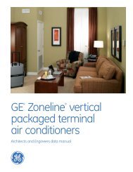
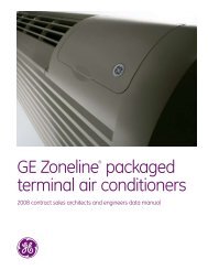
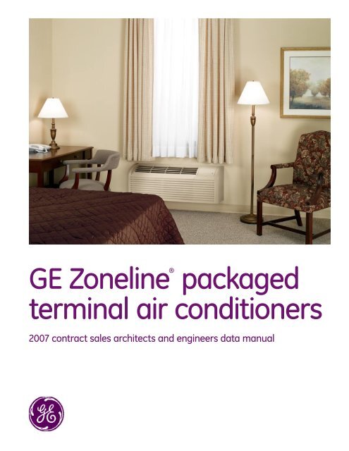
<strong>GE</strong> Zoneline® <strong>packaged</strong><strong>terminal</strong> <strong>air</strong> <strong>conditioners</strong>2007 contract sales architects and engineers data manual
Table of Contentsge.comFront Cover 1Mini Specs 2800, 3800 and 5800 Series 2Mini Specs Power Connection Kits and Nomenclature 3The 2800/3800/5800 and Dry 25 4Table of Contents 5Introduction 6The Zoneline System 7Features and BenefitsFeatures Table 8Features and Benefits 9-11Auxiliary Control Switches 12-13Central Desk Control 14Remote Thermostat Control 15-17Heat Pumps and Energy Savings 18-19Installation and DimensionsApplication Comments 20Case Dimensions 21Wall Case/Sub-Base Installation 22-33Condensate Disposal Systems 4-36Ducted Installations 7-39Exterior Grilles 40-41Product DataElectrical Connection 42Essential Elements Ordering Overview 43Maximum Connected Load 44Cooling/Heat Pump Performance Data 45Latent System Capacity 46Normal Yearly Operating Data 47Schematics 48-50Product SpecificationsSuggested Bid Form Specifications 51-53Zoneline Chassis Nomenclature/Receptacles/Sub-bases 54Specifications 55Complete Accessory List 56General Installation Suggestions 57-58Warranty 58Alphabetical Index 59Back Cover 60Important NoticeEquipment used as a primary source forheating or cooling is an integral part ofthe building in which it is installed. Properapplication is essential for satisfactoryperformance over a wide range ofoperating conditions. It is stronglyrecommended that a professionalengineer determine proper application.If this unit is a replacement unit, itsspecifications and performancemay differ from those of the unit it isreplacing. For that reason, we againstrongly recommend that a professionalengineer determine proper application.
IntroductionThis manual is designed to provide product, performanceand application information to our customers and theirarchitects and engineers for use in selection and designof a zonal comfort control system utilizing <strong>GE</strong> Zoneline ®Packaged Terminal Air Conditioners (PTAC) and PackagedTerminal Heat Pumps (PTHP). <strong>GE</strong> Zoneline PTACs and PTHPsare self-contained units designed for through-the-wallinstallations in hotels, motels, apartments, hospitals,nursing homes, add-on rooms and many other installations.Zonelines provide individual room or zone control in bothcooling and heating operation. There is a model for practicallyevery application, ranging in cooling capacity from 7,100 to14,700 BTUH and heating capacity from 6,400 to 13,400 BTUHin heat pump operation. See pages 33 and 55 for resistanceheaters available.Zoneline offers a two-tier lineup: the Deluxe Line and thePremium Line. The Deluxe Line consists of the 2800 Serieswith electric resistance heat, the 2800 Series Dry Air 25 Modelswith enhanced dehumidification for hot and humid climatesand the 3800 Series heat pump. The 3800 Series heat pumpfeatures reverse cycle defrost and simultaneous supplementalresistance heat, when needed, to maintain room comfort.The Premium Line features the 5800 Series heat pump withreverse cycle defrost and supplemental resistance heat, whenneeded, to maintain room comfort, plus tactile touch controlswith digital display and standard corrosion protection.Deluxe Line Standard Features:• Universal Heaters• 2 Fan Motors• Heat Sentinel• “L” Coil Design Condenser• Locked-In-Place Control Knobs• 3-Position Vent Door• Freeze Sentinel• Indoor Coil Frost Control• Central Desk Control Interface• Remote Thermostat Control Interface• Random Restart• Electronic Temperature Limiting• “Smart Fan” Fan Cycle/Continuous Control• Transfer Fan Interface• Room Occupancy Sensor Interface• Reverse Cycle Defrost and Simultaneous SupplementalResistance Heat on Heat Pumps• Quick Heat RecoveryDeluxe Line Optional Features:• Corrosion Protection• Internal Condensate Removal (on 3800 Series Heat Pumpwithout Corrosion Protection)NOTE: Dry Air 25 models include all the standard features of the 2800 Series plusstandard corrosion protection.Premium Line Standard Features:All the Standard Features of the Deluxe Line Plus:• Two fan motor system with Indoor Cross Flow Blowerfor quieter operation• Digital Controls—LED Temperature Display—Easy Temperature Selection—Tactile Touch Pad• Unit Diagnostics• Standard Corrosion Protection TreatmentPremium Line Optional Features:• Internal Condensate Removal (Not for use in seacoastor corrosive areas)Advantages of the <strong>GE</strong> Zoneline System:• Flexible Application—May be installed from flush to finished floor to 3" fromthe ceiling—7,100 to 14,700 BTUH units in same physical size—Deluxe 2800 and 3800 Series may be ducted to conditionmore than one room—Compatible with Class 2 remote thermostat control—Compatible with 2 wire CDC or many EnergyManagement systems• Economical Installation—No ductwork necessary—No mechanical equipment rooms or pipes required forheating/cooling units—Replacement units fit existing 42"-wide by 16"-highwall cases• Quiet Operation—Indoor double cut-off scroll: two fan motor 2800 and 3800Series units—Indoor cross-flow blower: 2 fan motor 5800 Series units• Energy-Saving Operation—Units in unoccupied areas may be turned off—Designed for efficient cooling operation — EERs from 10.0to 13.0—Efficient heat pump units — COPs from 3.2 to 3.6—Extended heat pump operation without sacrificingroom comfort• Ease of Maintenance—Permanently lubricated fan motors—Upfront lift-out interchangeable filters—Air Discharge area is easily accessed for cleaning—Slide-out chassis for easy access for cleaning or ifservice is required• Reverse Cycle Heat Pump OperationBoth the 3800 and the 5800 Series heat pumps utilizethe unique <strong>GE</strong> PTAC heat pump operation to ensure acomfortable room. The logic used by the units is thesame logic used by central system heat pumps toprovide greater savings.
The Zoneline ® Systemge.comThe typical Zoneline installation consists of the wall case (or sleeve), chassis, and exterior grille. Some installations mayuse a sub-base for support of the unit or for ease of electrical connections. Each of the components should be the standardproducts offered by <strong>GE</strong> or, in the case of the exterior grille, approved by <strong>GE</strong> Applications Engineering. Use of components notspecifically designed or approved for use with the Zoneline can result in unsatisfactory operation and can be the cause offailure not covered by the warranty.Components of the Zoneline SystemTypical Installation (Deluxe Series shown)ChassisRoom CabinetWall CaseRAB71A (Steel-Insulated)RAB77 (SMC — Molded)Wall Case Options(See page 22)RAG67 (shown)Grill Options(See page 40)Optional Accessories of the Zoneline SystemPower Connection Kit (required on all units)Line Cord Kit shownSee pages 42-43Power Supply CordChasewayRAK204D20P Sub-Base (shown)RAK6052 Duct Adapter(For Deluxe Series)Power Supply Cord (included with 208v/230vsub-bases)RAK601/602 (For Deluxe Series)Duct Extension, Register and Trim FlangeSee pages 23 and 33 for information on electrical sub-bases and chaseway.See pages 37-39 for information on ducted installations.
Zoneline ® FeaturesAZ AZ AZ2800 800 5800Enhanced Dehumidification — Dry Air 25 Optional N/A N/ACooling EER Range (230 Volts/265 Volts) 10.2 - 12.7 10.0 - 12.7 10.2 - 13.0Heating COP Range (230 Volts/265 Volts) N/A .2 - 3.6 .2 - 3.6Heat Source — Electric Resistance Heat Standard — —Heat Source — Heat Pump With SelectableFull Time or On Demand Simultaneous/Supplemental Resistance Heat — Standard StandardStaged Heating — Stage StageUniversal Heater — UPC* Standard Standard StandardUnit Controls Rotary Knobs Rotary Knobs Touch PadElectronic Temperature Selection(Slews Up & Down) with Digital Display — — StandardUnit Diagnostics — — StandardHighly Featured Microprocessor Controls Standard Standard Standard-PlusElectric Resistance Heat Lock-Out (above 46°F) — Standard StandardAutomatic Emergency Heat — Standard StandardHeat Pump Defrost System — Reverse Cycle Reverse CycleHigh Temperature Operation Protection — Standard StandardQuick Heat Recovery — Standard StandardTemperature Boost Selectable SelectableService Indicator — — Temp Display BlinksFan Motors — Permanently Lubricated 2 2 22-Speed Outdoor Fan Standard Standard StandardIndoor Fan Speed Selections — HIGH/LOW Standard Standard HIGH/LOW/AUTOFan Only Setting — HIGH/LOW Standard Standard StandardFan Cycle Switch “Smart Fan” “Smart Fan” “Smart Fan”Constant-Run Fan Selectable Selectable SelectableRotary Compressor Standard Standard StandardAutomatic Compressor Restart Delay Standard Standard StandardFreeze Sentinel Standard Standard StandardHeat Sentinel Standard Standard StandardIndoor Coil Frost Control Standard Standard StandardTransfer Fan Connections Standard Standard Standard7-Step Electronic Temperature Limiting Standard Standard StandardRemote Control Capability with Wall Mounted Thermostat Standard Standard StandardCentral Desk Control Capability Standard Standard StandardEnergy Management System Interface with Load Shedding Option Standard Standard StandardReversible Indoor Air Louvers 40º/50º Standard Standard StandardUp-Front Filters Standard Standard StandardEasy-Clean Air Discharge Area Standard Standard —Concealed Manual Vent Control Standard Standard StandardDucted Installation Capability RAK6052 RAK6052 —Corrosion Protection (Standard on Dry Air 25) Optional Optional StandardInternal Condensate Removal (ICR) (Factory Installed Option.Cannot be used in Corrosion Areas.) N/A Optional Optional*UPC — Universal Power Cord Connection (See pages 42 and 55).265-volt units must be connected in a manner to meet National Electrical Code and all local codes.
Features and BenefitsStandard Physical Dimensions<strong>GE</strong> has maintained the same dimensions since 1961 —42" wide x 16" high x 13-3/4" deepReplacement of older units is made easy.Weather-Protected Electrical ComponentsVital electrical components are protected from the weatherby locating them on the indoor side of the weather barrier.Weather-Resistant “Superseal”Properly installed unit in undistorted case keeps <strong>air</strong> leakageto a minimum.7 CFM <strong>air</strong> infiltration with 25 MPH wind on non-ICR units —10 CFM on units with ICR.Industry specification is 19 CFM of <strong>air</strong> infiltration.Heater Sizes to Meet Room RequirementsAll units are equipped with a universal heater —the resistance heat output is determined by powerconnection kit.230/208-volt — Line Cord Connected Units — 2.55/2.09 KWwith RAK3153 — 15-amp circuit; 3.45/2.82 KW withRAK3203 — 20-amp circuit; 5.0/4.09 KW with RAK3303 —30-amp circuit.230/208-volt - Sub-Base Connected Units — 2.55/2.09KW with RAK204D15P — 15-amp circuit; 3.45/2.82 KWwith RAK204D20P — 20-amp circuit; 5.0/4.09 KW withRAK204D30P — 30-amp circuit.265-volt — 2.55 KW with RAK5172 — 15-amp circuit; 3.45 KWwith RAK5202 — 20-amp circuit; 5.0 KW with RAK5302 —30-amp circuit.Unit Controls2800 and 3800 Series — locked-in-place rotary knobs fortemperature and operation selection.5800 Series — touch pad controls with digital readout oftemperature set point.Highly Featured Microprocessor ControlsMicroprocessor controls are programmed to interface withthe temperature sensors to maximize comfort conditions forthe room occupant and provide outstanding features.Thermistors are used to sense small changes in temperatureto give excellent room control and allow the microprocessorto monitor and react to changing conditions.Electric Resistance Heat Lock-OutTo maximize the savings of the heat pump operation, theZoneline heat pumps do not utilize the resistance heaterwhen the outdoor temperature is above 46°F during normaloperation. The resistance heat is used in the Quick HeatRecovery feature.Automatic Emergency HeatAutomatically uses electric resistance heat if the heatpump output is not sufficient to maintain selectedroom temperature.ge.comReverse Cycle Heat Pump Defrost SystemStandard on all Zoneline 3800 and 5800 Series heat pumps.Enables heat pump to operate at lower temperatureswhen other systems switch to more expensive electricresistance heat.See pages 18 and 19 for discussion of heat pump operationand defrost systems.High Temperature Heat Pump Operation ProtectionAutomatically protects the compressor if heat pump isoperated with high outdoor temperatures.Power to the outdoor fan is turned off if the indoor coil getstoo hot during heat pump operation to prevent damage tothe compressor.Quick Heat Recovery – Heat Pump UnitsWhen the unit operation is changed from STOP or COOL toHEAT, the electric resistance heaters are used to warm theroom to the thermostat set point. This provides faster roomtemperature increase for greater guest comfort.Unit DiagnosticsThe 5800 Series has a dip switch that activates each ofthe various components of the unit to operate briefly. Thisenables the technician to determine if individual componentsare functioning properly.Service IndicatorOn the 5800 Series, if the microprocessor detects acompressor malfunction, the digital temperature displaywill blink. If the malfunction occurs during cooling operation,the indoor fan will continue to operate. If the compressormalfunctions in heating mode, the unit will automaticallyswitch to resistance heat to maintain room temperature setpoint. <strong>GE</strong> Service should be called to check the Zoneline.Fan Motors – Permanently LubricatedAll units have two fan motors for quiet operation andmaximum operating efficiency.Motors are permanently lubricated to reduce maintenanceand totally enclosed to keep dirt and water out of the motorwindings.2-Speed Outdoor FanThe unit automatically selects the most efficient speed forthe outdoor fan. The operating sound level is lower when theoutdoor fan can operate in low speed yet there are situationswhere it must operate in high speed. The unit changes thefan speed automatically.Indoor Fan Speed Selections – HIGH/LOWUnit may be operated in HIGH HEAT or LOW HEAT or HIGHCOOL or LOW COOL.
Features and BenefitsFan-Only Setting – HIGH/LOWThe unit provides the option of selecting either HIGH or LOWspeed for Fan-Only operation.Fan-Cycle Switch – “SmartFan”Unique “SmartFan” allows unit to operate fan continuous incooling operation and fan cycle in heating to provide betterguest comfort. Eliminates complaint of cold <strong>air</strong> draft duringheating operation.Eliminates need of changing fan-cycle switch seasonally.“SmartFan” settings are controlled by two dip switches onauxiliary control panel.Compressor Random RestartIn the event of a power failure, all compressors attemptingto restart immediately when power is restored can resultin a power surge that can cause another power interruption.The microprocessors in the Zonelines have a random restartlogic system that prevents all units from starting at thesame time.Rotary CompressorSmoother operation for quiet, dependable service. <strong>GE</strong> hasused rotary compressors since 1961.Compressor Restart DelayZonelines are designed to provide a minimum of threeminutes of compressor off time to allow refrigerant pressuresto equalize before restarting to prevent compressor damage.Zonelines are also designed to provide a minimum of threeminutes of compressor run time to prevent room occupantdisturbance due to short-cycling of the <strong>air</strong> conditioner.Freeze Sentinel Detects low room temperature and turns on heater tohelp protect against damage caused by freezing roomtemperature.Heater turns on at 41°F and warms indoor thermistortemperature to 46°F and shuts off.Freeze Sentinel may be turned off by dip switch onauxiliary control.Heat SentinelThe property owner may choose to activate the HeatSentinel feature on the Zoneline. If the Heat Sentinel isactivated and room temperature reaches 85°F while theunit is in the “STOP” setting, the unit will automatically startin <strong>air</strong> conditioning operation and will shut off when the roomtemperature reaches 80°F. This will help dehumidify the <strong>air</strong>and lower high temperatures so the guest will not be enteringan extremely hot room.Indoor Coil Frost ControlTransfer Fan InterfacePrevents indoor coil from freezingand causing complaints due to lackof cooling. Frost can form on theindoor coil when the unit is operatedin cooling when outdoor temperaturesare low. The unit automatically shutsthe compressor off until the indoor coiltemperature warms to the point wherefrosting will no longer occur.24 VAC <strong>terminal</strong>s are provided to operate a relay to controla fan mounted in a wall to move conditioned <strong>air</strong> intoanother space. The electrical power for the operation of thetransfer fan itself is not provided by the Zoneline. Transferfans and their controlling relays are field supplied.Electronic Temperature LimitingSeven independent programmable heating temperature limitsand seven independent programmable cooling temperaturelimits. Eliminates need to reset the limits seasonally.Remote Control Capability with Wall-MountedThermostatSee pages 15-17.Central Desk Control CapabilitySee page 14.Heating Temperature LimitsEnergy Management System Interface withLoad Shedding OptionAll units have a switch on the auxiliary control panel toallow the indoor fan to continue operating if the unit isconnected to an Energy Management System that shutsoff compressor or heater operation. By allowing the indoorfan to run when the heater or compressor is shut off bythe Energy Management System, the guest is less likely torealize the operation of the unit has been altered. This helpsreduce peak energy demand loads without disturbing theroom occupant.Reversible Indoor Air LouversAllows <strong>air</strong> to be directed into room at 40º or 50º angle toprovide better <strong>air</strong> distribution.Angle is changed by removing room front and screwsholding louver in place, and rotating louver section.HighestHeat65 70 72 74 76 78 80 85LowestCoolCooling Temperature Limits60 64 66 68 70 72 74 76Limits are set by dip switches on auxiliary control panel.10
Features and BenefitsEasy Clean Air Discharge AreaUp-Front Air FiltersTwo interchangeableup-front filters, easyto remove and reinstall,may be cleaned withoutopening or removingthe room front.Clean filters by brushing,vacuuming or backflushingunder faucetor shower head.2800 and 3800 Series units have an out-of-sight verticalprotective screen over the indoor fan. This allows easycleaning of <strong>air</strong> discharge area by simply removing roomfront and wiping clean.There is no screen directly below discharge louver to trapunsightly dirt and debris where it may be seen by roomoccupant.Concealed ManualVent ControlThe 3-position manual ventdoor control may be closed,partially open or fully open.Vent CFM High SpeedUnit Full Open Partial Open7000 50 409000 70 4512000 75 4515000 75 45CFM ratings at 230 volts and 265 volts.Greater amounts of <strong>air</strong> will be introduced if the room has anexhaust fan.An open vent door brings unconditioned outdoor <strong>air</strong> into theroom, increasing heating and cooling costs.Positive vent door closure prevents accidental opening andunwanted <strong>air</strong> infiltration.Corrosion Protection (Optional)ge.com2800 and 3800 Series units may be ordered with specialprotection to better withstand damage from salt <strong>air</strong> andsalt water in seacoast areas.Corrosion protection is standard on the 5800 Series andon Dry Air 25 models.Heat Pump units with ICR are not available with corrosionprotection and should not be installed in seacoast orcorrosive environments.Units installed in corrosive areas should be examined andcleaned more frequently than normal installations.Internal Condensate Removal (ICR)See page 34 for a discussion of the Internal CondensateRemoval system available on 3800 and 5800 Series heat pumps.Enhanced DehumidificationMoisture removal is an important function of an <strong>air</strong>conditioner. People are more comfortable at highertemperatures when the humidity level is relatively low.Air <strong>conditioners</strong> operate with less energy consumptionwhen the room temperatures are set higher.The <strong>GE</strong> Zoneline ® 2800 Series with the Dry Air 25 heat pipeapplication removes 25% more moisture than the base2800 Series unit.The <strong>GE</strong> Zoneline Dry Air 25 chassis is the only PTAC availablewith the application of the patented Dinh ® DehumidifierHeat Pipe under license from Heat Pipe Technology, Inc.Customers who are using the Dry Air 25 report a freshersmellingroom as a result of the lower humidity levels, aswell as lower operating costs.Locking Door KitRAK8023 — A door with a lock that replaces the standardcontrol cover door to prevent unauthorized changing ofcontrol setting is offered as an accessory.11
Auxiliary Control SwitchesThese switches are located behind the room cabinet under the control panel.2800 and 3800 SeriesSwitches DescriptionLeft Switches(1) ALL I2R Heat pump override —Down — Normal heat pump operationUp — resistance heat only (3800 Series only)(2) C: FAN Fan control for cooling operation —Down — Fan ContinuousUp — Fan Cycle(3) H: FAN Fan control for heating operation —Down — Fan CycleUp — Fan Continuous(4) CLASS 2 Remote Thermostat Mode —Down — Unit ControlUp — Remote Thermostat(5) LOAD SHED Load Shedding when connected to Central Desk Control System —Down — Fan shuts off with unitUp — Fan under “Smart Fan” settings(6) FREEZ S Freeze Sentinel Override —Down — Freeze Sentinel ONUp — Freeze Sentinel OFF(7) CONST FAN Constant Fan —Down — Fan runs normallyUp — Fan runs when unit is in STOP position(8) OCCUPIED Occupancy Sensor Mode —Down – Unit ControlUp — Occupancy Sensor ConnectedRight SwitchesTL1 – TLCooling temperature limiting (See table at bottom of page)TL4 – TL6Heating temperature limiting (See table at bottom of page)(7) Heat Sentinel switch —Down — Heat Sentinel OFFUp — Heat Sentinel ON(8) Heat Boost (3800 series only) —Down — Heat Boost OFUp — Heat Boost ONAuxiliary (2800 and 3800 series)3800 Series shownUPDOWNALLI 2 R (All Electric Heat)(3800 Series models only)C: FAN CN (Cooling–Smart Fan)H: FAN CY (Heating–Smart Fan)CLASS 2 (Remote Thermostat)LOAD SHEDDING (CDC)FREEZ Sen (Freeze Sentinel)CONST FAN (Constant ON Fan)OCCUPIED (Occupancy Sensor)HIGH1 2 3 4 5 6 7 8 1 2 3 COOL 4 5 67 8UPDOWNHEAT BOOST(3800 Series models only)Heat SentinelTL1 (H) (Temp. Limit 1–Heat)TL2 (H) (Temp. Limit 2–Heat)TL3 (H) (Temp. Limit 3–Heat)TL1 (C) (Temp. Limit 1–Cool)TL2 (C) (Temp. Limit 2–Cool)TL3 (C) (Temp. Limit 3–Cool)Cooling and Heating temperature limits are set independently, temperature limitingswitches are in factory-set down position, except as noted.12Cooling Temperature LimitsSwitches Up NONE 1 1, 2 2 2, 3 1, 2, 3 1, 3 360 64 66 68 70 72 74 76Heating Temperature LimitsSwitches Up 6 4, 6 4, 5, 6 5, 6 5 4, 5 4 NONE65 70 72 74 76 78 80 85
Auxiliary Control Switchesge.comThese switches are located behind the room cabinet under the control panel.5800 SeriesSwitches DescriptionLeft Switches(1) ALL I2R Heat pump override —Down — Normal heat pump operationUp — resistance heat only(2) C: FAN Fan control for cooling operation —Down — Fan ContinuousUp — Fan Cycle(3) H: FAN Fan control for heating operation —Down — Fan CycleUp — Fan Continuous(4) CLASS 2 Remote Thermostat Mode —Down — Unit ControlUp — Remote Thermostat(5) LOAD SHED Load Shedding when connected to Central Desk Control System —Down — Fan shuts off with unitUp — fan under “Smart Fan” settings(6) FREEZ S Freeze Sentinel Override —Down — Freeze Sentinel ONUp — Freeze Sentinel OFF(7) CONST FAN Constant Fan —Down — Fan runs normallyUp — fan runs when unit is in STOP position(8) OCCUPIED Occupancy Sensor Mode —Down — Unit ControlUp — Occupancy Sensor ConnectedRight SwitchesTL1 – TLCooling temperature limiting (See table at bottom of page)TL4 – TL6Heating temperature limiting (See table at bottom of page)(7) Diagnostics Switch(8) Heat Sentinel switch —Down — Heat Sentinel OFFUp — Heat Sentinel ON(9) Heat Boost —Down — Heat Boost OFFUp — Heat Boost ON5800 Series shownUPDOWNALLI 2 R (All Electric Heat)(5800 Series models only)C: FAN CN (Cooling–Smart Fan)H: FAN CY (Heating–Smart Fan)CLASS 2 (Remote Thermostat)LOAD SHEDDING (CDC)FREEZ Sen (Freeze Sentinel)CONST FAN (Constant ON Fan)OCCUPIED (Occupancy Sensor)HIGH1 2 3 4 5 6 7 8 1 2 3 COOL 4 5 6Cooling and Heating temperature limits are set independently, temperature limitingswitches are in factory-set down position, except as noted.Cooling Temperature LimitsSwitches Up NONE 1 1, 2 2 2, 3 1, 2, 3 1, 3 360 64 66 68 70 72 74 76Heating Temperature Limits7 8 9Switches Up 6 4, 6 4, 5, 6 5, 6 5 4, 5 4 NONE65 70 72 74 76 78 80 85UPDOWNHEAT BOOST(5800 Series models only)Heat SentinelDiagnostics SwitchTL1 (H) (Temp. Limit 1–Heat)TL2 (H) (Temp. Limit 2–Heat)TL3 (H) (Temp. Limit 3–Heat)TL1 (C) (Temp. Limit 1–Cool)TL2 (C) (Temp. Limit 2–Cool)TL3 (C) (Temp. Limit 3–Cool)13
Central Desk ControlSome installations may want to govern the ability of the unitto operate from a control device remote to the unit or evenremote to the room in which the unit is located. The generalterm given to systems such as this is Central Desk Control.The most common installation of this type of system is aswitch mounted at the registration desk and, upon guestcheck-in, a button is pushed or a switch is moved to allowthe <strong>air</strong> conditioner to operate. Likewise, when the guestchecks out the device is put into the “OFF” position so theunit will not operate while the room is vacant.It is not necessary that the controlling device be locatedat a central desk to employ a device that will control theunit operation. For instance, in some resort areas devicesare connected to sliding glass doors and opening the doorcauses a contact to close, turning the <strong>air</strong> conditioner off.This prevents energy being wasted by operating the <strong>air</strong>conditioner when warm, humid <strong>air</strong> is entering the room.Some systems operate by motion sensors or heat sensingdetectors mounted in the room. These types of systemsdetermine occupant presence in the room and allow theunit to operate; if no one is in the room the device signalsthe <strong>air</strong> conditioner to turn off.Zoneline ® models offer Load-Shedding capabilities onunits connected to Central Desk Control Systems. For moreinformation on the models’ Load-Shedding Feature, seepage 10.There is a wide variety of devices available, each withits own benefits and constraints. While <strong>GE</strong> does not offercomponents that are external to the unit for a Central DeskControl (CDC) system, <strong>GE</strong> Zonelines are compatible with mostCDC and Energy Management systems. Zonelines provide a24 VAC circuit that powers the Central Desk Control systemand no external power is needed.All Zoneline 2800, 3800, and 5800 Series units are compatiblewith simple on/off 2-wire Central Desk Control systems.Consult with the provider of other energy managementsystems to be sure they are compatible with the <strong>GE</strong> Zoneline.Zonelines have standard connectors factory-installed toprovide a CDC interface that permits the unit to be connectedto most of the energy management systems. The devicesconnected to the Zoneline units require no power supply ortransformers external to the unit.Important CDC Comments (all series applicable)1. When the switching device closes the circuit of the CDCconductors, the unit operation stops.2. Do not use a common buss (at the unit or at the switchpanel) in the wiring. Both wires comprising the circuit mustconnect to the unit connectors and to the controllingswitch. Running one wire from one unit to another unit iscommon bussing and may damage internal componentsor cause erratic operation of the system.3. A 24-volt transformer is contained within the Zoneline.No external voltage may be applied to the unit throughthe CDC <strong>terminal</strong>s. (Voltage on the CDC conductors is24 volts AC.)4. Recommended wire size must be followed as a minimumrequirement.Wire Size #AWG Maximum Allowable Length#22 600 Ft.#20 900 Ft.#18 1500 Ft.#16 2000 Ft.Freeze Sentinel remains operational when the unit isconnected to a CDC system. Even if the unit is turned “OFF” atthe central location, if the sensor at the unit detects the lowtemperature, the electric resistance heaters and the fan willautomatically turn on.Connecting the Zoneline to a CDC system does not eliminatethe ability to connect the unit to a remote thermostat.Once the circuit is “opened,” and control of the unit removedfrom the CDC system, the selected controls - either the unitmounted control or the remote thermostat - govern theoperation of the unit.Please see page 57 for installation recommendations forthe Central Desk Control wiring.CDC Terminal Location and Typical WiringSee page 15 for location of CDC <strong>terminal</strong>s on unit.Example of Common BussingNOT PERMITTEDUnit #1 Unit #2 Unit #3INCORRECT Common BussingNormally OpenSwitch -Unit OperationalCDC Terminalson ZonelineTypical Wiring(All Wiring Shown Is Field Supplied)14
Remote Thermostat ControlIn some installations, control of the operation of the unit ata location remote from the unit itself may be desired. A unitmounted high in the wall or over a door, for instance, wherethe unit-mounted controls are inaccessible, can be connectedto a wall-mounted thermostat. Other installations may useremote thermostat control for design or performanceenhancement. The unit is connected to the thermostat bylow-voltage wiring which permits the operation of the unit tobe selected and the temperature sensed at the thermostat.Important Notes: Remote thermostat wiring should not berun through wall case. Thermostat wiring should exit thewall below the unit and enter the unit between room cabinetand chassis. Wire molding may be used to hide thermostatwiring. If a sub-base is used, the thermostat wiring may beconcealed by the sub-base. Thermostat wiring should not berun parallel to line voltage wires since induced current maycause erratic operation.All Zoneline 2800, 3800 and 5800 Series units are adaptableto Class 2 remote low-voltage thermostat. The only additionalfield-supplied components are the remote thermostat andwiring necessary to connect it.The controls on the unit are not functional when the remotecontrol function is used.Resistance Heat ModelsThe Zoneline 2800 resistance heat units may be connected toa single-stage thermostat designed for use with cooling withelectric heat systems. <strong>GE</strong> offers three thermostatscompatible with the 2800 Series unit.The AC voltage may not be compatible with somesolid-state thermostats.ge.comThe fan speed for the 2800 Series in remote thermostatoperation is selected by the connection of the fan wire fromthe thermostat to either the HIGH or LOW <strong>terminal</strong> on the unit.See the sketch of the unit <strong>terminal</strong>s for the location of the HIGHand LOW fan-speed <strong>terminal</strong>s. Operating the unit in low fanspeed reduces the operating sound level of the unit.Freeze Sentinel remains operational if the unit is connected toa remote thermostat. The unit may be connected to a CentralDesk Control (CDC) system and controlled with a remotethermostat when the CDC system has the unit in operation.See page 14 for additional information on the CDC system.Unit temperature limiting switches are not functional whenunit is connected to a remote thermostat.Field Wiring TerminalR — 24V ACGL — Low-Speed FanGH — High-Speed FanB — Not Used on 2800Y — CompressorW — HeaterC — Common — GroundRAK163A1 —a mechanicalmanualchangeoverthermostatrequiring fourconnection wires.RAK164D1 —a solid-statedigital manualchangeoverthermostatrequiring fiveconnection wires.RAK164P1 —a solid-state digitalprogrammableauto-changeoverthermostatrequiring fiveconnection wires.The Class 2 Mode Switch (dip switch #4 on the auxiliary controlboard) must be set to the ON/UP mode to enable remotethermostat control. Refer to installation instructions <strong>packaged</strong>with the chassis.Please see page 57 for installation recommendations forthe remote thermostat wiring.Compatibility of other thermostats considered for use with the<strong>GE</strong> Zoneline is the responsibility of the customer. The controlvoltage on the remote control conductors is 24 volts AC.RCDCGLRGHGLBGHResistance Heat ModelsYBWYCWCRAK806 Universal Control Cover LabelWhen a Zoneline unitis using a remotethermostat control,the RAK806 UniversalControl Cover Labelis recommended. TheRAK806 is onlyavailable in apackage of 10 labels.The label is placedover the controlpanel directing theHeat user Pump to the Models wallthermostat foroperation of theZoneline unit.Common — GroundWhite — HeaterYellow — CompressorBlack — Not Used On 2800Green — High-Speed FanGreen — Low-Speed FanRed — 24V ACCDC TerminalCommon — GroundWhite — HeaterYellow — CompressorBlack — Reversing ValveGreen — High-Speed FanGreen — Low-Speed FanRed — 24V AC15
Remote Thermostat ControlHeat Pump ModelsThe Zoneline ® 3800 and 5800 Series heat pump units maybe connected to a single-stage cooling/two-stage heatingthermostat designed for use with heat pump systems. <strong>GE</strong>offers 3 thermostats compatible with the 3800 and 5800series units:RAK147 —mechanicalmanualchangeoverthermostatrequiring 6connection wires.RAK148D1 —solid-state digitalmanualchangeoverthermostatrequiring 6connection wires.RAK148P1 —solid-state digitalprogrammableauto-changeoverthermostatrequiring 6connection wires.Please see page 57 for installation recommendations for theremote thermostat wiring. Compatibility of other thermostatsconsidered for use with the <strong>GE</strong> Zoneline ® is the responsibilityof the customer.The control voltage on the remote control conductors is 24 VAC.The Class 2 Mode Switch, dip switch #4 on the auxiliary controlboard on both the 3800 series and the 5800 series, must be setto the ON/UP mode to enable remote thermostat control. Referto installation instructions <strong>packaged</strong> with the chassis.The fan speed for the 3800 and 5800 series in remotethermostat operation is selected by the connection of thefan wire from the thermostat to either the HIGH or LOW<strong>terminal</strong> on the unit. See the sketch of the unit <strong>terminal</strong>sfor the location of the HIGH and LOW fan speed <strong>terminal</strong>s.Operating the unit in low fan speed reduces the operatingsound level of the unit.When connected to a remote thermostat, the indoor <strong>air</strong>temperature sensing is shifted from the unit to the remotethermostat. For this reason, the units will operate slightlydifferently when connected to a remote thermostat. Thefollowing chart shows the unit operation when connectedto a remote thermostat.Temperature Boost option should not be used with remotethermostat operation since this will cause the unit to switch toresistance heat when outdoor temperatures are below 46ºF.Feature Heat Pump Electric HeatIndoor Frost Control Yes YesFreeze Sentinel Yes YesAuto Fan Speed No NoElectronicTemperature Limiting NoNoSwitch to ResistanceHeat Based On Indoor Determined byTemperature Remote Thermostat N/ASwitch to ResistanceHeat Based OnOutdoor Temperature YesN/AReverse Cycle Defrost YesN/ASimultaneousResistance Heatwith Heat Pump No N/AResistance HeatLockout Yes N/ACommon — Ground“Smart Fan” Fan ON/AUTO Set On White Fan — Heater ON/AUTO Set OnFan CycleRemote Thermostat Yellow Remote — Compressor ThermostatCentral Desk Control Yes Black Yes — Not Used On 2800Green — High-Speed FanGreen — Low-Speed FanField Wiring TerminalRed — 24V ACR — 24V AC GL — CDC Low-Speed Terminal FanGH Resistance — High-Speed Heat Models Fan B — Reversing ValveY — Compressor W — HeaterC — Common - GroundRCDCGLRGHGLBHeat Pump ModelsGHYBWYCWCCommon — GroundWhite — HeaterYellow — CompressorBlack — Reversing ValveGreen — High-Speed FanGreen — Low-Speed FanRed — 24V ACRemote Thermostat Control Selection Chart For Zoneline Packaged Terminal UnitsZoneline Series Thermostat Model Type Function Low-Voltage Conductors2800 RAK163A1 Mechanical4RAK164D1 Digital Cooling and Heating5RAK164P1 Digital Programmable 53800 and 5800 RAK147 Mechanical6RAK148D1 DigitalSingle Stage Cooling –2 Stage Heating6RAK148P1 Digital Programmable 6Thermostat wire size – up to 60 feet AWG20 – up to 66 feet AWG1816
Remote Thermostat ControlMultiple Units Connected to One Remote Thermostat(2800 Series)One remote control thermostat may be used to controlmultiple resistance heat Zoneline units, however the unitsmay not be wired direct. Since each Zoneline unit has ange.comintegral transformer, direct wiring can result in a “bucking”or boosting” voltage condition, and is in violation of theNational Electric Code. The diagram below shows thecorrect wiring for such an installation through the useof field supplied isolation relays.For Use With Mechanical 4-Wire Systems OnlyRemote Control (Low Voltage) WiringOne stage Thermostat Controlling Three Zoneline UnitsResistance Heat Zoneline 2800 Series Units(Not Applicable on Heat Pump Units)Field-Supplied Relay SpecificationsNumber OfUnits ControlledRelay DesignationR1, R2, And R32 POTTER and BRUMFIELD TYPE KA11AY-24 OR EQUIVALENT3 POTTER and BRUMFIELD TYPE KA14AY-24* OR EQUIVALENT4 POTTER and BRUMFIELD TYPE KU17A11-24* OR EQUIVALENTMORE THAN 4NOTE: Current draw through thermostat contacts should not exceed 1.0 amps.*Special order, 100 piece minimum order.USE COMBINATION OF RELAYS SPECIFIED ABOVE17
Heat Pumps and Energy Savings• <strong>GE</strong> Zoneline ® Heat Pumps are designed to providecost-efficient heat pump operation while monitoringroom conditions to maintain comfort.The units employ a logic system monitoring both outdoorand indoor temperatures to determine the heat source, thusincreasing energy savings by operating longer in the heatpump mode.Heat pumps save energy and cost less to operate thanunits with electric resistance heaters as the only heat source.Just as the EER of an <strong>air</strong> conditioner is an indication of theefficiency of the unit, COP (Coefficient of Performance) is theindication of the efficiency of the heat pump. This relativeefficiency of a heat pump compares the unit to electricresistance heat. If a unit has a COP of 3.0, it means theunit will produce three times as much heat at ratingconditions for the same electrical input wattage usedfor electric resistance heat.The compressor is used in heat pump operation just asin <strong>air</strong> conditioning operation. In heat pump operation,the hot refrigerant gas is directed to the indoor coil ratherthan to the outdoor coil. Room <strong>air</strong> that circulates over theindoor coil gains heat from the coil rather than losing heatto the coil as during cooling operation.As the outdoor temperature falls, the heat pump is able toextract less heat from the outdoor <strong>air</strong> to raise the temperatureof the indoor <strong>air</strong>. For this reason, all <strong>packaged</strong> <strong>terminal</strong> heatpumps also have electric resistance heaters as backup to heatpump operation. At some point, the heat pump is unable toprovide sufficient heat to adequately warm the room. ManyPackaged Terminal Heat Pumps cease heat pump operationand change to more expensive resistance heat at somepre-determined outdoor temperature to compensate forthe inability of the heat pump to maintain room temperature.This point, called the “switchover point,” is usually at anoutdoor temperature where savings from heat pumpoperation may still be realized, if the unit is designed tomaintain room comfort at the lower outdoor temperatures.Balance PointAn important consideration of the selection of a heat pumpunit is the “balance point” of the installation. Virtually everyroom is unique — with different insulation — different sizesand types of windows — different types of construction— different directional exposures. All of these variables, aswell as geographical location, must be considered in order todetermine the balance point, the point at which the heat pumpis unable to produce enough heat to compensate for the heatloss of the room or area being heated. For these reasons aconsulting engineer should be engaged to calculate the heatloss and specify the heat pump unit required.<strong>GE</strong> offers two series of Zoneline Heat Pump units — the3800 Series with Standard Microprocessor controls and the5800 Series with Highly Featured Microprocessor controls— and both series react to the indoor temperature as wellas the outdoor temperature in determining the heat sourceto provide comfortable room conditions and energy savings.This determination of the heat source based on the indoortemperature helps provide a more comfortable room.18
Heat Pumps and Energy SavingsHeat Pump Operation —Zoneline 3800 and 5800 SeriesHeat sources: Heat pump, heat pump and simultaneouselectric resistance heat or electric resistance heat.Zoneline heat pumps employ a highly featured microprocessorcontrol system interfaced with thermistors to accuratelymeasure indoor <strong>air</strong> temperature, outdoor <strong>air</strong> temperature,indoor coil temperature and outdoor coil temperature. Thissystem allows the microprocessor to precisely and predictablyreact to changing conditions in order to provide a veryadvanced Packaged Terminal Heat Pump operating system.The Zoneline heat pumps are designed to help ensure acomfortable room. When “HEAT” is selected, the unit willdetermine if the room <strong>air</strong> is warm enough to satisfy thethermostat setting. If the temperature at the unit sensoris below the desired temperature, the electric resistanceheater will be utilized to warm the room to the point wherethe thermostat is satisfied. This feature is designed to allowthe temperature of an unoccupied room to be maintainedat an energy-saving level without inconveniencing the roomoccupant. Once the thermostat has been satisfied, theresistance heater will turn off and the heat pump will operateas shown in the Heat Source Logic chart until the thermostatcalls for heat again. The unit will operate in this manner evenif connected to a Central Desk Control.Zoneline Heat Pump Heat Source LogicROOMTEMPERATUREVS. THERMOSTATSET POINTLess Than1.8°F Below1.8°F to 2.7°FBelowMore than 2.7°FBelowAbove46°FHeat PumpHeat PumpHeat PumpBetween 46°Fand 25°FHeat Pump*Heat Pump +SupplementalHeaterFull ResistanceHeatBelow25°FFull ResistanceHeatFull ResistanceHeatFull ResistanceHeat*If the “Temperature Boost” switch (dip switch #8) is inthe “ON” position the supplemental simultaneous heaterwill be used with heat pump operation. Simultaneoussupplemental heater: 1.0 KW @ 230 V; 0.8 KW @ 208V; 1.0KW @ 265V.The “Temperature Boost” option utilizes the supplementalsimultaneous heater simultaneously with heat pumpoperation when the outdoor temperature is below 46°Fregardless of the indoor <strong>air</strong> temperature. The chart aboveindicates the heat source of the heat pump under variousindoor and outdoor conditions. The unit is designed toprovide heat pump savings without sacrificing room comfort.ge.comThe Quick Heat Recovery feature is not affected by the HeatSource Logic shown in the chart above. For more informationabout the Quick Heat Recovery Feature, see page 9. Thefull heat output of the resistance heater is dependent uponcircuit amperage and the power connection kit used. Seepages 3 and 42-43 for information on power connection kitsand available heater capacities.A heat pump switch is provided in the auxiliary controls toallow the unit to operate only in resistance heat. The use ofthis option significantly increases the cost for heating.Heat pump defrost — Zoneline 3800 and 5800 SeriesZoneline heat pumps utilize a reverse-cycle demand defrostsystem to extend heat pump operation and increasesavings from extended operation. The microprocessordetermines the need for defrosting by criteria basedon continuous compressor running time, outdoor <strong>air</strong>temperature, outdoor coil temperature and the rate oftemperature change of the outdoor coil. When defrostingis required, the unit reverses the flow of refrigerant to directthe hot gas into the outdoor coil to melt the frost build-up.Before and after the reverse-cycle defrosting, the unit shutsoff the compressor to allow the refrigerant pressuresto equalize throughout the system. This eliminates thepossibility of a loud reversing noise. During these periodsof pressure equalization, the full resistance heat capacityof the unit is activated to help ensure room comfortconditions during the defrost cycle. The unit remains inthe defrost cycle for a minimum of two minutes up to amaximum of nine minutes. The defrost cycle terminateswhen the outdoor coil reaches a temperature of 68°F or themaximum time has been reached.Heat pump condensateSee page 34 for information on heat pump condensate.The Zoneline 3800 Series heat pumps may be ordered witha factory-installed Internal Condensate Removal (ICR) systemto minimize the amount of condensate water draining fromthe unit during heat pump operation. The ICR system hasproven to be an effective means of minimizing the amount ofheat pump condensate dripping from the unit. However, if therequirements of a particular installation will allow no drippingof condensate water from the wall case, the installation of aninternal or external drain system is recommended.Units with ICR may not be installed in seacoast or corrosiveenvironment applications.19
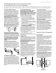
Application CommentsUse and Care Manual and installation instructions areshipped with Zoneline ® units. It is important that any <strong>air</strong>conditioning system be properly sized and applied in orderto achieve the desired temperature and humidity levels withthe space to be conditioned. Air <strong>conditioners</strong> are designedprimarily to provide heating and cooling with the additionalbenefit that during operation in the cooling mode, the unitsalso remove some moisture from the conditioned space.The following are some brief application comments onundersizing, oversizing, heating, wall coverings, and <strong>air</strong>infiltration: all are important in the proper matching of theheating/<strong>air</strong> conditioning system to the building structure.Undersizing: If an <strong>air</strong> conditioner is undersized (coolingcapacity is less than required for a specific application), theunit will typically not be able to cool the space down to thedesired temperature (thermostat set point), nor be able toremove enough moisture from the <strong>air</strong>. A result could be awarm and humid or warm and dry conditioned space.Oversizing: If an <strong>air</strong> conditioner is oversized (cooling capacityis greater than required for the specific application), the unitwill typically cool the space down to the desired temperature(thermostat set point) too quickly. The compressor thenbegins to cycle on and off. Dehumidification only takes placewhen the compressor is operating. A typical result in a hot/humid climate could be a cool but excessively humid space.Heating: Undersizing can result in not being able to maintainthe desired temperature level within the conditioned space.Wall Covering: Use of a non-permeable wall covering (somepaints, some wallpapers, and other types of coverings) whichseverely restricts passage of <strong>air</strong> or water vapor can cause asevere moisture problem. Typical results could be staining ofroom surfaces, wall damage, as well as mold and mildewgrowth in hot/humid climates.Air Infiltration: Excessive <strong>air</strong> infiltration can magnifyproblems associated with undersizing or oversizing of an<strong>air</strong> conditioner unit and can be the root cause of insufficientcooling, dehumidification, or heating. Some sources of <strong>air</strong>infiltration include vents, gaps around windows and doors,and improperly sealed floor, ceiling and wall joints.Recommendation: For the above reasons it is stronglyrecommended that a professional engineer be retainedto match the Zoneline unit with the building structure.Air DistributionZoneline <strong>packaged</strong> <strong>terminal</strong> <strong>air</strong> <strong>conditioners</strong> and heat pumpsdischarge <strong>air</strong> from the top of the unit through reversible2-position discharge louvers. Unit discharge louvers arereversed by removing the room cabinet from the unit,removing seven screws that hold the louver section inplace, removing the louver section and rotating it end forend, reinstalling the louver section in the room cabinet withthe seven screws, and reinstalling the room cabinet on theunit. The unit is shipped from the factory with the dischargelouvers at an angle of 50° off vertical. In the alternateposition, the louvers will be at an angle of 40° off vertical.All room cabinets return <strong>air</strong> through the front of the unit.High Wall Mount — For unitsmounted high in the wall, thedischarge louvers should beat a setting that provides themost horizontal <strong>air</strong> discharge.Recommended installation isat least 3" below the ceiling.In installations where unitsare close to the ceiling, themost horizontal dischargeangle can be obtained byremoving the discharge grillfrom the room cabinet.Supply Air Throw — OneZoneline unit should not berequired to do a job obviouslyrequiring two or more units.Units should be located aroundlarge rooms according tocalculated loads or in suchfashion as to achieve balanced<strong>air</strong> distribution in all parts ofthe room. The single unit inthe “Incorrect” illustrationbelow obviously cannotcondition the entire room.Add a second unit as shownin the “Correct” illustration.OVER 40 FT.CORRECTOVER 40 FT.50°40°INCORRECT20
Dimensionsge.comRAB71A WALL CASEA13-3/4"42"1/2" SQ. HOLE (2 REQ'D.)AdditionalWall Case DepthsRAB7116 - 16"RAB7124 - 24"RAB7128 - 28"RAB7131 - 31"2-3/4"16"1-1/2" TYP 1/2"5-5/8"4"WALL OPENING16-1/4" MIN. x 42-1/4" MIN.36"21"6"1/2" DIA.HOLE (3 REQ'D.)RAB77 WALL CASE42-1/8"13-7/8"2-7/8"16-1/4"1-1/2"1/2" SQ. HOLE(2 REQ'D.)9/16"5-5/8"4"WALL OPENING16-1/2" MIN. x 42-3/8" MIN.36"19"6"1/2" DIA.(3 REQ'D.)WALL CASE WITHCHASSIS INSTALLEDRAB71 = 42"RAB77 = 42-1/8"GRILLERAB71 = 20-7/8"RAB77 = 21"7-1/8"GRILLERAB71 = 13-3/4"RAB77 = 13-7/8"TOP VIEWSIDEVIEWRAB71 = 16"RAB77 = 16-1/4"INSIDEOUTSIDE42"ROOMCABINETROOMCABINETWALL CASE WITHSUB-BASEFRONT VIEW*SIDE VIEW13"3-1/2" 12-3/4" 12" 9-3/8" 2-1/2"1-7/16"KNOCKOUTS (ENCLOSURE)LEVELING SCREW4 REAR; 4 BOTTOMSEE PA<strong>GE</strong> 32 FOR KNOCKOUT LOCATION DIMENSIONS.3" MIN.ADJUSTABLETO 5" MAX.1-5/16"2-3/8" MIN.INTERIORWALLFINISHED FLOOR*SHOWN WITH ACCESS COVERS REMOVED.NOTE: CAUTION - REMOVE KNOCKOUTS FROM INSIDE OUT.Installation Instructions Packed With Wall Case . . . See Page 25 For Additional Information Concerning OutdoorWeather Panel and Case Stiffener.21
Wall CaseA choice of wall cases is available for the Zoneline. ®RAB71A — This insulated case is constructed of heavy-gaugegalvanized steel and finished with a protective baked-enamelfinish for protection and appearance. Design of the caseprovides for support of the chassis and free draining of anywater entering the wall case. A petroleum microcrystallinewax is applied at critical points of fabrication to seal againstmoisture. The dimensions of the RAB71 wall case are: 42"wide by 16" high by 13-3/4" deep, the same dimensions as theoriginal wall case for <strong>GE</strong> Zonelines built in 1961. The RAB71wall case is also available in depths other than the standarddepth. It is available on special order as: RAB7116 – 16" deep;RAB7124 – 24" deep; RAB7128 – 28" deep; and RAB7131 – 31"deep. All of these special-order deep wall cases are insulatedand have sheet metal dividers, or splitters, to prevent therecirculation of condenser discharge <strong>air</strong>.RAB77 — This non-insulated wall case is molded fromfiberglass-reinforced polyester compound. This SMC(Sheet-Molded Compound) wall case offers outstandingstrength, durability, color retention, water integrity andcorrosion resistance. The dimensions of the RAB77 wallcase are: 42-1/8" wide by 16-1/4" high by 13-7/8" deep.• Both wall cases are of universal design, accepting allZoneline chassis of current design as well as all <strong>GE</strong> Zonelinechassis produced since 1961.• Drain holes are provided in the rear of the wall case topermit excessive cooling condensate water, heat pumpcondensate or precipitation entering the wall case to drainfreely. A drain kit may be connected to the wall case tocontrol any water draining from the wall case. See page34 for information on RAD10 Drain Kit.RAK901L — For installations where the wall case extends intoroom, RAK901L is an insulation kit that can be used with theRAB77 or any existing non-insulated wall case to minimizethe possibility of condensation forming on the indoor side ofthe case during the winter.Sub-BaseThe sub-base is an optional accessory for the Zonelineand is presented with the wall case information since thedecision to use or not to use a sub-base in the installationis a factor in the location of the wall opening for the unit.National Electrical Code ® requires that <strong>air</strong> conditioning unitsconnected to voltages in excess of 250 volts be “permanentlyconnected.” There are also some installations where unitsconnected to voltage sources under 250 volts may alsoneed to be “permanently connected.” If you are in doubtabout the requirements for a particular installation, consultArticle 440 of the NEC or the local electrical inspector. Theserequirements are designed to protect personal safety andshould be strictly followed. Although NEC is cited here as areference, all electrical wiring and installations must conformto any and all local electrical codes and regulations.“Permanent Connection” generally means wiring to the unitmust be contained in an enclosed “chaseway,” where accessto the wiring connections is more restrictive than a normalline cord plugged into a receptacle. NEC requirements maybe met by using flexible or rigid conduit to contain the wiringbetween the unit and a junction box that contains the wiringconnections. The conduit is connected to the unit and to thejunction box with connectors to hold the conduit in place.The junction box may be located in the floor or the wall of thestructure but only approved connectors may be used outsidethe unit or the junction box. The sub-base is UL ® listed as ajunction box for permanent connection of a Zoneline.Using a sub-base in an installation requiring permanentconnection provides a convenient, consistent location forunit wiring to be connected to building wiring. The use ofa sub-base is not required, but the convenience and theimproved aesthetics it offers makes the use of a sub-basea viable means of permanent connection.RAK204U — The RAK204U Series of sub-bases provides avariety of designs that fit the site needs and are availablefor use with Zoneline PTAC/PTHP units. The RAK204U willmost likely be used for support of the wall case and unit.The RAK204U is the same physically as the other sub-basesexcept there is no receptacle installed. Receptacles andwiring can be field installed and, by using the RAK205CWchaseway and the RAK4002 junction box perform the samefunction as any of the other sub-base kits by selecting thecorrect receptacle and installing it in the interior mountingplate inside the RAK204U.208/230-volt receptacles can also be mounted in the coverplate for easy access when direct connect wiring is notrequired. 265-volt units are to be “Permanently (or Direct)Connected” and the external receptacle (when wiring is notenclosed in a chaseway) does not meet this requirement.A knockout for a fuseholder or a disconnect is also providedin the cover plate.RAK204U — No receptacle, no wiring, will accept any15-, 20-, 30-amp receptacle and wiring. No chaseway isincluded. RAK205CW chaseway must be ordered separately.The 230/208-volt sub-bases below include a short,sub-base power connection kit. Since sub-base connectedunits are not considered to be line-cord connected, aLeakage Current Detection and Interruption or Arc FaultCurrent Interrupter device is not necessary.The junction box (RAK4002A for 2800 and 3800 Seriesunits; RAK4002B for 5800 Series units) that mounts onthe chassis of 230/208-volt sub-base connected unitsmust be purchased separately.RAK204D15P 208/230-volt 15-amp receptacle. Receptacleis NEMA6-20R with 18" of #12AWG wires attached tothe receptacle. Short power connection kit included.Chaseway included.RAK204D20P 208/230-volt 20-amp receptacle. Receptacleis NEMA6-20R with 18" of #12AWG wires attached tothe receptacle. Short power connection kit included.Chaseway included.22
ge.comCord set connectedWALL SECTION – DETAILED SIDE VIEWFrame and Brick Veneer InstallationSub-Base ConnectedLINTEL2-3/8"CAULK*STEEL LINTELCAULK*CAULK*1/4"CAULK*RAB71 13-3/4"RAB77 13-7/8"RAB71 13-3/4"RAB77 13-7/8"20-7/8" (RAB71)21" (RAB77)20-7/8" (RAB71)21" (RAB77)MOUNTING SCREWSBY INSTALLERRAB71 16"RAB77 16-1/4"OUTDOORGRILLEMOUNTING SCREWSBY INSTALLERRAB71 16"RAB77 16-1/4"OUTDOORGRILLEROOMCABINET2" MIN.WALL CASEROOMCABINETWALL CASESIDE CHANNEL2" MIN.FINISHED FLOOROR TOP OFCARPETCAULK*WALL RECEPTACLE(BY OTHERS)*Caulk around perimeter of wall case all four sideswhere it joins the building - Interior and Exterior.CAULK*1/4"MIN.POWER SUPPLYCONDUITRAG60 1/4"RAG61, 62, 63 1-3/8"RAG64, 65, 66 1-3/8"3" MIN.5" MAX.FINISHED FLOOROR TOP OFCARPET1-5/16"SUB-BASE(RAK204)CAULK*3-11/16" *Caulk aroundperimeter of wallcase all four sideswhere it joins thebuilding - Interiorand Exterior.POWER SUPPLY CONDUIT(ALTERNATE ENTRY)27
Gasket andcaulk aroundperimeter ofwall case allfour sideswhere it joinsthe buildingOUTDOORGRILLEUSE NOSCREWS INBOTTOM OFCASEWALL SECTION – DETAILED SIDE VIEWWindow, 2" curtain or panel wall installation with rag rear grille extended beyond outer wall surfaceCord Set ConnectedSub-Base ConnectedWALL ORWINDOWCASE ANGLE (FIELD SUPPLIED)CASE ANGLE (FIELD SUPPLIED)RAB71 22-1/4"RAB77 22-3/8"WITH RAG61-66Gasket andcaulk aroundperimeter ofwall case allfour sideswhere it joinsthe buildingRAB71 22-1/4"RAB77 22-3/8"WITH RAG61-66RAB71 21-1/8"RAB77 21-1/4"WITH RAG60RAB7116"RAB7716-1/4"ROOMCABINET16"OUTDOORGRILLERAB71 21-1/8"RAB77 21-1/4"WITH RAG60RAB7116"RAB77A16-1/4"ROOMCABINETWALL CASEWALL CASERECEPTACLE(BY OTHERS)GASKET(FIELDSUPPLIED)SIDECHANNEL(RAK204)SUB-BASELEVELING LEGMIN. 2 SUPPORTSFIELD SUPPLIED FLOORFLOORPOWER SUPPLYCONDUIT(ALTERNATE ENTRY)16"3" MIN.5" MAX.28
ge.comFINISHEDEXTERIOR WALLCAULK*WALL CASE INSTALLATION – CORD SET CONNECTEDExample: block and veneer – dimensional data and commentsAre also applicable to other types of constructionCASERAB71 42"RAB77 42-1/8"CAULK*ADimensionAManufacturer RequiredMinimum Installation Clearance1/4" (See note 1)CAULK*RAB71 13-3/4"RAB77 13-7/8"CAULK*BCDEAllow For Electrical Wiring 0" Min. (See page 27)0" Minimum0" Minimum 2" RecommendedSee pages 38-39 for ducted application.3" MinimumCNOTE:1. FOR OUTSIDE FLUSH MOUNTING SEE PA<strong>GE</strong> 35 FOR DRAIN INSTALLATION.FINISHEDEXTERIORWALLDADJACENT WALL2-1/2"ROOM CABINET27-1/4"TOP VIEW*Caulk around perimeter of wall case all four sideswhere it joins the building - Interior and Exterior.DADJACENT WALLLINTELMAX. WALL THICKNESS13-1/8"SIDE VIEW OFALTERNATEHIGH MOUNTWith conduitpower supply.ECAULK*ACAULK*ROOM CABINETWALL OPENING16-1/4" x 42-1/4" MIN. FOR RAB7116-1/2" x 42-3/8" MIN. FOR RAB77INSIDEROOMCABINETRAB71 13-3/4"16" RAB7116-1/8" RAB777-1/8"RAB77 13-7/8"ELECTRICAL RECEPTACLE (BY OTHERS).FLUSH MOUNTED.FRONT VIEWBCAULK*CONDUITFIELDSUPPLIED*Caulk aroundperimeter of wall caseall four sides where itjoins the building -Interior and Exterior.See page 42 for line cord length.FINISH FLOOR29
METAL CASE EXTENSION FOR WALLS DEEPER THAN 13-1/8" (11-1/8" WITH SUB-BASE)Field fabricated – ge recommends the use of one of the deeper RAB71 wall cases offered as special order items.Zoneline units can be installed in walls of greaterdepth than the wall case. Where the case recession isless than 3" and where it is possible to waterproof theexposed sides and top of the opening, the suggestedprocedure is to apply a flashing to the bottom of thewall case as shown on page 31. Where waterproofingis questionable or not possible, or for installations inwalls of greater depth, the following is a suggestedapplication procedure. It involves the field fabrication ofa case extension. Since the wall case is a water bearingcontainer, the extension likewise must also be waterbearing and the connection between the two must bewatertight. The case extension must contain splitters toprevent recirculation of the outdoor <strong>air</strong> circuit.1. The case extension is field fabricated. The extensiondepth “D” should allow for a minimum outdoorprojection of 1/4". This allows for room cabinetclearance to the finished wall and ample surfacesto apply sealant or caulking for a tight weather sealbetween the completed wall case/extension assemblyand the wall opening. It is recommended that theextension be painted and corner and lap joints beadditionally sealed with a quality grade sealant.2. The wall case and extension should be connectedprior to installation in the wall opening. A qualitygrade sealant should be applied to all four (4) buttingflanges. Use bolts and nuts or oversized self tappingscrews (driven from the wall case to the extension)to attach the two assemblies. Clean all drain holes ofexcess sealant. The assembly must be free draining.3. Install flashing, using a quality grade sealant betweenthe flashing and wall as shown in section A-A below.4. Install the wall case/extension assembly followingprocedures described for a standard installation.See diagrams below. The assembly should be sealedor caulked to the wall around all four sides bothoutdoors and indoors.NOTE: The wall case/extension assembly shouldbe level.SEALANT - ALLFOUR (4) FLAN<strong>GE</strong>S6-1/4" ± 1/4" AS REQ'D.D5. Suggested materials for case extension and flashingshould be non-ferrous metals. Minimal acceptablematerial: Galvanized G-90 painted.CAULK*ROOMCABINETWALL -ANYCONSTRUCTIONRAB71/77CASEEXT.1/4" MIN.CAULK*CAULK*CAULK*SPLITTER BETWEENAIR INTAKE ANDDISCHAR<strong>GE</strong>*Caulk around perimeter of wall case all four sideswhere it joins the building - Interior and Exterior.10-5/8" ± 1/4"SECTION A-ABASEPAN/FLAN<strong>GE</strong> DESIGNSHOWING SEALANT LOCATIONS.SEE DETAILSECTION A-ARAB71/77WALL CASE1-1/2"(4 SIDES)EXTENSION(FIELDSUPPLIED)CUT DRAIN SLOTSIN BOTH FLAN<strong>GE</strong>S(FOUR REQUIRED)TO MATCH DRAINHOLES IN RAB71/77ALL 4SIDESWALL CASEALL 4 FLAN<strong>GE</strong>SFLASHIN<strong>GE</strong>XTENSIONALL 4SIDES2" MIN.FLASHING (FIELD SUPPLIED)13-3/4" + D"1" WIDE45° DRIP LIPFLAN<strong>GE</strong>S ANDDRAIN HOLELOCATIONSSAME AS ONWALL CASEWALL30
ge.comALTERNATE – CASE RECESSION LESS THAN 3" WITH SIDES AND TOP OF WALL OPENING WATERPROOF, FLASHING ON BOTTOM ONLYFor an installation that willprovide better protectionagainst water infiltration,<strong>GE</strong> recommends the useof one of the deeper RAB71wall cases offered asspecial order items.See page 23.DABBCOUTDOORGRILLECASEFLASHINGCAULK*A1" WIDE 45° DRIP LIPDIMENSIONS:A. DISTANCE FROM GRILLE OR CASE TO OUTSIDE SURFACE OF WALL PLUS 2" TO 4"(TO INSERT UNDER CASE).B. 1" DRIP LIP (MINIMUM)C. 42" PLUS - SUFFICIENT TO FIT SNUGGLY UNDER AND UP AROUND THE CASE.D. 2" MINIMUM(CAUTION: WHEN CAULKING DO NOT BLOCK DRAIN HOLES IN CASE OR GRILLE.)IF GRILLE IS TO BE MOUNTED TO WALL SURFACE A SPLITTERS MUST BE USED, SEE PA<strong>GE</strong> 30.*Caulk around perimeter of wall case all four sideswhere it joins the building - Interior and Exterior.31
RAB71/77 WALL CASE INSTALLATION - RAK204 SERIES SUB-BASE CONNECTEDExample: frame & brick veneer - dimensional data and commentsAre also applicable to other types of constructionDimensionAManufacturer RequiredMinimum Installation Clearance1/4" (See note 1)2-3/8"MIN.TOP VIEWLEVELING SCREW LEVELING SCREWRAB71 13-3/4"RAB77 13-7/8"BCD3" Min. (5" MAX.)2-3/8" Minimum0" Minimum 2" RecommendedSee pages 38-39 for ducted application.FINISHEDINTERIORWALLNOTE:1. FOR OUTSIDE FLUSH MOUNTING SEE PA<strong>GE</strong> 31 FORFLASHING INSTALLATION.5.15" 7.70" 18.86" 1.5"5.15" 7.70"RECOMMEND 2" TOINTERIOR ADJACENTWALL BOTH SIDES.BACK VIEW8.80"10.30"3" MIN.ADJUSTABLETO 5"SIDE VIEWWITH WALLCASE SHOWNIN PLACE1-5/16" 2-3/8"1-1/2"INTERIORWALL7/8"RAB71 16"RAB77 16-1/4"FINISHED FLOORMOUNTING SCREWSAND HOLES BYINSTALLERCAULK*CMAX. WALL THICKNESS11-1/8"A*Caulk aroundperimeter ofwall case allfour sideswhere it joinsthe building- Interior andExterior.D 42"D13-3/4"FRONT VIEWSEE NOTELEFT SIDERAB71 16"RAB77 16-1/4"ROOMCABINET3-11/16"2-3/8" MIN. CASEED<strong>GE</strong> TO FINISHEDWALLINTERIORADJACENTWALL12-3/4" 12-7/8" 13"FINISHED FLOORB CAULK*CAULK*KNOCKOUTS(ENCLOSURE)4 REAR; 4 BOTTOM*SHOWN WITH ACCESS COVERS REMOVED.NOTE: CAUTION - REMOVE KNOCKOUTS FROM INSIDE OUT.KNOCKOUT SIZELAR<strong>GE</strong> 1-1/8" DIA.SMALL 7/8" DIA.LEVELING SCREWLEVELING SCREWS(2) SUB-BASE BODY(2) SIDE EXTENSIONSCONDUIT ENTRY(ALTERNATES)SIDE VIEW32
ge.comRAK204 SERIES SUB-BASE INSTALLATION AND ELECTRICAL DATARAB71/77 Wall CaseCHASEWAY OPTION(Shown Without Chassis and Wall Case for Installation Location Only.)RAK4002BNOTE: TYPE “E”MOUNTING CLIP MUSTBE USED WITH MOLDEDCASE. MOLDEDCASE6"5/32" DIA. HOLE (SEE NOTE)FOR SECURING TYPE “D”CLIPS TO SLEEVE USINGTYPE “A” SCREWS6"GREENGROUNDSCREW(TYPE “C”)METAL CASETYPE “B” SCREWSCREW CLIPTYPE “D”TYPE “A”SCREWSUB-BASEMOUNTING CLIPTYPE “E”TO SECURESIDE CHANNELSTYPE “A”SCREWSIDE CHANNELS ARE ADJUSTABLEFROM 13-3/4" TO 2-3/8" IN LENGTHBY BREAKING OFF SECTIONS OF SIDECHANNELS.TYPE “C”SCREWACCESS PLATESTYPE “C”SCREWNOTE: IF METAL CASE DOES NOT HAVE SCREW HOLES, 5/32" DIA. HOLES MUSTBE DRILLED 6" FROM EACH SIDE IN FRONT FLAN<strong>GE</strong>. (SEE INSERT).TYPE “A” TYPE “B” TYPE “C”6 REQ’D. 2 REQ’D. 8 REQ’D.TYPE“D”TYPE“E”USE WITHRAB71USE WITHRAB77Electrical wiring may enter the sub-base through any of the knockout holes provided in the sub-base.Knockout holes in the sub-base access plate may accommodate a receptacle, which allows the use of a power cord (if permitted by code for the particular installation).A knockout for a circuit breaker, fuseholder or a disconnect is also provided. See pages 22 and 23 for description of electrical contents of these sub-bases.33
Condensate Disposal SystemsCooling CondensateAir <strong>conditioners</strong> produce condensate water as a result oflowering the humidity of the area being conditioned. Whenthe indoor coil temperature is below the dew point, moisturein the <strong>air</strong> condenses into water droplets on the coil. This waterdrains to a pan located under the indoor coil and is routedthrough the barrier, the partition separating the indoor andoutdoor sides of the unit, to the base pan on the outdoor side.It is then picked up and dispersed against the outdoor coil,which is hot when the unit is in the <strong>air</strong> conditioning mode.The water is evaporated into the atmosphere by contactwith the hot outdoor coil. This evaporation process also helpslower the temperature of the outdoor coil and improves theoperating efficiency of the unit.Slinger Ring SystemsPackaged Terminal units employ various means of dispersingthe condensate water against the outdoor coil. One of the mostpopular, and most effective, means is by the use of a “slingerring.” A “slinger ring” is a ring around the circumference ofthe outdoor fan. The design of the unit positions the slingerring very close to the bottom of the base pan so water inthe base pan is lifted by the rotating ring. Water picked upby the slinger ring will be dispersed into the <strong>air</strong> stream anddeposited on the hot outdoor coil where it evaporates.All Zoneline Series Packaged Terminal Air Conditionersand Packaged Terminal Heat Pumps utilize a slinger ringfor cooling condensate disposal.Certification Test RequirementsARI (Air Conditioning & Refrigerating Institute) requires that allcertified Packaged Terminal Air Conditioners and PackagedTerminal Heat Pumps pass a cooling condensate disposaltest. One stipulation of the ARI test is that “the test start withcondensate collection pan brimful.” In order to pass the ARICondensate Disposal Test the unit must operate continuouslyfor four hours without condensed water blowing, dripping,or running off the unit casing during the test or after theunit has been turned off. Under extremely high outdoorhumidity conditions or extreme operating conditions, suchas exceptionally high <strong>air</strong> infiltration (a door or window leftopen while the unit is running, for instance) it is possible forany <strong>air</strong> conditioner to be unable to dissipate all the coolingcondensate generated.All Zoneline ® Series Packaged Terminal Air Conditionersand Packaged Terminal Heat Pumps meet the condensatedisposal requirements of ARI standards 310-93 and 380-93.Heat Pump CondensateDuring the operation of a unit in the heat pump, or “reversecycle,” mode the outdoor coil becomes the cold coil and theindoor coil becomes the hot coil due to reversing the flow ofthe refrigerant. When the temperature of the outdoor coil isbelow the dew point, condensation will form on the outdoorcoil just as it does on the indoor coil during cooling operation.Since the dew point is humidity- as well as temperaturerelated,there may be more condensate on days when therelative humidity is high.34Heat Pump Condensate DisposalSince the outdoor coil is cold during heat pump operation, thecondensate water cannot be deposited on the outdoor coilas the water would cause frost to form on the coil. This frostwould block the <strong>air</strong>flow through the coil and greatly reduce theoutdoor <strong>air</strong>. Rather than allow this problem to occur, heat pumpunits must dispose of the condensate in another manner.Temperature-Activated Drain ValveThe most widely used method ofdisposing of heat pump condensateis with a “Temperature-ActivatedDrain Valve.” This is a device mountedin the base pan of a heat pumpunit with a bellows that expands ontemperature rise and contracts withtemperature drop. A shaft with arubber plug on the end is connectedto the bellows. When the outdoortemperature remains above a certain temperature, thebellows is expanded and the plug fits tightly into a holein the bottom, or base pan, of the unit. When the plug isblocking the hole, as it should be during cooling operation,the condensate water is contained in the base pan. Attemperatures when heating is required, the bellowscontracts, the rubber plug is retracted from the hole andthe heat pump condensate water is allowed to drain intothe wall case. The valve is fully open at 49°F.Drain KitsAlthough the Zoneline units are designed to dissipate all ofthe condensate generated during normal cooling operation,there may be times when abnormal operating conditionscause more condensate than the unit can dissipate. Heatpumps also generate condensate that the unit may notbe designed to dissipate. For these reasons, if condensatedripping from the wall case is objectionable, an internal orexternal drain system should be installed. See pages 35 and36 for information covering the drain systems and the RAD10kit available to connect to the wall case.Internal Condensate Removal (ICR) System<strong>GE</strong> has developed an Internal Condensate Removal (ICR)System for Packaged Terminal Heat Pumps. This system hasbeen offered as an option on Zoneline Packaged TerminalHeat Pumps since 1982, and thousands of them are in use.During heat pump operation the ICR system utilizes a smallpump to lift the water from the base pan and pump it intoa collector tray positioned above the indoor coil. The waterdrains from the collector tray and drips onto the warm indoorcoil where it is evaporated into the room atmosphere. If anexcess amount of water is pumped to the indoor side, it isrouted back to the outdoor portion of the base pan.The ICR system has proven to be an effective means ofminimizing the amount of heat pump condensate drippingfrom the unit. However, if the restrictions of a particularinstallation will allow absolutely no drippage of condensatewater from the wall case, the installation of an internal orexternal drain system is recommended.Units with ICR may not be installed in seacoast or corrosiveenvironment applications.
ge.comWALL CASE WITH RAD10 DRAIN KITExternal Drain. See page 36 for internal drain.SCREWS“A”METAL“B”PLASTICSEE PA<strong>GE</strong> 36 NOTE #6SQUARE DRAIN HOLES1/2" O.D. 90° ELBOW DRAIN TUBENEOPRENE SPON<strong>GE</strong> GASKETUSE TYPE “A” SCREW FOR METAL CASE (RAB71)AND TYPE “B” SCREW FOR MOLDED CASE (RAB77)STEEL MOUNTING PLATECaulk aroundperimeter ofwall case allfour sideswhere it joinsthe building.WATER DRAINA<strong>GE</strong> - Precipitation entering the unit through the outdoor louver may not be removed entirely by thecondensate removal system. The base pan flange is designed to allow excess water, either condensate water orprecipitation, to flow into the wall case and drain through two drain holes in the rear of the wall case. If there is morewater in the wall case than can be drained through these holes it will drain through the three overflow drain holes.These drain holes must not be blocked when mounting or caulking the wall case.For those installations where water draining from the drain holes is objectionable or where positive drainage is desired,the RAD10 drain kit is available with either a 90° elbow or a 6" straight tube to be used either to connect to a field supplieddrain line or to allow the water to drip free rather than drain down the surface of the building.NOTE: Drain kit using either the 90° elbow tube or the straight tube may be installed without modification when usingRAG60 exterior grille. Drain kit using the 90° elbow tube may be installed without modification when using RAG61through RAG66 exterior grilles. Modification must be made to the RAG61 through RAG66 exterior grilles when using thestraight tube. Modification must be made to the RAG67 grille if using either the 90° elbow tube or the straight tube (seeinstallation instructions with the RAG67 grille).REARGRILLE90° ELBOWDRAIN TUBEPROJECTIONBEYOND WALLCASE3"4"Alternate6" long, 1/2"O.D. straightcopper tube.NOTE: SHADED PARTS ANDSCREWS ARE INCLUDEDWITH RAD10 DRAINKIT. USE EITHER THE90° ELBOW TUBE ORTHE STRAIGHT TUBEDEPENDING UPONTHE REQUIREMENTSOF THE PARTICULARINSTALLATION.TYPICAL INSTALLATIONCASE ANGLES (FIELD SUPPLIED)WALL CASE ROOMCABINETMIN. 2 SUPPORTSFIELD SUPPLIEDFLOOR35
WALL CASE WITH RAD10 DRAIN KITInternal Drain. See page 35 for external drain.NOTE: SHADED PARTS AND SCREWSINCLUDED WITH RAD10 DRAINKIT. THE 90° ELBOW TUBE ISRECOMMENDED FOR INTERNALDRAIN INSTALLATION.SCREWSSEE DETAILBELOW“A”METAL“B”PLASTICOVERFLOW RELIEF DRAINSEE NOTE 6SQUARE DRAIN HOLESNEOPRENE SPON<strong>GE</strong> GASKETSTEEL MOUNTING PLATENUT(MOLDED CASE (RAB77) ONLY)DETAILUSE TYPE “A” SCREW FOR METAL CASE (RAB71)AND TYPE “B” SCREW FOR MOLDED CASE (RAB77)GASKETTUBE1/2" ODCOVERPLATECABINET BOTTOM1. The RAD10 drain kit is installed in the bottom of the wall case when it is desired to draincondensate to an internal drain system in the building.2. The drain kit is mounted on the bottom of the wall case prior to installation of the case in thewall. It may be located anywhere on the room side portion except for sub-base installations.For these the drain should be at least 3" from the indoor edge of the case so as to adequatelyclear the sub-base.3. A template is furnished with the kit for locating the necessary 3 holes in the case bottom - twoto provide a securing means and one to provide a drain hole for the 1/2" od tubing.(See details at left)4. A tube or hose 1/2" I.D. (Obtained locally) must be installed on the drain tube and connectedto the internal drain system in the building.5. With the RAD10 the two square drain holes in the bottom outer flange of the wall case aresealed by the gaskets and mounting plates shown above.6. Three (3) 1/2" diameter holes located 1/4" above the case bottom in the bottom outer flangeprovide overflow drainage to the outdoors when wind driven rain enters the chassis.USE TYPE “A” SCREWS FOR BOTH RAB71 AND RAB7736
Ducted Installations2800 and 3800 Series Zoneline units may be usedin ducted installations.With a ducted installation it is possible to condition the<strong>air</strong> in two areas that have a common wall separatingthem. A special adapter mounts on the wall case and atransition piece directs the <strong>air</strong> from the unit into theadapter. Instructions for mounting the adapter to the wallcase are included with the duct adapter. The adaptercontains agrille that allows <strong>air</strong> from the unit to be discharged into theprimary room and the adapter connects to a duct extensionthat allows the <strong>air</strong> to flow to the adjoining room. Ductinga unit may allow a single unit to be used rather than aseparate unit in each room, providing a means of reducinginitial equipment cost. The duct may extend a total of 15feet (with a field fabricated insulated duct extension) in onedirection, either to the right or to the left of the unit. A bafflein the adapter allows up to 50% of the discharge <strong>air</strong> to bedelivered to the secondary room.The installation of the wall case and sub-base, if used, is thesame for units being ducted as for free-standing units. Theduct adapter support bracket overlaps the wall case by 1"and the bracket and mounting screws add approximately3/8" (3/16" on each side) to the width of the wall case. Ifless than 1" of the wall case projects into the room it willbe necessary to allow for the additional width in theopening for the wall case. The duct adapter mountingbrackets should be mounted prior to installing the case inthe wall.Refer to pages 38 and 39 for drawings of ductedinstallations.Prior to the installation of the transition from the roomcabinet to the adapter, it will be necessary to remove thedischarge grille from the room cabinet. Instructions for thismodification are included with the duct adapter.New Ducted InstallationsDuct Adapter RAK6052ComponentsDuct Adapter RAK6052 — The duct adapter is securedto each side of the wall case and requires the drilling ofmounting holes in the wall case during installation. Atemplate for the hole location is in the installationinstructions. By securing the duct adapter to the wall case,the chassis retains the slide-out feature for servicing afterthe transition piece is removed.Duct Extension RAK601 — This kit contains a 44"-longinsulated duct, a register mounting collar, and an <strong>air</strong> supplyregister. It can be secured to the duct adapter at either endof the adapter. This duct may be cut at any dimension andused in two applications providing the sum of the two ductlengths necessary do not exceed the 44" length. Even insingle applications the mounting flange must be cut offge.comRAK601 DuctExtension,Mounting Collarand Registerone end of the duct to accept the collar and supply register.Mounting Collar and Supply Register RAK602 —Thesecomponents are included in the Duct Extension Kit RAK601.They may be ordered separately for installations where twoduct extensions are made from one RAK601.Ducted Application ConsiderationsWhen designing a ducted application some applicationconsiderations to be made include:1. Do not exceed the 15-foot length maximum for theduct extension. Field supplied duct extension must becompletely insulated with minimum of 1/2" insulation2. The duct must be a straight run. Turns or bends in theduct extension create <strong>air</strong> pressure drops that the unit isnot designed to overcome.3. Minimum recommended clearance between the unit andthe adjacent wall is 2".4. Provisions for return <strong>air</strong> must be made to allow <strong>air</strong>circulation from secondary room. Doors in both secondaryand primary rooms may be undercut or a return grillemay be installed through a common wall.5. When calculating the heat gain/heat loss take both areasinto consideration.Replacements of Existing Ducted UnitsSince the design of the Zoneline chassis has changed overthe years to provide better performance and appearance,some of the components used in ducted applications havechanged. Select the proper components from the informationbelow. The best procedure in determining the correct kit is tomeasure duct extension cross section.Flat Top-Discharge Units (Zoneline Units Built Priorto 1988)Existing Duct Extension Cross Section Measurements:8-3/8" height x 6-1/2" widthDuct Adapter RAK7012 — This duct adapter will allow thereplacement of a new chassis (2800 or 3800 Series unit)into an existing ducted application. This adapter will alignproperly with the duct extension and will eliminate the needto modify the wall opening. In order to minimize replacementcosts, some of the components of the old duct adapter mustbe removed and used in the new installation. Consult theInstallation Instructions of the RAK7012 before removing anddiscarding the old duct adapter. See additional notes page 58.Slope-Front Discharge Units(Models With AZC, AZR, AZW, or AZ21 or AZ31 Prefix)Existing Duct Extension Cross Section Measurements:7-3/32" height x 6-1/2" widthDuct Transition RAK7022 — This duct transition will allow thereplacement of a new slope-front discharge Zoneline chassis(2800 or 3800 Series unit) into a previous design slope-frontducted installation. See additional notes page 58.37
DUCTED APPLICATION (AZ2800/3800 SERIES)44"RAK60144" LENGTHRAK6052ADAPTERTRANSITIONNotes:1. RAK6052 kit includes duct adapter, transition and mounting hardware.2. RAK601 duct extension may be installed at either end of the RAK6052 duct adapter.Maximum duct extension length is 15'. Duct extension must be field fabricated forinstallations where length of duct exceeds length of RAK601 (44"). Field fabricatedduct extension must be insulated to prevent condensation from forming on exterior.Duct extension may not contain bends or turns.3. Ducted units may need to be permanently connected. Check local code for specificelectrical installation requirements.4. Duct extension kit RAK601 contains 44" duct extension, discharge grille mountingcollar, and discharge grille. Duct extension must be cut to required length. Two ductedinstallations may be made from one kit if the combined ducted length is less than 44".RAK602 kit contains mounting collar, discharge grille and mounting hardwarenecessary for second installation.5. Filler strip (field supplied) actual width depends upon wall case projection into room.A flush installation to finished wall (I.E., No filler strip) can be made.6. Unit must be installed to provide at least a 2" clearance between side of unit and wall.7. Provisions for return <strong>air</strong> must be made in order to allow <strong>air</strong> circulation from secondaryroom. Doors in both secondary and primary rooms may be undercut or a return grillemay be installed through common wall.8. For replacement of previous design units, see pages 37 and 58.8" highDUCT ADAPTER EXTENSION HAS 1/2" INSULATION7-3/8"wideRECOMMENDEDMINIMUMCLEARANCE2" TO SIDE WALL38
ge.comLine Cord InstallationDUCTED DETAILED SIDE VIEWS (AZ2800/3800 SERIES)See page 38 for all notesSub-Base Installation6-1/2"ANY CONSTRUCTION12-3/4"MAX.2-3/8"*MIN.6-1/2" 11-1/8"MAX.10" 7-3/32"RAK6052ADAPTER7-3/32" RAK6052ADAPTER2-29/32"16-1/8"TRANSITIONROOMCABINET3/4" MIN.WALL TOCASE ED<strong>GE</strong>WALL CASE1/4"MIN.2-29/32"16-1/8"TRANSITIONROOMCABINETWALL CASEFINISHEDFLOORRECEPTACLE CAULK*(BY OTHERSALT. LOCATIONS) CAULK*FINISHEDFLOOR3" MIN.5" MAX.RAK204RAG60 - 1/4"RAG61-66 - 1-3/8"3-11/16"*Caulk around perimeter of wall case all four sideswhere it joins the building - Interior and Exterior.*2-3/8" min. when installed with RAK204.1/4"Caulk aroundperimeter ofwall case allfour sideswhere it joinsthe building- Interior andExterior.RAG60 - 1/4"RAG61-66 - 1-3/8"FILLER STRIP (SEE NOTE 5 ON PA<strong>GE</strong> 36)39
Exterior GrillesFour styles of outdoor grilles are available for exteriortreatments. The standard stamped aluminum grille (RAG60),the molded architectural louvered exterior grilles (RAG61-63),the molded architectural louvered exterior grilles with flange(RAG64-66), and the extruded aluminum architecturallouvered grille (RAG67). All grilles include <strong>air</strong> deflectorsand gaskets to prevent condenser <strong>air</strong> recirculation.RAG67RAG60Outdoor GrilleRAG60 Outdoor Grille — The standard exterior grille is madeof durable aluminum to protect chassis components andprevent <strong>air</strong> recirculation.RAG61Outdoor GrilleRAG61, 62, 63 Architectural Grille — One-piece optionalmolded grille and frame assembly provides improvedappearance, protection and weatherability. Molded ofdurable polycarbonate, the surfaces of the grille have acolorfast, slightly textured finish which blends well withmost types of wall surfaces. The grilles can be painted inthe field to match the building for improved aesthetics.RAG67 Extruded Aluminum Grille — The RAG67 is made fromextruded anodized aluminum for use where an aluminumarchitectural grille is preferred. The RAG67 is available in aclear finish and may be special ordered from <strong>GE</strong> in othercolors. Minimum order quantities may be required. Contactyour General Electric salesperson for details.All grilles are installed and secured to the wall case from theinside. Keyhole slots in the rear flange of the case allow thegrille to be placed in position before securing it firmly to thewall case.Replacement of existing units: If an existing grille is notreplaced, capacity and efficiency will be reduced and theunit may fail to operate properly or fail prematurely. Adeflector kit, RAK40, may be used with grilles that werenot designed for current AZ Series <strong>GE</strong> Zoneline units. TheRAK40 contains <strong>air</strong> deflectors and gaskets that mount tothe chassis to direct the hot exhaust <strong>air</strong> away from the <strong>air</strong>intake to allow the unit to function properly. All grilles usedwith <strong>GE</strong> Zoneline ® units must comply with requirementsof Exterior Architectural Treatments and Special OutdoorGrilles as follows.RAG64Outdoor GrilleRAG64, 65, 66 Architectural Grille with Flange — Identical toRAG61-63 grilles with the addition of a 1/2" flange around thetop and sides to help conceal the juncture of the RAB71 wallcase and the wall opening. The best appearance is achievedwith this grille when the wall case extends minimally (between1/4" and 1/2") beyond the exterior face of the building.Colors: RAG61 and 64 — Beige; RAG62 and 65 — Dark MapleRAG63 and 66 — Bittersweet Chocolate.40
Exterior Architectural Treatmentsand Special Outdoor Grillesge.comThe architectural design of a building may dictate the useof special or oversized louvers for aesthetic reasons. Louversother than standard Zoneline exterior grilles may be usedon the Zoneline unit, however, these special louvers, or anyspecial exterior architectural treatments of the buildingfacade that may restrict the free circulation of condenser<strong>air</strong>flow, should be referred to <strong>GE</strong> Application Engineering forevaluation and approval. The following guidelines should befollowed in selecting a louver:1. The louver must have a minimum of 65% free area.ASHRAE defines free area as the minimum area of theopening in an <strong>air</strong> inlet or outlet through which <strong>air</strong> canpass. Percent (%) free area equals the X dimension dividedby the Y dimension.2. The louver should be attached to the wall case in a mannerthat will prevent recirculation of condenser discharge <strong>air</strong>into the <strong>air</strong> inlet. If the louver is not attached directly tothe wall case, a field supplied splitter or gasket is requiredbetween the chassis and the louver to prevent recirculation.It is important that the above criteria be followed sincea louver that is too restrictive or allows recirculation willreduce the unit’s capacity and efficiency, increase theelectrical current draw, cause intermittent operation due tothe compressor overload protector shutting the compressoroff, and cause failure of the compressor overload andshorten compressor life. Using the unit with a grille thatis too restrictive or allows recirculation may constituteimproper installation. A scale drawing of the louver sectionshould be sent to <strong>GE</strong> Application Engineering. To assure theproper performance of the Zoneline unit and comply withUnderwriters Laboratories requirements, it may be necessaryto send a sample louver section (at least 16" x 42") to <strong>GE</strong> to betested with the Zoneline unit.Sample CalculationsFree Area (%) = x x 100 x = 1" y = 1.5"yF.A. % = 11.5x 100 = 66.7%41
Power Connection for 2800, 3800and 5800 Series ZonelinesAll 2800, 3800, and 5800 Series Zonelines are equipped withuniversal heaters allowing chassis installation flexibility. TheZoneline ® units are connected to the building power supplyby a unique power connection kit. By utilizing a separateuniversal power connection (UPC) kit, each unit is capable ofproviding various outputs of electric resistance heat to moreclosely meet the heating requirements of the particular room,thereby increasing the installation flexibility of the particularchassis. This power connection kit is the only means ofsupplying power to the Zoneline chassis. The appropriatekit is determined by the voltage, the means of electricalconnection, either line cord connected or permanentlyconnected, and the desired resistance heat output thatmay be supported by the branch circuit.230/208-Volt Line-Cord Connected UnitsLine Cord Kits consist of a self-aligning nine-pin moldedconnector that plugs into a mating connector on the Zonelinechassis and insulated line cord with an electrical plug onthe end. The configuration of the electrical plug conformsto NEC standards for the circuit amperage and the positionof the wires in the nine-pin connector determines the heaterwattage and current requirements when it is plugged intothe Zoneline chassis.The power connection kit is selected by the amperage ofthe circuit where it will be installed. Each line cord kit has anintegral Leakage Current Detection and Interruption (LCDI) orArc Fault Current Interrupter (AFCI) device as required by theNational Electrical Code (NEC) and Underwriters Laboratory(UL) for line-cord connected <strong>air</strong> <strong>conditioners</strong> manufacturedon or after August 1, 2004. The line-cord power connectionkits are shown in the table below.230/208-Volt Line-Cord Connected UnitsLine CordKitElectricHeatBTUHElectricHeaterWattsElectricHeatAmpsMin. CircuitProtection(Amps)RAK3153 8600/7100 2550/2090 11.6/10.6 15RAK3203 11700/9600 3450/2820 15.5/14.1 20RAK3303 17000/13900 5000/4090 22.3/20.3 30Electric Heat Amps include electric heater and fan motor current draw.230/208-Volt — Permanently Connected UnitsPermanently connected units do not require the LCDI or AFCIdevice. Permanent connection is usually made through theuse of a sub-base. Each 230/208-volt sub-base consists ofa sub-base with appropriate receptacle for minimum circuitamperage, a chaseway to route power connector from thesub-base to the chassis, wiring to connect the sub-baseto building wiring and a short-line cord with a self-aligningnine-pin connector to connect to chassis and plug into thereceptacle in the sub-base. Permanent, or direct wired,installation of a 230/208-volt unit requires a junction box kit,RAK4002A, which attaches to the chassis to form an enclosedjunction box.The short sub-base line cord may not be used without thesub-base.For 2800 and 3800 Series 230/208-volt units where apermanent installation using flexible conduit is desired, theRAK4002A forms an enclosed junction box on the chassis.The RAK4002A has a 7/8" diameter hole to allow conduit tobe connected to the junction box. A line cord kit, shown aboveunder Line-Cord Connected units, must be purchased andmodified to allow direct connection to the building wiring.The line cord kit should be cut about 8" from the nine-pinconnector. Strip insulation off 5/8" of each conductor toexpose wires for field connection. These wires are thenconnected to the building wiring by field-supplied connectors.For 5800 Series 230/208-volt units, the permanent installationusing flexible conduit procedure is the same as for the 2800and 3800 Series units, except the junction box kit is RAK4002B.230/208 Volt Sub-Base and Direct Connected UnitsSub-Base265 Volt Sub-Base and Direct Connected UnitsSub-BaseDirectConnectionKitPowerConnectionKitElectricHeatBTUHDirectConnectionKitElectricHeaterWattsElectricHeatBTUHElectricHeaterWattsElectricHeatAmpsElectricHeatAmpsRAK204E15 RAK5172 RAK5157 8600 2550 9.6 15RAK204E20 RAK5202 RAK5207 11700 3450 13.0 20RAK204E30 RAK5302 RAK5307 17000 5000 18.9 30Electric Heat Amps include electric heater and fan motor current draw.Each 265-volt sub-base kit consists of a sub-base with appropriate receptacle for minimum circuitamperage, a chaseway to route the power connector from the sub-base to the chassis and wiringto connect the sub-base to the building wiring.The 265-volt power connection kit must be ordered separately.All wiring must conform to local electrical regulationsand codes.Min. CircuitProtection(Amps)RAK204D15P RAK4157 8600/7100 2550/2090 11.6/10.6 15RAK204D20P RAK4207 11700/9600 3450/2820 15.5/14.1 20RAK204D30P RAK4307 170100/13900 5000/4090 22.3/20.3 30Electric Heat Amps include electric heater and fan motor current draw.265- or 277-Volt Unit Installation — PermanentlyConnected UnitsNational Electric Code (Article 440 Section G) requirespermanent connection for units connected to power sourcesover 250 volts; therefore these units must be permanentlyconnected (direct wired) with field-supplied connectors.Units connected using a sub-base meet the requirementfor permanent connection since all wiring is internal wiringbetween the sub-base and the chassis.Since 265-volt units may not be line cord connected, an LCDIdevice is not required.Min. CircuitProtection(Amps)42
Essential Elements Ordering Overview230/208-volt line-cord connected units — order line cord kit.230/208-volt sub-base connected units — order sub-base(includes power connection kit) and junction box for chassis.265-volt units — order sub-base and power connectionkit separately.Electrical Wiring Information –2800/3800/5800 SeriesAll Zonelines are single-phase 60 hertz units.For all installations, the feeder, sub-feeder, branch circuit andelectrical protective devices and selection must conform tothe National Electrical Code and to local codes.Maximum connected load in amperes, including demandsfor the electric heater and the fan motor, are shown on page44. Branch circuit ampacity and electrical protective devicesizing are shown on page 42 for 230/208-volt units and onthis page for 265-volt units.More than one unit per branch circuit is not recommended.When in doubt, consult the National Electrical Code. Allwiring, including installation of receptacle, must conformto local electrical regulations and codes.ge.comPermanent Connected Units With Sub-BaseIf the existing unit is connected to a sub-base the installationof the new unit may involve modifying the existing installationslightly. It is recommended these modifications be made by aqualified electrician.If the existing sub-base is the full width of the wall case,RAK201 sub-base access plate may be ordered and usedto replace the cover on the old sub-base. Field-suppliedwiring, conduit and conduit connectors should be used tomake a connection between the new chassis and the centerknockout of the RAK201. The wiring connections should bemade inside the sub-base and the RAK201 attached to thesub-base with the two screws provided.If the existing sub-base is not the full width of the wall case,the electrician will have to modify the existing cover plate toallow field-supplied wiring, conduit and conduit connectors tobe run from the permanent connection kit to the sub-base.Replacement of Existing Chassis230/208-Volt and 265-Volt UnitsThere have been changes to NEC and improvements andmodifications to the Zoneline chassis and sub-bases sincethe unit was first introduced. Some of these changes requirealterations to be made when replacing an older unit with anew chassis.Line-Cord Connected UnitsThe plug configuration of new line cord connected unitscomplies with the current NEC standards. Older installationsmay have wall receptacles that conformed to NEC standardsat the time the building was constructed and may not matchthe configuration of the plug on the new line cord. Therecommended solution is to change the wall receptacle toconform to current standard plug configuration. See charton this page for current receptacle configuration.Enclosure cover removed.RAK4002AWiring harness can be ordered separately as RAK4002CW.ReceptacleType Mfg Part No Configuration15 AMPTandemNEMA6-15RHubbellP&S5661566121"58"20 AMPPerpendicularNEMA6-20RHubbellP&S54615871Typical Line CordPower Connection KitRAK3203 shownInsideMaximum Cord Extension30 AMPLarge TandemNEMA6-30RHubbellP&S9330593043
Maximum Connected LoadThe maximum connected load of a Zoneline ® unit occurs when the unit is in resistance heating operation. The maximumamperage shown in the tables below is the combined total of the resistance heater and the indoor fan motor.230/208-Volt Line Cord Connected UnitsMODELNUMBERRAK3153rak4157rak204d15pPower Connector KitRAK3203RAK4207RAK204D20PRAK3303RAK4307RAK204D30P230 V 208 V 230 V 208 V 230 V 208 VAZ28E07DA* 11.5 10.5 15.5 14.1 N/A N/AAZ28E09DA* 11.5 10.5 15.5 14.1 22.3 20.3AZ28E12DA* 11.6 10.6 15.5 14.1 22.3 20.3AZ28E15DA* 11.6 10.6 15.6 14.2 22.4 20.4AZ38H07DA* 11.5 10.5 15.5 14.1 N/A N/AAZ38H09DA* 11.5 10.5 15.5 14.1 22.3 20.3AZ38H12DA* 11.6 10.6 15.5 14.1 22.3 20.3AZ38H15DA* 11.6 10.6 15.6 14.2 22.4 20.4AZ58H07DA* 11.5 10.5 15.5 14.1 N/A N/AAZ58H09DA* 11.5 10.5 15.5 14.1 22.3 20.3AZ58H12DA* 11.6 10.6 15.5 14.1 22.3 20.3AZ58H15DA* 11.6 10.6 15.6 14.2 22.4 20.4*All versionsElectric Heat Amps include electric heater and fan motor current draw.Values shown in table above are also the total connected loads for units installed with sub-bases.RAK204D15P — same as RAK3153RAK204D20P — same as RAK3203RAK204D30P — same as RAK3303265-Volt UnitsRAK204E15RAK5172RAK5157Sub-Base/Power Connector KitRAK204E20RAK5202RAK5207RAK204E30RAK5302RAK5307MODELNUMBER265 V 265 V 265 VAZ28E07EA 10.2 13.7 N/AAZ28E09EA* 10.2 13.7 19.6AZ28E12EA* 10.3 13.7 19.6AZ28E15EA* 10.3 13.7 19.6AZ38H07EA* 10.2 13.7 N/AAZ38H09EA* 10.2 13.7 19.6AZ38H12EA* 10.3 13.7 19.6AZ38H15EA* 10.3 13.7 19.6AZ58H07EA* 10.2 13.7 N/AAZ58H09EA* 10.2 13.7 19.6AZ58H12EA* 10.3 13.7 19.6AZ58H15DA* 10.3 13.7 19.6*All versionsElectric Heat Amps include electric heater and fan motor current draw.44
Cooling Performance Datage.comTotal Capacity - BTUHBTUH at 80º F D.B. - 67º F W.B.Zoneline 2800 & 3800 Series Zoneline 2800 Dry Air 25 Zoneline 5800 SeriesNominal Capacity Nominal Capacity Nominal CapacityTemperature of AirEntering Condenser7000 9000 12000 15000 7000 9000 12000 7000 9000 12000 1500075 7750 9950 12950 15850 7400 9500 12250 7750 9950 12950 1585082 7500 9700 12600 15500 7200 9200 11900 7500 9700 12600 1550085 7400 9500 12350 15300 6950 9050 11750 7400 9500 12350 1530095 7100 9000 11700 14600 6800 8600 11200 7100 9000 11700 14600105 6700 8400 11000 13600 6400 8100 10600 6700 8400 11000 13600115 6300 7800 10400 12300 6000 7650 10000 6300 7800 10400 12300Heat Pump Performance DataCapacities and COP at Various Outdoor TemperaturesBTUH at 70º F Indoor TemperatureZoneline 3800 SeriesOutdoorTemperature F7000 9000 12000 1500065 7500 3.85 10000 3.85 12950 3.65 15950 3.4560 7200 3.80 9600 3.80 12500 3.60 15300 3.4055 6900 3.75 9100 3.75 11850 3.55 14650 3.3550 6600 3.65 8700 3.65 11300 3.45 13850 3.2547 6400 3.60 8400 3.60 10900 3.40 13400 3.2045 6250 3.55 8200 3.55 10600 3.35 13050 3.1540 5950 3.45 7700 3.45 9800 3.20 12250 3.0535 5600 3.35 7100 3.35 9200 3.10 11300 2.9530 5250 3.20 6500 3.20 8300 3.00 10300 2.8525 4700 3.05 5900 3.05 7500 2.85 9250 2.75All data at 230 volts and 265 volts.Zoneline 5800 SeriesOutdoorTemperature F7000 9000 12000 1500065 7500 3.85 10000 3.85 12950 3.65 15950 3.4560 7200 3.80 9600 3.80 12500 3.60 15300 3.4055 6900 3.75 9100 3.75 11850 3.55 14650 3.3550 6600 3.65 8700 3.65 11300 3.45 13850 3.2547 6400 3.60 8400 3.60 10900 3.40 13400 3.2045 6250 3.55 8200 3.55 10600 3.35 13050 3.1540 5950 3.45 7700 3.45 9800 3.20 12250 3.0535 5600 3.35 7100 3.35 9200 3.10 11300 2.9530 5250 3.20 6500 3.20 8300 3.00 10300 2.8525 4700 3.05 5900 3.05 7500 2.85 9250 2.75All data at 230 volts and 265 volts.45
Latent System CapacityThe total capacity of an <strong>air</strong> conditioner is made up of theSensible capacity, the output of the unit used to removeheat from the <strong>air</strong> in the area being conditioned, and theLatent capacity, the output of the unit used to dehumidifythe <strong>air</strong> in the area being conditioned. For humid climatesand applications, the Sensible/Latent capacity split of theunit should be considered. The Sensible capacity listed inthe specification charts on page 55 is at a standard ratingcondition of 95°F dry bulb/75°F wet bulb outdoors; 80°F drybulb/67°F wet bulb indoors. The Latent system capacity is1.00 minus the Sensible capacity. (If the Sensible capacity islisted at .74 the Latent capacity is .26. This means that 74% ofthe capacity of the unit is used to remove heat from the <strong>air</strong>and 26% is used to remove moisture form the <strong>air</strong> at standardtest conditions.)In some applications information about the Sensible/Latentsplit, or ratio, at conditions other than the standard ratingconditions is needed. The chart below provides data atvarious indoor conditions.Cooling Sensible Heat Ratio (SHR) at Various Indoor WB and DB TemperaturesMODELIndoor WBIndoor Ambient DB Temperature (F)(F)60 65 70 75 80 85 90 95 100All 7000 BTUH 59 0.51 0.67 0.83 0.99 1.00 1.00 1.00 1.00 1.00units except 63 0.46 0.62 0.77 0.92 1.00 1.00 1.00 1.00Dry Air 25 67 0.42 0.60 0.75 0.88 1.00 1.00 1.0071 0.42 0.54 0.66 0.78 0.90 1.00AZ28E07DAP/EAP 59 0.38 0.49 0.65 0.80 0.95 1.00 1.00 1.00 1.00(Dry Air 25) 63 0.38 0.54 0.68 0.80 1.00 1.00 1.00 1.0067 0.35 0.52 0.66 0.79 0.92 1.00 1.0071 0.32 0.45 0.58 0.73 0.85 1.00All 9000 BTUH 59 0.42 0.59 0.77 0.93 1.00 1.00 1.00 1.00 1.00units except 63 0.40 0.55 0.70 0.83 0.96 1.00 1.00 1.00Dry Air 25 67 0.42 0.55 0.68 0.81 0.93 1.00 1.0071 0.38 0.49 0.60 0.71 0.82 0.93AZ28E09DAP/EAP 59 0.30 0.45 0.60 0.75 0.92 1.00 1.00 1.00 1.00(Dry Air 25) 63 0.32 0.42 0.57 0.73 0.90 1.00 1.00 1.0067 0.32 0.45 0.58 0.70 0.85 1.00 1.0071 0.30 0.38 0.48 0.61 0.74 0.85All 12000 BTUH 59 0.38 0.54 0.71 0.88 1.00 1.00 1.00 1.00 1.00units except 63 0.40 0.54 0.68 0.81 0.93 1.00 1.00 1.00Dry Air 25 67 0.41 0.54 0.67 0.80 0.93 1.00 1.0071 0.36 0.47 0.58 0.71 0.82 0.93AZ28E12DAP/EAP 59 0.30 0.45 0.60 0.75 0.92 1.00 1.00 1.00 1.00(Dry Air 25) 63 0.30 0.41 0.56 0.72 0.89 1.00 1.00 1.0067 0.31 0.44 0.57 0.70 0.84 0.99 1.0071 0.31 0.40 0.50 0.61 0.73 0.84All 15000 BTUH 59 0.38 0.54 0.71 0.88 1.00 1.00 1.00 1.00 1.00units except 63 0.40 0.54 0.68 0.81 93.00 1.00 1.00 1.00Dry Air 25 67 0.41 0.54 0.67 0.80 0.93 1.00 1.0071 0.36 0.47 0.58 0.71 0.82 0.93Capacities are nominal capacity46
Normal Yearly Operating Datage.com(Cooling Hours based on 75°F indoor temperature with <strong>air</strong> conditioner sized to meet the design conditions.)ASHRAEHeating EstimatedDegree CoolingLocation Days HoursALABAMABirmingham 2,551 1,390Huntsville ,070 1,340Mobile 1,560 1,640Montgomery 2,291 1,580ARIZONAFlagstaff 7,152 310Phoenix 1,765 2,280Tucson 1,800 1,920Yuma 974 2,520ARKANSASFort Smith ,292 1,410Little Rock ,219 1,330CALIFORNIABakersfield 2,122 1,530Fresno 2,611 1,210Los Angeles 2,061 310Sacramento 2,502 1,030San Diego 1,458 390San Francisco 3,015 110COLORADOColorado Springs 6,423 520Denver 6,283 550Grand Junction 5,641 910CONNECTICUTHartford 6,235 480DISTRICT of COLUMBIAWashington 4,224 1,010DELAWAREWilmington 4,930 770FLORIDAJacksonville 1,239 1,690Miami 214 2,850Orlando 766 1,930Tallahassee 1,485 1,500Tampa 683 2,350<strong>GE</strong>ORGIAAtlanta 2,961 1,130Augusta 2,397 1,400Macon 2,136 1,440Savannah 1,819 1,510IDAHOBoise 5,809 670Lewiston 5,542 600Pocatello 7,033 570ILLINOISChicago 6,155 780Moline 6,408 760Springfield 5,429 890INDIANAEvansville 4,435 1,090Fort Wayne 6,205 710Indianapolis 5,699 820South Bend 6,439 600IOWABurlington 6,114 730Des Moines 6,588 710Sioux City 6,951 770KANSASDodge City 4,986 1,020Goodland 6,141 800Topeka 5,182 880Wichita 4,620 1,070ASHRAEHeating EstimatedDegree CoolingLocation Days HoursKENTUCKYLexington 4,683 830Louisville 4,660 1,130LOUISIANAAlexandria 1,921 1,670Baton Rouge 1,560 1,860New Orleans 1,385 1,790Shreveport 2,184 1,470MAINEPortland 7,511 290MARYLANDBaltimore 4,654 850MASSACHUSETTSBoston 5,634 500MICHIGANDetroit 6,293 590Flint 7,377 440Grand Rapids 6,894 530MINNESOTADuluth 10,000 200Minneapolis 8,382 550MISSISSIPPIJackson 2,239 1,560MISSOURIColumbia 5,046 960Kansas City 4,711 1,210Springfield 4,900 970St. Louis 4,900 1,080MONTANABillings 7,049 520Glasgow 8,996 410Great Falls 7,750 420Missoula 8,125 350NEBRASKAGrand Island 6,530 770Omaha 6,612 750NEVADAEly 7,733 500Las Vegas 2,709 1,980Reno 6,332 520NEW JERSEYNewark 4,589 710NEW MEXICOAlbuquerque 4,348 1,040Clayton 5,158 720Silver City 3,705 1,260NEW YORKAlbany 6,875 480Binghamton 7,286 310Buffalo 7,062 450New York 4,811 790Rochester 6,748 470Syracuse 6,756 500NORTH CAROLINAAsheville 4,042 690Charlotte 3,191 1,230Raleigh 3,393 1,070Winston-Salem 3,595 960NORTH DAKOTABismarck 8,851 510Fargo 9,226 490Williston 9,243 580ASHRAEHeating EstimatedDegree CoolingLocation Days HoursOHIOCincinnati 5,265 840Cleveland 6,351 610Columbus 5,660 810Dayton 5,622 740Toledo 6,494 590OKLAHOMAOklahoma City 3,725 1,200Tulsa 3,860 1,410OREGONMedford 5,008 620Pendleton 5,127 590Portland 4,635 270PENNSYLVANIAHarrisburg 5,251 730Philadelphia 5,144 810Pittsburgh 5,987 590Scranton 6,254 440Williamsport 5,934 600RHODE ISLANDProvidence 5,954 470SOUTH CAROLINACharleston 2,033 1,390Columbia 2,484 1,440Greenville 2,980 1,120SOUTH DAKOTARapid City 7,345 580Sioux Falls 7,839 610TENNESSEEChattanooga 3,254 1,180Knoxville 3,494 1,070Memphis 3,232 1,320Nashville 3,578 1,220TEXASCorpus Christi 914 2,380Dallas 2,363 1,900El Paso 2,700 1,580Houston 1,396 1,850Lubbock 3,578 1,310San Antonio 1,546 1,920UTAHMilford 6,497 910Salt Lake City 6,052 830VERMONTBurlington 8,269 130VIRGINIANorfolk 3,421 1,010Richmond 3,865 1,020Roanoke 4,150 870WASHINGTONSeattle 5,145 180Spokane 6,655 430Yakima 5,941 530WEST VIRGINIACharleston 4,476 860Huntington 4,446 820WISCONSINMadison 7,863 530Milwaukee 7,635 450WYOMINGCasper 7,410 600Cheyenne 7,381 420Sheridan 7,680 530Formula for Calculating Operating Costs Using Above Data:Heating* — Heat Loss KW x Heating Degree Days x “C” x Cost Per KWH = Operating CostOutdoor Design Temperature Difference*The above formula is for electric resistance heating only. Power consumption using the Zoneline Heat Pumps should be adjusted by Seasonal Performance Factor (SPF).The local power supplier should be consulted for recommended value of “C.” This factor will vary between 17 and 24.Calculated Heat Gain (BTUH)Cooling —x = Unit Cooling Watts x Cooling Hours x Cost per KWH = Operating CostInstalled unit capacity (BTUH) 1000 Watts/KW47
Typical 2800 Series, 208/230-Volt Wiring DiagramTypical 2800 Series, 208/230-Volt Schematic Diagram48
Typical 3800 Series, 208/230-Volt Wiring Diagramge.comTypical 3800 Series, 208/230-Volt Schematic Diagram49
Typical 5800 Series Wiring DiagramCN5COLOR BK : BLACKBL : BLUEBR : BROWNGR : GREENGY : GRAYOR : ORAN<strong>GE</strong>RD : REDWH : WHITEYL : YELLOWRD*1 : RED (208/230V),: BLUE (265V) WHYLYLROOMID. COILOD. COILOUTDOORORORBKBKBLBLRDRD1 2 3 4 5 6 7 8 9 10CN1MAIN BOARD UNITCN3CN6 & 7 1 2CN301 & 302WHOPERATIONBOARD UNITWHHEATERCN2TRANSFORMERBRBKYLYLBKBKCN104125712RY102CN103CN202RY101RY109CN8NR101DRIVEBOARDUNITGYCN105CN102VARISTORCN101RY10313135135CN106BLCN107 1RD3RDCN203ICR1BOARD UNITYL3(OPTIONAL) YLCN201RDRD*1RD*1RDWHBKRVOD. FAN MOTORBLFMRD1WH2BK3OR4OR6RUNNINGCAPACITORRDRDWHBKBLGYPM(265V)(208/230V)REV.VALVESOLE.GYRUNNINGCAPACITORFMID. FAN MOTORICR(OPTIONAL)1 2 3 6 5 4 8 91 2 3 4 5 6 7 9BKBRGYRDGRWHRDWHBLORBLWHWHRDRDBRBKRDRD635241RUNNINGCAPACITOR21 BKBKO.L.P.SBKBKWHWHWHRDRDCBKCMRRDCOMPRESSORHEATERHEATERHEATERFUSEBKPROTECTORHEATER UNITTypical 5800 Series Schematic DiagramUNIVERSAL CONNECTORO. L. P.RUNNINGCOMP. CAPACITORMOTORCSRHEATERHEATERHEATERFUSEPROTECTORHEATER UNITFAN MOTORCAPACITOROUTDOORFANMOTORFAN MOTORCAPACITORINDOORFANMOTORREVERSEVALVESOL.(OPTIONAL)ICRPUMPOPERATION BOARDTHERMOOPEOPEMODECOOLFANHEATHIGHLOWAUTOFAN SPEEDUPDOWNREMOTE T' STATCDCTRANSFER FANMOTION SENSORDOOR SWITCHROOMID. COILOD. COILOUTDOORHEATERDECODERCN1CN5CN6 & 7 TRANSFORMER(TR1)CN3CN103INTERFACERY109RY102FUSE(FU101)Varistor(NR101)RY101RY103CURRENTDETECTOR (CT1)Capacitor(C101, C102)DRIVE BOARD UNIT(for setting) DIP SWMAIN BOARD UNITCN102RY106CN8CONTROLCIRCUITRY107REGULATORCN2CN101CN104RY104RY105RY108CN106ICR BOARD UNIT RY201(OPTIONAL)RY108RY107RY106RY105RY104RY103RY102RY101RY109CN105CN201CN107CN203RY201CN20250
Suggested Bid Form SpecificationsThe following are suggested specifications for the Zoneline ®2800 Series Packaged Terminal Air Conditioner, the 3800Series Packaged Terminal Heat Pump and the 5800 SeriesPackaged Terminal Heat Pump.The contractor will furnish Packaged Terminal Air Conditionersof the sizes and capacities shown on the schedule and in thespecifications. The units shall be located as shown on thedrawings and each shall consist of a chassis, room cabinet,wall case, sub-base if specified, and outdoor grille.Units shall be listed by UL, and ARI and cUL certified as tocapacity and efficiency and shall be <strong>GE</strong> Zoneline ® modelsor equal. Unit dimensions shall not exceed 42-1/8" wide and16-1/4" high with room cabinet in place.Units shall be designed to operate on (208) (230) (265) volts,60 Hz., single-phase power.Chassis. The <strong>air</strong> conditioner chassis shall be the standardproduct of the manufacturer and shall be shipped in protectivecartons to prevent damage. Cartons shall be appropriatelymarked at the factory with wording sufficient to warn handlersagainst improper stacking, up-ending, rolling or dropping.The chassis shall be the slide-in type, ready to operate afterinstallation.Each shall consist of the following sections and components:• Each unit shall have a matching, easily removable,textured finish, wrap-around room cabinet molded of hightemperaturestyrene to resist corrosion and damage. Theroom cabinet shall have slide-out washable filters accessiblewithout requiring removal of room cabinet from chassis;• Hermetically sealed refrigerant system with externalvibration isolated rotary-type compressor, condenser andevaporator coils and capillary refrigerant control. Coolingshall be possible to outdoor temperature of 35°F withoutdamage to the compressor. Airflow system consisting of onepermanently lubricated two-speed fan motor for the outdoorfan and a separate permanently lubricated two-speed fanmotor for the indoor fan. Outdoor fan shall be multi-bladeaxial-flow design made of non-corrosive material. Indoor fanshall be of a design to optimize <strong>air</strong>flow and operating sound.All motors on the exterior side of the weather barrier shallbe of an enclosed design to reduce the effects of moistureand corrosion;• Line-cord connected units shall require a line cord powerconnection kit with integral Leakage Current Detectionand Interruption device or Arc Fault Current Interrupteras required by National Electrical Code and UnderwritersLaboratories. The unit shall have a universal resistanceheater with output determined by connection to the powersource with the appropriate power connection kit to providespecified heat output;• A fan-cycle switch to permit continuous fan operation orfan cycle operation, independently selectable for heatingand cooling operation;• Fan-only operation in either high or low fan speed selectableby room occupant;ge.com• A positive cooling condensate disposal system which meetsthe test requirements of applicable A.R.I. Standard 310-93(for Packaged Terminal Air Conditioners) and 380-93 (forPackaged Terminal Heat Pump) (80°F dry bulb, 75°F wet bulb,80% relative humidity);• Condenser and evaporator coils to be constructed of coppertubing and aluminum plate fins designed to achieve EER andCOP rating of the unit;• Indoor and outdoor <strong>air</strong>flows that match the capacity of thecoils for efficient heat transfer. Water blow-off shall not occuron the indoor coil;• Adjustable indoor discharge <strong>air</strong> louvers that provide a 50° offvertical <strong>air</strong> pattern with an alternate position to provide a 40°off vertical <strong>air</strong> pattern;• Easily accessible controls for selection of unit operationand thermostat setting. Controls shall be covered by ahinged door;• Air discharge area accessible for cleaning without toolswhen room front is removed for 2800 and 3800 Series;• Positive-closing, manually controlled, three-position fresh-<strong>air</strong>vent capable of providing selection of fully open, partially openor closed setting. Vent door is to be secured for shipping;• Solid-state thermostat control to sense room temperature;• Electronic temperature limiting with seven independentheating and cooling settings to limit maximum and minimumtemperatures without restricting movement of thermostatcontrol knob;• Freeze Sentinel to automatically activate the electricresistance heater and fan motor to warm and circulate indoor<strong>air</strong> to help prevent damage due to freezing temperatures.Freeze Sentinel shall operate as long as unit is connectedto powered electrical circuit and unit shall provide ability forowner to defeat the Freeze Sentinel operation;• Heat Sentinel to automatically activate <strong>air</strong> conditioneroperation when the unit is in the STOP setting when theroom temperature warms to 85ºF and turns <strong>air</strong> conditioneroperation off when the room temperature cools to 80°F, ifselected by owner;• Compatible with two-wire Central Desk Control systems;• Remote Thermostat compatibility with Class 2 remotethermostat;• Connections to interface with a transfer fan to move <strong>air</strong> intoanother room;• Connections to interface with occupancy sensors;Unit shall have means of electrical connection listed byUnderwriters Laboratories and compatible with the unit’srequired voltage and ampacity in conformance with NationalElectrical Code ® (NEC) and local codes.51
Suggested Bid Form Specifications(continued)Additional specifications for <strong>GE</strong> Zoneline ® 3800 or 5800 SeriesPackaged Terminal Heat PumpHeat pump units shall provide operation that will either:A) automatically phase-in partial electric resistance heat,if outdoor temperature is below 46°F, simultaneouslywith heat pump if heat pump alone is unable to maintainroom temperature; or B) use partial electric resistanceheat simultaneous with heat pump operation any timethe outdoor temperature is below 45°F. Selection of A or Boperation is made by means of a selector switch concealedfrom room occupant. In either A or B operation, the unit willswitch to full resistance heat if room temperature continuesto decline or the outdoor temperature falls below 25°F. If theoutdoor temperature is above 46°F, unit will lock-out electricresistance heat and operate on heat pump only.Heat pump unit shall include Reverse Cycle Defrost thatautomatically begins a defrost cycle when microprocessordetermines criteria for defrosting has been met. Defrostingshall be accomplished by systematically ceasing heat pumpoperation, pausing to allow internal refrigerant pressuresto equalize, then operating the compressor with the flow ofrefrigerant reversed to allow the hot gas to flow through theoutdoor coil melting the accumulated frost. The unit shallautomatically resume heat pump operation, after pausingto allow refrigerant pressures to equalize, at conclusion ofdefrost cycle.The unit shall be equipped with a temperature-activateddrain valve to allow water generated in heat pump operationand defrost cycles to drain into the wall case rather thanbeing deposited on the outdoor coil.In the event of compressor failure during heat pumpoperation, The unit shall automatically switch to electricresistance heat to maintain selected room temperatureregardless of outdoor temperatures.The unit shall have a switch concealed from room occupantto allow heat pump operation to be overridden and heatprovided by electric resistance heat regardless ofoutdoor temperature.In the event of compressor failure during heat pumpoperation, unit shall automatically switch to electricresistance heat to maintain selected room temperatureregardless of outdoor temperatures.Specifications for Optional Internal Condensate Removal(ICR) system for 3800 or 5800 series heat pump units.The unit shall have a factory-installed Internal CondensateRemoval (ICR) system to permit unit to automatically disposeof heat pump generated condensate water with no overflowto outdoors during heating under outdoor ambient of 55°F DryBulb, 90% Relative Humidity; indoor ambient 70°F Dry Bulb,52% Relative Humidity, for four hours of continuous run time.(Wall Cases and Grilles are needed for new installations.)(Alternate specification for steel wall case.)Wall Case. The wall case shall be constructed of heavy-gauge,insulated, zinc-coated phosphated steel with a protectivebaked-on enamel finish. Bottom critical points of the steelwall case shall be coated with petroleum microcrystallinewax for added corrosion protection and shall meet ASTMB-117, 1800-hour hot <strong>air</strong> aerated salt spray test.(Alternate specification for molded wall case.)Wall Case. The wall case shall be constructed of anon-corroding fiberglass-reinforced polyester compound.Cases shall be installed through exterior walls whereshown on the plans and shall be installed per manufacturer’sinstallation instructions. In no instance shall fasteners beused through the bottom in order to retain the water integrityof the bottom of the wall case.Outside weather panels shipped with the cases shall remainin place until the outdoor <strong>air</strong> louvers and chassis are installed,at which time they are to be removed and discarded bythe installer.Outside Grille. Each unit shall be equipped with a standardexterior grille that has been designed to allow unit operationin high ambient conditions. Grilles shall be of material anddesign specified.Special grilles or customer louver sections to be supplied byothers will conform to a minimum of 65% free area to allowfor proper unit operation and shall be submitted to the PTAC/PTHP manufacturer, if requested, for feasibility and <strong>air</strong>flowcharacteristics.Specifications for Sub-Base (if required)Sub-Base. Each unit shall have a field-installed UL-listedelectrical sub-base. The sub-base shall be attached to thelower inside flange of the wall case prior to installation in theexterior wall. It shall include adjustable screws at the bottomcorners to permit exact leveling of the wall case. The sub-baseshall have a factory-installed receptacle to allow unit line cordto plug into mating receptacle and shall have a chaseway tocontain and conceal the line cord. The sub-base shall have sidepanels adjustable from a minimum of 2-3/8" to a maximum of13-3/4" to enclose the area under the wall case.52
Suggested Bid Form Specifications(continued)ge.comWeather Resistance. Complete unit including outside louvershall be submitted to an independent agency for weatherresistance and water infiltration tests.Air infiltration test to be conducted in accordance withASTM E283-91. With static <strong>air</strong> pressure differential of1.57 lb./ft. 2 (.3" H 2 O) equivalent to 25 mph wind, allowable<strong>air</strong> infiltration shall not exceed 7 ft. 3 /min.Water infiltration test to be conducted in accordancewith ASTM E331-86 with static <strong>air</strong> pressure differential of10.0 lb./ft 2 (1.93" H 2 O) equivalent to 63 mph wind, 5.0 gal./ft. 2(8" rain/ft. 2 /hr.) for 15 minutes and there shall be no leakageinto the room.Approvals. Units shall be certified under the ARI and cULcertification program and listed by UL.Service. Submit complete information with bid coveringservice availability to whom service on units will be assigned,along with complete address and phone number, includingphone number of emergency service personnel.Start-Up, Adjust, Demonstrate. Contractor shall be responsiblefor the initial starting of units, adjustments thereto, etc., toplace the units in required operating condition. Contractorshall demonstrate to the owner or his representative theoperation of units for both summer and winter functions.Warranty. The warranty shall be a full one-year parts andlabor on the entire unit, plus an additional full four yearsparts and labor for the sealed refrigerating system, includingservice call for diagnosis and transportation to and fromservice shop (if necessary) at no charge to the customer.The warranty shall also include a limited second throughfifth year parts only warranty for fan motors, switches,thermostat, heater, heater protectors, compressor overload,solenoids, circuit boards, auxiliary controls, thermistors,frost controls, ICR pump, capacitors, varistors and indoorblower bearing.Installation Responsibility. Units shall be installedaccording to the manufacturer’s recommendations and themanufacturer shall not be responsible for unit failure as aresult of improper installation, or unit performance wheninstalled with accessories not approved by the manufacturer.53
Zoneline ® Chassis NomenclatureThe Zoneline chassis is identified by a model number definingthe type of unit, cooling capacity, electrical information andoptional features included on the unit. When specifying orordering the Zoneline chassis use of this nomenclature willassure receiving the correct unit.EXAMPLEA Z 5 8 H 1 2 D A DZoneline<strong>packaged</strong><strong>terminal</strong>chassisChassis series28=deluxe line cool/electric heat38=deluxe line heat pump58=premium lineheat pumpUnit typeE=cooling with electricresistance heatH=heat pump with electricresistance heatNominal cooling capacity07=7,000 BTUH cooling09=9,000 BTUH cooling12=12,000 BTUH cooling15=15,000 BTUH coolingVoltage/Phase/FrequencyD=230/208 Volt, singlephase, 60 HzE=265 Volt, single phase,60 HzUniversalpower connectionSpecial FeaturesB=base unitC=corrosion treatedD=internalcondensateremoval (ICR)system (heatpump modelsonly) (not forcoastal areas)P=Dry Air 25Receptacles/Sub-BasesPremium Line: 5800 SeriesTandem230/208V 15 AmpNEMA6-15RPerpendicular230/208V 20 AmpNEMA6-20RLarge tandem230/208V 30 AmpNEMA6-30R265V 15 AmpNEMA7-15R265V 20 AmpNEMA7-20R265V 30 AmpNEMA7-30RSub-BasesRAK204U RAK204D15P RAK204D20P RAK204D30P RAK204E15 RAK204E20 RAK204E30Voltage N/A 230/208 230/208 230/208 265 265 265Amps N/A 15 20 0 15 20 0Receptacle N/A NEMA6-20R NEMA6-20R NEMA6-30R NEMA7-15R NEMA7-20R NEMA7-30R230/208-Volt sub-bases include appropriate power cord kit.265-Volt units are to be direct connected. Cordset through enclosed chaseway into interior sub-base receptacle meets the NEC requirements.Power connection kits are required on allZoneline chassis (see chart below).The correct kit for the installation is determined by the voltage andamperage of the electrical circuit and the means of connecting theunit to the building wiring. If the unit is to be plugged into a receptacle,a line cord kit would be used; if the unit is to be permanently connected,a permanent connection kit would be used. 265-volt cord set units mustbe installed in compliance with National Electrical Code.RAK3153 and RAK3203230/208-volt line cordconnection kitRAK3303230/208-volt line cordconnection kitPower connection kitsrequired on all models.See specification sheetfor heater KW andbranch circuit ampacity.230/208-voltLCDI Power Connection KitHeater KWWattsBTUHAmpsMin. circuit ampsRecommendedprotectivedevice*To be used with sub-base54Line cord connected unitsRAK3153 RAK3203 RAK33032.55/2.09 .45/2.82 5.00/4.092,550/2,090 3,450/2,820 5,000/4,0908,600/7,100 11,700/9,600 17,000/13,90011.0/10.0 15.0/13.6 21.7/19.715 20 015-amp 20-amp 0-amptime-delay time-delay time-delayfuse or breaker fuse or breaker fuse or breaker265-volt Permanent connected units* (Cord set)RAK5172 RAK5202 RAK53022.55 .45 5.02,560 ,450 5,0008,600 11,700 17,0009.6 13.0 18.915 20 015-amp 20-amp 0-amptime-delay fuse time-delay fuse time-delay fuse
Specificationsge.comDeluxe series – cooling & electric heat Dry Air 252800 series units Dry Air 25230/208V Models AZ28E07D AZ28E09D AZ28E12D AZ28E15D AZ28E07DAP AZ28E09DAP AZ28E12DAPCapacityCooling BTUH 7,100/6,900 9,300/8,900 11,800/11,500 14,600/14,300 6,800/6,600 8,600/8,400 11,200/11,000EER (BTU/Watt) 12.7/12.7 12.0/12.0 11.5/11.5 10.2/10.2 12.1/12.1 11.5/11.5 11.0/11.0Dehumidification Pts/Hr 1.7 2.7 .6 4.5 2.2 .4 4.5Sensible heat ratio @ 230 volts 75% 68% 67% 67% 66% 58% 57%CFM, indoor fan high 250 275 00 10 210 230 240CFM, indoor fan low 215 235 240 260 175 200 210Vent CFM (full open/partial open) 50/40 70/45 75/45 75/45 50/40 70/45 75/45Power/RatingsPower factor 86/87 86/86 91/91 89/90 87/87 86/86 91/91Watts 560/545 750/735 1020 1430/1400 560/545 750/730 1020Amperes, F.L. 2.8/3.0 .8/4.1 4.9/5.3 7.0/7.5 2.8/3.0 .6/3.9 4.9/5.3Amperes, L.R. 19.0 21.0 1.0 8.0 19.0 21.0 1.0Weight (Net/Ship) 100/115 101/116 105/120 115/130 100/115 101/116 105/120Sound Transmission Class (STC) 29 29 29 29 29 29 29265V Models AZ28E07E AZ28E09E AZ28E12E AZ28E15E AZ28E07EAP AZ28E09EAP AZ28E12EAPCapacityCooling BTUH 7,100 9,000 11,700 14,600 6,800 8,600 11,200EER (BTU/Watt) 12.7 12.0 11.5 10.2 12.1 11.5 11.0Dehumidification Pts/Hr 1.7 2.7 .6 4.5 2.2 .4 4.5Sensible heat ratio @ 265 volts 75% 68% 67% 67% 66% 58% 57%CFM, indoor fan high 250 270 290 10 210 235 240CFM, indoor fan low 215 235 240 260 175 200 210Vent CFM (full open/partial open) 50/40 70/45 75/45 75/45 50/40 70/45 75/45Power/RatingsPower factor 87 86 87 90 88 86 87Watts 560/545 750 1020 1431 560 750 1020Amperes, F.L. 2.4/3.0 .3 4.4 6.0 2.4 .3 4.4Amperes, L.R. 16.0 18.0 24.0 1.0 16.0 18.0 24.0Weight (Net/Ship) 100/115 101/116 105/120 115/130 100/115 101/116 105/120Sound Transmission Class (STC) 29 29 29 29 29 29 29Deluxe series – heat pump unitsPremium series – heat pump units3800 series units 5800 series units230/208V Models AZ38H07D AZ38H09D AZ38H12D AZ38H15D AZ58H07D AZ58H09D AZ58H12D AZ58H15DCapacityCooling BTUH 7,100/6,900 9,000/8,800 11,700/11,500 14,600/14,300 7,100/7,000 9,000/8,800 11,800/11,600 14,700/14,400EER (BTU/Watt) 12.7/12.7 12.0/12.0 11.5/11.5 10.0/10.0 13.0/13.0 12.0/12.0 11.5/11.5 10.2/10.2Dehumidification Pts/Hr 1.7 2.7 .6 4.5 1.7 2.8 .6 4.8Sensible heat ratio @ 230 volts 75% 68% 67% 67% 75% 67% 68% 65%CFM, indoor fan high 250 270 00 10 240 290 0 50CFM, indoor fan low 215 2350 260 260 220 270 10 0Vent CFM (full open/partial open) 50/40 70/45 75/45 75/45 50/40 70/45 75/45 75/45Power/RatingsPower factor 86/87 96 97 94 95 96 94 95Watts 560/545 750/735 1020/1000 1460/1430 560/540 760/735 1010/990 1425/1400Amperes, F.L. 2.8/3.0 3.8/4.1 4.9/5.3 7.0/7.5 2.7/2.8 3.6/3.8 4.6/5.0 6.5/7.0Amperes, L.R. 19.0 21.0 1.0 8.0 19.0 21.0 .0 8.0Reverse cycle heat BTUH 6400/6200 8400/8200 10900/10700 13400/13200 6,400/6,200 8,400/8,200 10,900/10,700 13,800/13,800COP .6 .6 .4 .2 .7/3.7 3.6/3.6 3.4/3.4 3.2/3.2Watts 520/505 685/670 940/925 1230/1210 505/490 685/670 940/920 1,265/1,235Amps 2.4/2.6 3.2/3.5 4.3/4.7 5.8/6.3 2.4/2.5 3.2/3.4 4.3/4.7 5.7/6.2Weight (Net/Ship) 102/117 109/124 113/128 13/138 108/122 113/128 118/133 127/142Sound Transmission Class (STC) 29 29 29 29 29 29 29 29265V Models AZ38H07E AZ38H09E AZ38H12E AZ38H15E AZ58H07E AZ58H09E AZ58H12E AZ58H15ECapacityCooling BTUH 7,100 9,000 11,700 14,600 7,100 9,000 11,800 14,700EER (BTU/Watt) 12.7 12.0 11.5 10.0 13.0 12.0 11.5 10.2Dehumidification Pts/Hr 1.7 2.7 .6 4.5 1.7 2.8 .6 4.8Sensible heat ratio @ 265 volts 75% 68% 67% 67% 75% 67% 68% 65%CFM, indoor fan high 250 270 00 10 240 290 0 50CFM, indoor fan low 215 235 260 260 220 270 10 0Vent CFM (full open/partial open) 50/40 70/45 75/45 75/45 50/40 70/45 75/45 75/45Power/RatingsPower factor 96 94 94 96 96 94 94 96Watts 560 750 1020 1460 570 760 1010 1425Amperes, F.L. 2.4 .2 4.4 6.0 2.2 .2 4.4 5.8Amperes, L.R. 16.0 18.0 24.0 1.0 16.0 18.0 24.0 1.0Reverse cycle heat BTUH 6,400 8,400 10,900 13,400 6,400 8,400 10,900 13,800COP .6 .6 .4 .2 .7 .6 .4 .2Watts 520 685 940 1230 505 685 940 1,265Amps 2.2 2.8 .9 5.0 2.2 2.7 .9 5.0Weight (Net/Ship)* 102/117 109/124 113/128 123/138 108/122 113/128 118/133 127/142Sound Transmission Class (STC) 29 29 29 29 29 29 29 29*ICR adds 3 pounds to unit weight55
Complete Accessory ListKit Number Description For Additional Information Refer to PageRAA63 Spare Filters for AZ2800, AZ3800 and AZ5800 Series units (10 p<strong>air</strong>s per box) 11RAB71A Steel Wall Case – 13 3/4" deep 22RAB7116 Steel Wall Case – 16" deep 22RAB7124 Steel Wall Case – 24" deep 22RAB7128 Steel Wall Case – 28" deep 22RAB7131 Steel Wall Case – 31" deep 22RAB77 Molded Wall Case 22RAD10 Interior/Exterior Drain kit 35RAF453 Room Front for AZ2800, AZ3800 and AZ5800 Series units (included with chassis) 11RAG60 Stamped Aluminum Exterior Grille 40RAG61 Architectural Exterior Grille, Beige Molded High-Impact Plastic 40RAG62 Architectural Exterior Grille, Maple Molded High-Impact Plastic 40RAG63 Architectural Exterior Grille, Bittersweet Chocolate Molded High-Impact Plastic 40RAG64 Architectural Exterior Grille w/Flange, Beige Molded High-Impact Plastic 40RAG65 Architectural Exterior Grille w/Flange, Maple Molded High-Impact Plastic 40RAG66 Architectural Exterior Grille w/Flange, Bittersweet Chocolate Molded High-Impact Plastic 40RAG67 Aluminum Architectural Grille (Custom Colors Available by Special Order) 40RAK40 Condenser Air Deflector Kit 40RAK147 Wall Thermostat For Heat Pump Models – Mechanical 16RAK148D1 Wall Thermostat For Heat Pump Models - Electronic Digital 16RAK148P1 Wall Thermostat For Heat Pump Models – Electronic Digital Programmable 16RAK163A1 Wall Thermostat For Resistance Heat Models – Mechanical 15RAK164D1 Wall Thermostat For Resistance Heat Models – Electronic Digital 15RAK164P1 Wall Thermostat For Resistance Heat Models – Electronic Digital Programmable 15RAK201 Sub-Base Cover Plate with Knockouts 43RAK204D15P Sub-Base - 208/230-Volt with NEMA 6-20R 15/20 Amp Receptacle – power cord and Chaseway included 22RAK204D20P Sub-Base - 208/230-Volt with NEMA 6-20R 15/20 Amp Receptacle – power cord and Chaseway included 22RAK204D30P Sub-Base - 208/230-Volt with NEMA 6-30R 30 Amp Receptacle –power cord and Chaseway included 23RAK204E15 Sub-Base – 265-Volt with NEMA 7-15R 15 Amp Receptacle – Chaseway included 23RAK204E20 Sub-Base – 265-Volt with NEMA 7-20R 20 Amp Receptacle – Chaseway included 23RAK204E30 Sub-Base – 265-Volt with NEMA 7-30R 30 Amp Receptacle – Chaseway included 23RAK204U Sub-Base – non-electrical Chaseway not included 22RAK205CW Chaseway for Sub-Base 22RAK3153 Universal Power Cord – 2800/3800/5800 series – 15-Amp 230/208 V – 2.55/2.09 kW heat 42RAK3203 Universal Power Cord – 2800/3800/5800 – 20-Amp 230/208 V – 3.45/2.82 kW heat 42RAK3303 Universal Power Cord – 2800/3800/5800 – 30-Amp 230/208 V – 5.0/4.09 kW heat 42RAK4002A Direct Connect Junction Box – 230/208-volt units 2800/3800 Series 42RAK4002B Direct Connect Junction Box – 230/208-volt units 5800 Series 42RAK4002CW Wiring Harness w/ Inline Connector - Adapt Line Cord to Direct Connection 43RAK4157 208/230V Universal Power Supply, 15 Amp for 2800, 3800, 5500, 5800, 7500 only 42RAK4207 208/230V Universal Power Supply, 20 Amp for 2800, 3800, 5500, 5800, 7500 only 42RAK4307 208/230V Universal Power Supply, 30 Amp for 2800, 3800, 5500, 5800, 7500 only 42RAK5157 265/275V Universal Power Supply, 15 Amp for 2800, 3800, 5500, 5800, 7500 only 42RAK5207 265/275V Universal Power Supply, 20 Amp for 2800, 3800, 5500, 5800, 7500 only 42RAK5307 265/275V Universal Power Supply, 30 Amp for 2800, 3800, 5800, 7500 only 42RAK5172 Universal Connection Kit – 265V – 15 Amp – Use w/ RAK204E15 Sub-Base – 2.55 kW heat 42RAK5202 Universal Connection Kit – 265V – 20 Amp – Use w/ RAK204E20 Sub-Base – 3.45 kW heat 42RAK5302 Universal Connection Kit – 265V – 30 Amp – Use w/ RAK204E30 Sub-Base – 5.0 kW heat 42RAK601 Duct extension – Insulated – 44" long – includes Register and Mounting Flange 37RAK602 Register and Trim Flange (Included with RAK601) 37RAK6052 Duct Adapter for New Installation (or older non-<strong>GE</strong> Duct Adapter Installation) 37RAK7012 Duct Transition for 2800/3800 Replacing Existing Chassis (Original Installation Pre-1988) 37RAK7022 Duct Transition for 2800/3800 Replacing Existing Chassis (1988–1998 Original Installation) 37RAK8023 Locking Door Kit 11RAK806 Control Panel Cover (for use with remote thermostat) 15RAK901L Wall Case Insulation Kit 2256
General Installation SuggestionsMany times poor or non-existent caulking around the exteriorof the wall case results in <strong>air</strong> infiltration causing the unit torun excessively. One way to check for <strong>air</strong> infiltration is tolook under and around the unit to the outdoors. If you cansee light, there is <strong>air</strong> infiltration. The first floor of a building iswhere this problem most frequently occurs since caulking thebottom of the wall case may require lying outside in the dirtwhile working. This has been the cause of many complaintsabout the “short cycling” of the Freeze Sentinel .Curtains, furniture or other obstructions interfering with thedischarge <strong>air</strong> circulation will make the unit cycle turn off toosoon since the cooled (or heated) discharge <strong>air</strong> is pulled backinto the unit. This results in a room that is not adequatelyheated or cooled.Blocking the discharge <strong>air</strong> on the left side during heatingoperation can result in the <strong>air</strong> getting hot enough to distortthe plastic room front. If you have a property where this mayoccur we recommend a “tent card” advising room occupantsnot to put anything on the unit.Electrical Wiring InstallationDo not allow the installer to drill a hole in the wall case torun the electrical wiring. If this is done, the wiring will haveto be run between the chassis and the edge of the wall caseso it can be connected to the unit wiring on the room sideof the wall case. When the chassis is removed for servicingor cleaning, the insulation on the wires can be cut and cancreate a safety hazard.If the electrical connection on a 230-volt or 208-voltinstallation is to be made by the line cord plugged into awall-mounted receptacle, the receptacle should be located inthe wall under the case or close to the side of the wall case.This installation makes a much neater appearance than a linecord running a foot or more across the floor. The electricianmay want to place the receptacle as far from the unit aspossible to save a few feet of wiring without consideringhow the installation may appear.Central Desk Control and RemoteThermostat WiringDo not allow the installer to drill a hole in the wall case torun Central Desk Control wiring or remote thermostat wiringto the unit <strong>terminal</strong>s. CDC and remote thermostat wiring isclassified as low-voltage wiring and does not have to be runin conduit unless required by local code. CDC and remotethermostat wiring should be run in the walls and exit the wallunder the wall case about 2" from the right-hand side. Thebase pan is designed with a clearance for the line cord andthe low-voltage wiring can be run to the chassis in this areaalso. Wire molding can be used to hold the wiring close to thebottom of the wall case. If a sub-base is used, the wiring canbe run through the sub-base, entering the rear and exitingthrough one of the front panels. When the room cabinet isin place the CDC or remote thermostat wiring is usually notge.comvisible to someone standing or sitting in the room. Do not runthe low-voltage wiring in conduits with line-voltage wiring ornear uninsulated line-voltage wiring since induced currentcan interrupt the low-voltage controls.Consult the electrical inspector early in the project, especially ifthe power to the <strong>air</strong> conditioner is to be 265 volts, to understandwhat is required to comply with local electrical codes.Wall Case/Exterior GrilleWhen making an installation where the exterior grille is flushwith the exterior wall, or part of a custom window/louversection, make sure the installer caulks the wall case to theexterior wall, especially the bottom of the case. Many timesthe <strong>air</strong> <strong>conditioners</strong> are run during construction and thebuilding is not closed. This can result in excessive humidityfrom the warm humid <strong>air</strong> entering the building, or from the“drying out” of the building materials. Many problems havebeen caused by condensate water or rainwater running backinto the building where proper caulking has not been done.Capacity ConsiderationsA unit that has a greater cooling capacity than required willcool the room quickly but will usually not run long enoughunder normal operation to adequately dehumidify the room.Most musty odors in rooms are due to excess humidity. Usinga smaller capacity unit or using Dry Air 25 units will providebetter dehumidification. The largest factor in causing moldand mildew in the room is excess moisture, and a smallerunit running longer or a Dry Air 25 model can remove moremoisture. Mold behind wall coverings that do not allow watervapor to pass through — vinyl wallpaper or oil-base paints,for example — is not a problem of excessive moisture in theroom, but rather is caused by moisture trapped in the walls.Using a resistance heater larger than required — using a 5kW heater when a 3.45 kW heater would suffice for example— may not cost any more in electrical consumption since thelarger heater will operate for less time. The “Demand Charge”portion of the utility bill — which is based on the highestelectrical load for a period of time — may be a significantportion of the utility bill. Some customers have reportedthe “Demand Charge” actually being more than the usagecharge. In a 100-room property it would be possible for thedemand of the 5.0 kW heater versus a 3.45 kW heater to be155 kW more than the demand charge if the lower wattageheaters were used. Working with the utility companies tounderstand their method of billing and taking advantage ofany rebates they may offer can reduce the utility bill.Exterior GrillesWhen replacing an older unit the existing outdoor grille mayneed to be changed or modified. Outdoor <strong>air</strong>flow patternshave changed and this may dictate the need for outdoorgrille replacement or modification.57
General Installation SuggestionsDucted Installation CommentsNew InstallationsThe <strong>GE</strong> Zoneline ® 2800 and 3800 series are approved forducted installation using the <strong>GE</strong> Duct Adapter model RAK6052and the <strong>GE</strong> Duct Extension RAK601. A field-fabricated ductextension with the same interior measurements as the RAK601may be used with the RAK6052 duct adapter. <strong>GE</strong> does notrecommend ducting in more than one direction.The use of a duct adapter other than the RAK6052 is notapproved by <strong>GE</strong> and may cause problems such as inadequate<strong>air</strong>flow to the secondary room or the unit shutting off on oneof the overload devices.Failure to allow for adequate <strong>air</strong> return from the secondaryroom is often the cause of less than satisfactory performanceof a ducted installation.Replacement Installations<strong>GE</strong> offers duct adapters to allow for easy replacements ofprevious design chassis in ducted installations where a <strong>GE</strong>duct adapter was used in the original installation. A ductadapter is available that will align with the duct extensionwhen <strong>GE</strong>-built components were used in the original installation.The duct extension used from the early 1960s until late 1987was 8-3/8" high by 6-1/2" wide. If the chassis to be replaced isthe flat-top discharge (design until late 1987) the duct adaptermodel RAK7012 will align with the existing duct extension.This means the duct extension will not have to be changed.However, to keep the cost of the replacement to a minimumthere are components that will need to be taken off theexisting installation and used on the RAK7012 duct adapter.The wall case mounting brackets, screws, discharge grille,damper, and end cap will need to be retained.If the chassis is a slope-front discharge and the ductdimensions are 8-3/8" high by 6-1/2" wide then thechassis has already been replaced and the purchaseof a new duct adapter is not required. The only piece thatneeds to be replaced in this installation is the transitionpiece, model RAK7022, which fits between the chassis andthe duct adapter.If the chassis being replaced has a model number thatbegins with AZ22E, AZ22, AZ25, AZ32, AZ32H or AZ35, thenew 2800 or 3800 Series unit can be installed using the samecomponents that were used for the 2200 or 3200 Series unit.If the existing chassis is a slope-front discharge and the ductdimensions are 7-3/32" high by 6-1/2" wide only the RAK7022transition piece is required to install a 2800 or 3800 Seriesunit in the ducted installation.There were a number of Zoneline units installed in ductedinstallations that did not use a <strong>GE</strong> duct adapter. The easiestway to determine if the existing duct adapter is a <strong>GE</strong> ductadapter is to compare the duct adapter dimensions to thedimensions above. If the dimensions are different than thedimensions above or it the duct adapter is not made of sheetmetal, it is not a <strong>GE</strong> duct adapter. In such installations <strong>GE</strong>recommends the removal of the old duct adapter and ductextension and the installation of a RAK6052 duct adapterand a RAK601 duct extension. Zoneline units installed ininstallations not using <strong>GE</strong> duct adapters and an extensionwith the same cross-section dimensions as the duct adaptermay not be covered by the warranty.Zoneline warranty*What is coveredLimited one-year warrantyFor one year from date of original purchase, we will provide, free ofcharge, parts and service labor on-site to rep<strong>air</strong> or replace any partof the Zoneline that fails because of a manufacturing defect.Limited five-year warrantyFor five years from the date of original purchase, we will provide, free ofcharge, parts and on-site service labor to rep<strong>air</strong> or replace any part ofthe sealed refrigerating system (the compressor, condenser, evaporatorand all connecting tubing) that fails because of a manufacturing defect.Limited 2nd through 5th year parts warrantyFor the second through the fifth year from date of original purchase,<strong>GE</strong> will provide, free of charge, parts that fail as a result of a manufacturingdefect. Parts covered are fan motors, switches,thermostat, heater, heater protectors, compressor overload, solenoids,circuit boards, auxiliary controls, thermistors, frost controls, icr pump,capacitors, varistors, and indoor blower bearing. This is a limitedparts-only warranty, and does not include labor or transportationto and from the service shop.All warranty service will be provided by our factory service centers or byour authorized customer care ® servicers during normal working hours.*See written warranty for details58
Alphabetical IndexCategoryPage No.Accessory List 56Application Comments 20Auxiliary Control Switches 12-13Case Dimensions 21Central Desk Control 14Condensate Disposal Systems 34-36Cooling/Heat Pump Performance Data 45Ducted Installations 37-39Dry Air 4Electrical Connection 42Essential Elements Ordering Overview 43Exterior Grilles 40-41Features and Benefits 9-11Features Table 8General Installation Suggestions 57-58Heat Pumps and Energy Savings 18-19Introduction to Zoneline ® 6Latent System Capacity 46Maximum Connected Load 44Mini Specs 2800 2Mini Specs 3800 2Mini Specs 5800 2Mini Specs Power Connection Kits and Nomenclature 3Normal Yearly Operating Data 47Remote Thermostat Control 15-17Schematics 48-50Specifications 55Suggested Big Form Specifications 51-53Table of Contents 5Wall Case/Sub Base Installation 22-33Warranty 58Zoneline System 7Exterior Grille Color SamplesWarm Gray BeigeMapleBittersweet ChocolateColors may vary slightly due to printing process.ge.com59
A century of quality and innovationFor more than a century, <strong>GE</strong> has been committed to producing innovative productsthat change the way people live. The result of thorough research and rigorous testing,<strong>GE</strong> appliances are designed for years of dependable performance.Today, the <strong>GE</strong> tradition of quality and innovation continues.Before purchasing an appliance, read importantinformation about its estimated annual energyconsumption or energy efficiency rating that isavailable from your retailer or ge.com<strong>GE</strong> Consumer & Industrial<strong>Appliances</strong>General Electric CompanyLouisville, KY 40225ge.com<strong>GE</strong> has a policy of continuous improvementof its products and reserves the right to changematerials and specifications without notice.© 2007 <strong>GE</strong> CompanyPub. No. 20-S087 PC48947