GE Zoneline® packaged terminal air conditioners - GE Appliances
GE Zoneline® packaged terminal air conditioners - GE Appliances
GE Zoneline® packaged terminal air conditioners - GE Appliances

Create successful ePaper yourself
Turn your PDF publications into a flip-book with our unique Google optimized e-Paper software.
<strong>GE</strong> <strong>packaged</strong><br />
<strong>Zoneline®</strong><br />
<strong>terminal</strong> <strong>air</strong> <strong>conditioners</strong><br />
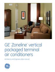
2008 contract sales architects and engineers data manual
Quick Reference<br />
Full Specs on pages 54 and 55<br />
ALL UNITS REQUIRE POWER CONNECTION KIT<br />
Power Connection Kit determines resistance heat output<br />
7000 Btuh units do not activate 5 KW resistance heater<br />
2900 Series Cooling with Electric Heat<br />
MODEL<br />
NUMBER<br />
COOLING<br />
(Btuh)<br />
EER<br />
AZ29E07DA* 7100/6900 12.7/12.7<br />
AZ29E09DA* 9300/8900 12.0/12.0<br />
AZ29E12DA* 11700/11500 11.5/11.5<br />
AZ29E15DA* 14600/14300 10.2/10.2<br />
AZ29E07EA* 7100 12.7<br />
AZ29E09EA* 9000 12.0<br />
AZ29E12EA* 11700 11.5<br />
AZ29E15EA* 14600 10.2<br />
3900 Series Heat Pump with Backup Electric Heat<br />
MODEL<br />
NUMBER<br />
COOLING<br />
(Btuh)<br />
EER<br />
REvERSE CyCLE<br />
BTUH<br />
COP<br />
AZ39H07DA* 7100/6900 12.7/12.7 6400/6200 3.6/3.6<br />
AZ39H09DA* 9400/9150 12.0/12.0 8550/8300 3.6/3.6<br />
AZ39H12DA* 11850/11500 11.5/11.5 11000/10700 3.4/3.4<br />
AZ39H15DA* 14800/14400 10.0/10.0 13900/13600 3.2/3.2<br />
AZ39H07EA* 7100 12.7 6400 3.6<br />
AZ39H09EA* 9000 12.0 8550 3.6<br />
AZ39H12EA* 11700 11.5 10900 3.4<br />
AZ39H15EA* 14750 10.0 13900 3.2<br />
5800 Series Heat Pump with Backup Electric Heat<br />
MODEL<br />
NUMBER<br />
COOLING<br />
(Btuh)<br />
EER<br />
REvERSE CyCLE<br />
BTUH<br />
COP<br />
AZ58H07DA* 7300/7000 13.0/13.0 6400/6200 3.7/3.7<br />
AZ58H09DA* 9300/9050 12.0/12.0 8400/8200 3.6/3.6<br />
AZ58H12DA* 11800/11600 11.7/11.7 10900/10700 3.4/3.4<br />
AZ58H15DA* 14700/14400 10.3/10.3 13800/13800 3.2/3.2<br />
AZ58H07EA* 7300 13.0 6400 3.7<br />
AZ58H09EA* 9300 12.0 8400 3.6<br />
AZ58H12EA* 11800 11.7 10900 3.4<br />
AZ58H15EA* 14700 10.3 13800 3.2<br />
2900, 3900 and 5800 Series<br />
Control Panel<br />
*Dual rated 230/208-volt units are shown with ratings separated by “/”.<br />
Units with single rating are 265-volt units.<br />
2<br />
Dry Air 25<br />
2900 Series Cooling with Electric Heat<br />
MODEL<br />
NUMBER<br />
COOLING<br />
(Btuh)<br />
EER<br />
AZ29E07DAP 6800/6600 12.1/12.1<br />
AZ29E09DAP 8800/8500 11.5/11.5<br />
AZ29E12DAP 11200/11000 11.0/11.0<br />
AZ29E07EAP 6800 12.1<br />
AZ29E09EAP 8900 11.5<br />
AZ29E12EAP 11200 11.0
Power Connection Kits<br />
230/208-Volt Line Cord Connection Units<br />
Line Cord<br />
Kit<br />
Electric<br />
Heat<br />
BTUH<br />
Electric<br />
Heater<br />
Watts<br />
Electric<br />
Heat<br />
Amps<br />
Electric Heat Amps include electric heater and fan motor current draw.<br />
265-volt units are to be permanently connected in compliance with National Electrical Code and local codes and have a factory-installed junction box on the chassis.<br />
Each 265-volt sub-base kit consists of sub-base with appropriate receptacle for minimum circuit amperage, chaseway to route power connector from sub-base to chassis<br />
and wiring to connect sub-base to building wiring.<br />
265-Volt Power Connection Kit must be ordered separately.<br />
Zoneline ® Chassis Nomenclature<br />
Min. Circuit<br />
Protection<br />
(Amps)<br />
RAK 15 8600/7100 2550/2090 11.6/10.6 15<br />
RAK 20 11700/9600 450/2820 15.5/14.1 20<br />
RAK 0 17100/1 900 5000/4090 22. /20. 0<br />
Electric Heat Amps include electric heater and fan motor current draw.<br />
Each Line Cord Kit has an integral Leakage Current Detection and Interruption (LCDI) or Arc Fault<br />
Current Interrupter (AFCI) device as required by National Electrical Code (NEC) and Underwriters<br />
Laboratories (UL) for units manufactured after August 1, 2004.<br />
265-Volt Sub-Base and Direct Connected Units<br />
The Zoneline chassis is identified by a model number defining the type of unit, cooling capacity, electrical information and<br />
optional features included on the unit. When specifying or ordering the Zoneline chassis, the use of this nomenclature will<br />
assure receiving the correct unit.<br />
ge.com<br />
230/208-Volt Sub-Base and Direct Connected Units<br />
Sub-Base<br />
Direct<br />
Connection<br />
Kit<br />
Electric<br />
Heat<br />
BTUH<br />
Electric<br />
Heater<br />
Watts<br />
Electric<br />
Heat<br />
Amps<br />
Min. Circuit<br />
Protection<br />
(Amps)<br />
RAK204D15P RAK4157 8600/7100 2550/2090 11.6/10.6 15<br />
RAK204D20P RAK4207 11700/9600 450/2820 15.5/14.1 20<br />
RAK204D 0P RAK4 07 170100/1 900 5000/4090 22. /20. 0<br />
Electric Heat Amps include electric heater and fan motor current draw.<br />
Units connected through sub-base do not require a LCDI or AFCI device since they are not<br />
considered to be line-cord connected. Each 2 0/208-volt sub-base kit consists of sub-base with<br />
appropriate receptacle for minimum circuit amperage, chaseway to route power connector from<br />
sub-base to chassis, wiring to connect sub-base to building wiring and a short line cord with 9-pin<br />
connector to connect to chassis and plug into receptacle in sub-base.<br />
Short sub-base line cord may not be used without sub-base.<br />
Junction box for 2 0/208-volt chassis must be purchased separately.<br />
RAK4002A for 2900 and 900 series units RAK4002B for 5800 series units.<br />
Sub-Base<br />
Power<br />
Connection Kit<br />
Direct<br />
Connection Kit<br />
Electric Heat<br />
BTUH<br />
Electric Heater<br />
Watts<br />
Electric Heat<br />
Amps<br />
Min. Circuit Protection<br />
(Amps)<br />
RAK204E15 RAK5172 RAK5157 8600 2550 9.6 15<br />
RAK204E20 RAK5202 RAK5207 11700 450 1 .0 20<br />
RAK204E 0 RAK5 02 RAK5 07 17000 5000 18.9 0<br />
Important<br />
Essential Elements Ordering Overview<br />
2 0/208-volt line cord connected units — order line cord kit<br />
2 0/208-volt sub-base connected units — order sub-base and junction box<br />
265-volt units — order sub-base and power connection kit<br />
EXAMPLE<br />
A Z 5 8 H 1 2 D A D<br />
Zoneline<br />
<strong>packaged</strong><br />
<strong>terminal</strong><br />
chassis<br />
Chassis series<br />
29= deluxe line cool/<br />
electric heat<br />
9=deluxe line heat pump<br />
58= premium line<br />
heat pump<br />
Unit type<br />
E= cooling with electric<br />
resistance heat<br />
H= heat pump with electric<br />
resistance heat<br />
Nominal cooling capacity<br />
07=7,000 BTUH cooling<br />
09=9,000 BTUH cooling<br />
12=12,000 BTUH cooling<br />
15=15,000 BTUH cooling<br />
Voltage/Phase/<br />
Frequency<br />
D= 2 0/208-Volt,<br />
single-phase, 60 Hz<br />
E= 265-Volt, single-phase,<br />
60 Hz<br />
Universal<br />
power connection<br />
Special Features<br />
B=base unit<br />
C=corrosion treated<br />
D= internal<br />
condensate<br />
removal (ICR)<br />
system (heat<br />
pump models<br />
only) (not for<br />
coastal areas)<br />
P= Dry Air 25 (2800<br />
Series only)
The Zoneline ® 2900, 900 and 5800 Series have incorporated changes suggested by customers, along with<br />
enhancements by <strong>GE</strong>’s Technology Team and changes necessary to meet new UL and NEC requirements.<br />
“L” shaped condenser coil.<br />
The “Partial Open Vent Air” feature was a specific request by a customer.<br />
“Heat Sentinel” is an enhancement developed by <strong>GE</strong>’s Technology Team to help lodging professionals welcome their guests<br />
with a moderate-temperature room and to help lower cooling costs.<br />
Devices have been added on cord-connected units to protect against injury from unsafe power cords.<br />
See the “Features and Benefits” section for in-depth explanation of these changes and the industry-leading features of<br />
<strong>GE</strong> Zoneline retained from the previous series.<br />
The Deluxe 2900 Series Zoneline Models Includes The “Dry Air 25” Models<br />
Which Remove 25% More Moisture Than Other Zoneline Models.<br />
Deluxe Dry Air 25 Models<br />
Cooling With Resistance Heat<br />
• Remove 25% More Moisture than other Zoneline Models,<br />
up to 2.7 Additional Gallons Per Day<br />
• Cool and Dry Air in Less Time than Standard Zoneline Models<br />
• Heat Pipe is a Separate Sealed Refrigerant System<br />
— No Mechanical Parts — No Special Maintenance Required<br />
• Helps Maintain Lower Relative Humidity In Rooms<br />
• Maintains Comfort at Slightly Higher Room Temperatures<br />
— Reduces Operating Costs — Provides Comfort Without<br />
Overcooling<br />
• Corrosion Treatment is Standard<br />
• Excellent Choice for Humid Climates<br />
• Available in 7000, 9000 and 12000 BTU Sizes<br />
The Dry Air 25 system, a heat pipe, is a hermetically sealed<br />
heat transfer surface installed in a “saddlebag” configuration<br />
around the indoor (evaporator) coil of the Zoneline. This coil<br />
arrangement will transfer heat from the front coil of the<br />
saddlebag to the rear coil without power consumption.<br />
This assembly uses R-22 as the refrigerant and is not<br />
connected to the regular Zoneline refrigerant circuit.<br />
4<br />
As warm, humid <strong>air</strong> is pulled through the pre-cool (front)<br />
section of the heat pipe, the heat removed from the <strong>air</strong> is<br />
absorbed by the refrigerant, causing the refrigerant to change<br />
to a gas and flow to the re-heat (rear) section of the heat<br />
pipe. The <strong>air</strong> leaving the pre-cool section of the heat pipe is<br />
cooler and at a higher relative humidity level than the room<br />
<strong>air</strong>. The pre-cooled <strong>air</strong> is further cooled as it passes through<br />
the evaporator; consequently, the relative humidity increases<br />
allowing the evaporator coil to remove more moisture.<br />
When the cold <strong>air</strong> from the evaporator comes in contact<br />
with the re-heat section of the heat pipe, the heat that was<br />
removed by the pre-cool section is added back to the <strong>air</strong> and<br />
the refrigerant in the heat pipe condenses and flows back<br />
to the indoor coil. The <strong>air</strong> discharged into the room by this<br />
process is much drier, creating a more comfortable room<br />
condition.<br />
The Newest Innovation from <strong>GE</strong><br />
The Dry Air 25 Models center around <strong>GE</strong>’s exclusive use of<br />
the patented Dinh ® Dehumidifier Heat Pipe from Heat Pipe<br />
Technology, Inc. This innovative NASA spin-off technology<br />
enables Dry Air 25 to remove 25% more moisture from the<br />
<strong>air</strong> than other leading manufacturers’ <strong>packaged</strong> <strong>terminal</strong> <strong>air</strong><br />
<strong>conditioners</strong>. This helps maintain room comfort at a higher<br />
room temperature, reducing operating costs.<br />
The Dry Air 25 keeps a room cool and dry, and this is the<br />
most important benefit when it comes to the occupant of<br />
the room — hotel guests, apartment residents, students.<br />
In a hot, humid climate, getting away from the humidity<br />
is just as important as the heat, and the Dry Air 25 is the<br />
perfect solution. The dehumidification of the Dry Air 25 has<br />
been verified by the same ARI test conditions that standard<br />
units are rated under. A list of customers using Dry Air 25 is<br />
available from <strong>GE</strong>.
Table of Contents<br />
Front Cover 1<br />
Mini Specs 2900, 900 and 5800 Series 2<br />
Mini Specs Power Connection Kits and Nomenclature<br />
The 2900/ 900/5800 and Dry 25 4<br />
Table of Contents 5<br />
Introduction 6<br />
The Zoneline System 7<br />
Features and Benefits<br />
Features Table 8<br />
Features and Benefits 9-11<br />
Auxiliary Control Switches 12-1<br />
Central Desk Control 14<br />
Remote Thermostat Control 15-17<br />
Heat Pumps and Energy Savings 18-19<br />
Installation and Dimensions<br />
Application Comments 20<br />
Case Dimensions 21<br />
Wall Case/Sub-Base Installation 22-<br />
Condensate Disposal Systems 4- 6<br />
Ducted Installations 7- 9<br />
Exterior Grilles 40-41<br />
Product Data<br />
Electrical Connection 42<br />
Essential Elements Ordering Overview 4<br />
Maximum Connected Load 44<br />
Cooling/Heat Pump Performance Data 45<br />
Latent System Capacity 46<br />
Normal Yearly Operating Data 47<br />
Schematics 48-51<br />
Product Specifications<br />
Suggested Bid Form Specifications 52-5<br />
Zoneline Chassis Nomenclature/Receptacles/Sub-bases 54<br />
Specifications 55<br />
Complete Accessory List 56<br />
General Installation Suggestions 57-58<br />
Warranty 58<br />
Alphabetical Index 59<br />
Back Cover 60<br />
Important Notice<br />
ge.com<br />
Equipment used as a primary source for<br />
heating or cooling is an integral part of<br />
the building in which it is installed. Proper<br />
application is essential for satisfactory<br />
performance over a wide range of<br />
operating conditions. It is strongly<br />
recommended that a professional<br />
engineer determine proper application.<br />
If this unit is a replacement unit, its<br />
specifications and performance<br />
may differ from those of the unit it is<br />
replacing. For that reason, we again<br />
strongly recommend that a professional<br />
engineer determine proper application.<br />
5
Introduction<br />
This manual is designed to provide product, performance<br />
and application information to our customers and their<br />
architects and engineers for use in selection and design<br />
of a zonal comfort control system utilizing <strong>GE</strong> Zoneline ®<br />
Packaged Terminal Air Conditioners (PTAC) and Packaged<br />
Terminal Heat Pumps (PTHP). <strong>GE</strong> Zoneline PTACs and PTHPs<br />
are self-contained units designed for through-the-wall<br />
installations in hotels, motels, apartments, hospitals,<br />
nursing homes, add-on rooms and many other installations.<br />
Zonelines provide individual room or zone control in both<br />
cooling and heating operation. There is a model for practically<br />
every application, ranging in cooling capacity from 7,100 to<br />
14,700 BTUH and heating capacity from 6,400 to 1 ,400 BTUH<br />
in heat pump operation. See pages 42 and 54 for resistance<br />
heaters available.<br />
Zoneline offers a two-tier lineup: the Deluxe Line and the<br />
Premium Line. The Deluxe Line consists of the 2900 Series<br />
with electric resistance heat, the 2900 Series Dry Air 25 Models<br />
with enhanced dehumidification for hot and humid climates<br />
and the 900 Series heat pump. The 900 Series heat pump<br />
features reverse cycle defrost and simultaneous supplemental<br />
resistance heat, when needed, to maintain room comfort.<br />
The Premium Line features the 5800 Series heat pump with<br />
reverse cycle defrost and supplemental resistance heat, when<br />
needed, to maintain room comfort, plus tactile touch controls<br />
with digital display and standard corrosion protection.<br />
Deluxe Line Standard Features:<br />
• Digital Controls<br />
—LED Temperature Display<br />
—Easy Temperature Selection<br />
—Tactile Touch Pad<br />
• Universal Heaters<br />
• 2 Fan Motors<br />
• Heat Sentinel<br />
• “L” Coil Design Condenser<br />
• -Position Vent Door<br />
• Freeze Sentinel<br />
• Indoor Coil Frost Control<br />
• Central Desk Control Interface<br />
• Remote Thermostat Control Interface<br />
• Random Restart<br />
• Electronic Temperature Limiting<br />
• “Smart Fan” Fan Cycle/Continuous Control<br />
• Transfer Fan Interface<br />
• Reverse Cycle Defrost and Simultaneous Supplemental<br />
Resistance Heat on Heat Pumps<br />
• Quick Heat Recovery<br />
Deluxe Line Optional Features:<br />
• Corrosion Protection<br />
• Internal Condensate Removal (on 900 Series Heat Pump<br />
without Corrosion Protection)<br />
NOTE: Dry Air 25 models include all the standard features of the 2900 Series plus<br />
standard corrosion protection.<br />
6<br />
Premium Line Standard Features:<br />
All the Standard Features of the Deluxe Line Plus:<br />
• Two fan motor system with Indoor Cross Flow Blower<br />
for quieter operation<br />
• Unit Diagnostics<br />
• Standard Corrosion Protection Treatment<br />
Premium Line Optional Features:<br />
• Internal Condensate Removal (Not for use in seacoast<br />
or corrosive areas)<br />
Advantages of the <strong>GE</strong> Zoneline System:<br />
• Flexible Application<br />
— May be installed from flush to finished floor to " from<br />
the ceiling<br />
— 7,100 to 14,700 BTUH units in same physical size<br />
— Deluxe 2900 and 900 Series may be ducted to condition<br />
more than one room<br />
— Compatible with Class 2 remote thermostat control<br />
— Compatible with 2 wire CDC or many Energy<br />
Management systems<br />
• Economical Installation<br />
— No ductwork necessary<br />
— No mechanical equipment rooms or pipes required for<br />
heating/cooling units<br />
— Replacement units fit existing 42"-wide by 16"-high<br />
wall cases<br />
• Quiet Operation<br />
— Indoor double cut-off scroll: two fan motor 2900 and 900<br />
Series units<br />
— Indoor cross-flow blower: 2 fan motor 5800 Series units<br />
• Energy-Saving Operation<br />
— Units in unoccupied areas may be turned off<br />
— Designed for efficient cooling operation — EERs from 10.0<br />
to 1 .0<br />
— Efficient heat pump units — COPs from .2 to .6<br />
— Extended heat pump operation without sacrificing<br />
room comfort<br />
• Ease of Maintenance<br />
— Permanently lubricated fan motors<br />
— Upfront lift-out interchangeable filters<br />
— Air Discharge area is easily accessed for cleaning<br />
— Slide-out chassis for easy access for cleaning or if<br />
service is required<br />
• Reverse Cycle Heat Pump Operation<br />
Both the 900 and the 5800 Series heat pumps utilize<br />
the unique <strong>GE</strong> PTAC heat pump operation to ensure a<br />
comfortable room. The logic used by the units is the<br />
same logic used by central system heat pumps to<br />
provide greater savings.
The Zoneline ® System<br />
ge.com<br />
The typical Zoneline installation consists of the wall case (or sleeve), chassis, and exterior grille. Some installations may<br />
use a sub-base for support of the unit or for ease of electrical connections. Each of the components should be the standard<br />
products offered by <strong>GE</strong> or, in the case of the exterior grille, approved by <strong>GE</strong> Applications Engineering. Use of components not<br />
specifically designed or approved for use with the Zoneline can result in unsatisfactory operation and can be the cause of<br />
failure not covered by the warranty.<br />
Components of the Zoneline System<br />
Typical Installation (Deluxe Series shown)<br />
Room Cabinet<br />
Chassis<br />
Optional Accessories of the Zoneline System<br />
RAK204D20P Sub-Base (shown)<br />
Power Supply Cord (included with 208v/2 0v<br />
sub-bases)<br />
Chaseway<br />
See pages 22 and 2 for information on electrical sub-bases and chaseway.<br />
See pages 7- 9 for information on ducted installations.<br />
Power Connection Kit (required on all units)<br />
Line Cord Kit shown<br />
See pages 42-4<br />
RAK6052 Duct Adapter<br />
(For Deluxe Series)<br />
RAK601/602 (For Deluxe Series)<br />
Duct Extension, Register and Trim Flange<br />
Wall Case<br />
RAB71A (Steel-Insulated)<br />
RAB77A4 (SMC — Molded)<br />
Wall Case Options<br />
(See page 22)<br />
RAG67 (shown)<br />
Grill Options<br />
(See page 40)<br />
Power Supply Cord<br />
7
Zoneline ® Features<br />
AZ AZ AZ<br />
2900 3900 5800<br />
Enhanced Dehumidification — Dry Air 25 Optional N/A N/A<br />
Cooling EER Range (2 0 Volts/265 Volts) 10.2 - 12.7 10.0 - 12.7 10.2 - 1 .0<br />
Heating COP Range (2 0 Volts/265 Volts) N/A .2 - .6 .2 - .6<br />
Heat Source — Electric Resistance Heat Standard — —<br />
Heat Source — Heat Pump With Selectable<br />
Full Time or On Demand Simultaneous/<br />
Supplemental Resistance Heat — Standard Standard<br />
Staged Heating — Stage Stage<br />
Universal Heater — UPC* Standard Standard Standard<br />
Unit Controls<br />
Electronic Temperature Selection<br />
Touch Pad Touch Pad Touch Pad<br />
(Slews Up & Down) with Digital Display Standard Standard Standard<br />
Unit Diagnostics — — Standard<br />
Highly Featured Microprocessor Controls Standard Standard Standard-Plus<br />
Electric Resistance Heat Lock-Out (above 46°F) — Standard Standard<br />
Automatic Emergency Heat — Standard Standard<br />
Heat Pump Defrost System — Reverse Cycle Reverse Cycle<br />
High Temperature Operation Protection — Standard Standard<br />
Quick Heat Recovery — Standard Standard<br />
Temperature Boost Selectable Selectable<br />
Service Indicator — — Temp Display Blinks<br />
Fan Motors — Permanently Lubricated 2 2 2<br />
2-Speed Outdoor Fan Standard Standard Standard<br />
Indoor Fan Speed Selections — HIGH/LOW HIGH/LOW/AUTO HIGH/LOW/AUTO HIGH/LOW/AUTO<br />
Fan Only Setting — HIGH/LOW Standard Standard Standard<br />
Fan Cycle Switch “Smart Fan” “Smart Fan” “Smart Fan”<br />
Constant-Run Fan Selectable Selectable Selectable<br />
Rotary Compressor Standard Standard Standard<br />
Automatic Compressor Restart Delay Standard Standard Standard<br />
Freeze Sentinel Standard Standard Standard<br />
Heat Sentinel Standard Standard Standard<br />
Indoor Coil Frost Control Standard Standard Standard<br />
Transfer Fan Connections Standard Standard Standard<br />
7-Step Electronic Temperature Limiting Standard Standard Standard<br />
Remote Control Capability with Wall Mounted Thermostat Standard Standard Standard<br />
Central Desk Control Capability Standard Standard Standard<br />
Energy Management System Interface with Load Shedding Option Standard Standard Standard<br />
Reversible Indoor Air Louvers 40º/50º Standard Standard Standard<br />
Up-Front Filters Standard Standard Standard<br />
Easy-Clean Air Discharge Area Standard Standard —<br />
Concealed Manual Vent Control Standard Standard Standard<br />
Ducted Installation Capability RAK6052 RAK6052 —<br />
Corrosion Protection (Standard on Dry Air 25)<br />
Internal Condensate Removal (ICR) (Factory Installed Option.<br />
Optional Optional Standard<br />
Cannot be used in Corrosion Areas.)<br />
*UPC — Universal Power Cord Connection (See pages 42 and 54).<br />
265-volt units must be connected in a manner to meet National Electrical Code and all local codes.<br />
N/A Optional Optional<br />
8
Features and Benefits<br />
Standard Physical Dimensions<br />
<strong>GE</strong> has maintained the same dimensions since 1961 —<br />
42" wide x 16" high x 1 - /4" deep<br />
Replacement of older units is made easy.<br />
Weather-Protected Electrical Components<br />
Vital electrical components are protected from the weather<br />
by locating them on the indoor side of the weather barrier.<br />
Weather-Resistant “Superseal”<br />
Properly installed unit in undistorted case keeps <strong>air</strong> leakage<br />
to a minimum.<br />
7 CFM <strong>air</strong> infiltration with 25 MPH wind on non-ICR units —<br />
10 CFM on units with ICR.<br />
Industry specification is 19 CFM of <strong>air</strong> infiltration.<br />
Heater Sizes to Meet Room Requirements<br />
All units are equipped with a universal heater —<br />
the resistance heat output is determined by power<br />
connection kit.<br />
230/208-volt — Line Cord Connected Units — 2.55/2.09 KW<br />
with RAK 15 — 15-amp circuit; .45/2.82 KW with<br />
RAK 20 — 20-amp circuit; 5.0/4.09 KW with RAK 0 —<br />
0-amp circuit.<br />
230/208-volt - Sub-Base Connected Units — 2.55/2.09<br />
KW with RAK204D15P — 15-amp circuit; .45/2.82 KW<br />
with RAK204D20P — 20-amp circuit; 5.0/4.09 KW with<br />
RAK204D 0P — 0-amp circuit.<br />
265-volt — 2.55 KW with RAK5172 — 15-amp circuit; .45 KW<br />
with RAK5202 — 20-amp circuit; 5.0 KW with RAK5 02 —<br />
0-amp circuit.<br />
Unit Controls<br />
2900 and 3900 Series — touch pad controls for temperature<br />
and operation selection.<br />
5800 Series — touch pad controls with digital readout of<br />
temperature set point.<br />
Highly Featured Microprocessor Controls<br />
Microprocessor controls are programmed to interface with<br />
the temperature sensors to maximize comfort conditions for<br />
the room occupant and provide outstanding features.<br />
Thermistors are used to sense small changes in temperature<br />
to give excellent room control and allow the microprocessor<br />
to monitor and react to changing conditions.<br />
Electric Resistance Heat Lock-Out<br />
To maximize the savings of the heat pump operation, the<br />
Zoneline heat pumps do not utilize the resistance heater<br />
when the outdoor temperature is above 46°F during normal<br />
operation. The resistance heat is used in the Quick Heat<br />
Recovery feature.<br />
Automatic Emergency Heat<br />
Automatically uses electric resistance heat if the heat<br />
pump output is not sufficient to maintain selected<br />
room temperature.<br />
ge.com<br />
Reverse Cycle Heat Pump Defrost System<br />
Standard on all Zoneline 900 and 5800 Series heat pumps.<br />
Enables heat pump to operate at lower temperatures<br />
when other systems switch to more expensive electric<br />
resistance heat.<br />
See pages 18 and 19 for discussion of heat pump operation<br />
and defrost systems.<br />
High Temperature Heat Pump Operation Protection<br />
Automatically protects the compressor if heat pump is<br />
operated with high outdoor temperatures.<br />
Power to the outdoor fan is turned off if the indoor coil gets<br />
too hot during heat pump operation to prevent damage to<br />
the compressor.<br />
Quick Heat Recovery – Heat Pump Units<br />
When the unit operation is changed from STOP or COOL to<br />
HEAT, the electric resistance heaters are used to warm the<br />
room to the thermostat set point. This provides faster room<br />
temperature increase for greater guest comfort.<br />
Unit Diagnostics<br />
The 5800 Series has a dip switch that activates each of<br />
the various components of the unit to operate briefly. This<br />
enables the technician to determine if individual components<br />
are functioning properly.<br />
Service Indicator<br />
On the 5800 Series, if the microprocessor detects a<br />
compressor malfunction, the digital temperature display<br />
will blink. If the malfunction occurs during cooling operation,<br />
the indoor fan will continue to operate. If the compressor<br />
malfunctions in heating mode, the unit will automatically<br />
switch to resistance heat to maintain room temperature set<br />
point. <strong>GE</strong> Service should be called to check the Zoneline.<br />
Fan Motors – Permanently Lubricated<br />
All units have two fan motors for quiet operation and<br />
maximum operating efficiency.<br />
Motors are permanently lubricated to reduce maintenance<br />
and totally enclosed to keep dirt and water out of the motor<br />
windings.<br />
2-Speed Outdoor Fan<br />
The unit automatically selects the most efficient speed for<br />
the outdoor fan. The operating sound level is lower when the<br />
outdoor fan can operate in low speed yet there are situations<br />
where it must operate in high speed. The unit changes the<br />
fan speed automatically.<br />
Indoor Fan Speed Selections – HIGH/LOW<br />
Unit may be operated in HIGH HEAT or LOW HEAT or HIGH<br />
COOL or LOW COOL.<br />
9
Features and Benefits<br />
Fan-Only Setting – HIGH/LOW<br />
The unit provides the option of selecting either HIGH or LOW<br />
speed for Fan-Only operation.<br />
Fan-Cycle Switch – “SmartFan”<br />
Unique “SmartFan” allows unit to operate fan continuous in<br />
cooling operation and fan cycle in heating to provide better<br />
guest comfort. Eliminates complaint of cold <strong>air</strong> draft during<br />
heating operation.<br />
Eliminates need of changing fan-cycle switch seasonally.<br />
“SmartFan” settings are controlled by two dip switches on<br />
auxiliary control panel.<br />
Compressor Random Restart<br />
In the event of a power failure, all compressors attempting<br />
to restart immediately when power is restored can result<br />
in a power surge that can cause another power interruption.<br />
The microprocessors in the Zonelines have a random restart<br />
logic system that prevents all units from starting at the<br />
same time.<br />
Rotary Compressor<br />
Smoother operation for quiet, dependable service. <strong>GE</strong> has<br />
used rotary compressors since 1961.<br />
Compressor Restart Delay<br />
Zonelines are designed to provide a minimum of three<br />
minutes of compressor off time to allow refrigerant pressures<br />
to equalize before restarting to prevent compressor damage.<br />
Zonelines are also designed to provide a minimum of three<br />
minutes of compressor run time to prevent room occupant<br />
disturbance due to short-cycling of the <strong>air</strong> conditioner.<br />
Freeze Sentinel <br />
Detects low room temperature and turns on heater to<br />
help protect against damage caused by freezing room<br />
temperature.<br />
Heater turns on at 41°F and warms indoor thermistor<br />
temperature to 46°F and shuts off.<br />
Freeze Sentinel may be turned off by dip switch on<br />
auxiliary control.<br />
Heat Sentinel<br />
The property owner may choose to activate the Heat<br />
Sentinel feature on the Zoneline. If the Heat Sentinel is<br />
activated and room temperature reaches 85°F while the<br />
unit is in the “STOP” setting, the unit will automatically start<br />
in <strong>air</strong> conditioning operation and will shut off when the room<br />
temperature reaches 80°F. This will help dehumidify the <strong>air</strong><br />
and lower high temperatures so the guest will not be entering<br />
an extremely hot room.<br />
10<br />
Indoor Coil Frost Control<br />
Transfer Fan Interface<br />
Prevents indoor coil from freezing<br />
and causing complaints due to lack<br />
of cooling. Frost can form on the<br />
indoor coil when the unit is operated<br />
in cooling when outdoor temperatures<br />
are low. The unit automatically shuts<br />
the compressor off until the indoor coil<br />
temperature warms to the point where<br />
frosting will no longer occur.<br />
24 VAC <strong>terminal</strong>s are provided to operate a relay to control<br />
a fan mounted in a wall to move conditioned <strong>air</strong> into another<br />
space. The electrical power for the operation of the transfer<br />
fan itself is not provided by the Zoneline. Transfer fans and<br />
their controlling relays are field supplied.<br />
Electronic Temperature Limiting<br />
Seven independent programmable heating temperature limits<br />
and seven independent programmable cooling temperature<br />
limits. Eliminates need to reset the limits seasonally.<br />
Remote Control Capability with Wall-Mounted<br />
Thermostat<br />
See pages 15-17.<br />
Central Desk Control Capability<br />
See page 14.<br />
Heating Temperature Limits<br />
Energy Management System Interface with<br />
Load Shedding Option<br />
All units have a switch on the auxiliary control panel to<br />
allow the indoor fan to continue operating if the unit is<br />
connected to an Energy Management System that shuts<br />
off compressor or heater operation. By allowing the indoor<br />
fan to run when the heater or compressor is shut off by the<br />
Energy Management System, the guest is less likely to realize<br />
the operation of the unit has been altered. This helps reduce<br />
peak energy demand loads without disturbing the room<br />
occupant.<br />
Reversible Indoor Air Louvers<br />
Allows <strong>air</strong> to be directed into room at 40º or 50º angle to<br />
provide better <strong>air</strong> distribution.<br />
Angle is changed by removing room front and screws<br />
holding louver in place, and rotating louver section.<br />
Highest<br />
Heat<br />
65 70 72 74 76 78 80 85<br />
Lowest<br />
Cool<br />
Cooling Temperature Limits<br />
60 64 66 68 70 72 74 76<br />
Limits are set by dip switches on auxiliary control panel.
Features and Benefits<br />
Easy Clean Air Discharge Area<br />
Up-Front Air Filters<br />
Two interchangeable<br />
up-front filters, easy<br />
to remove and reinstall,<br />
may be cleaned without<br />
opening or removing<br />
the room front.<br />
Clean filters by brushing,<br />
vacuuming or backflushing<br />
under faucet<br />
or shower head.<br />
2900 and 3900 Series units have an out-of-sight vertical<br />
protective screen over the indoor fan. This allows easy<br />
cleaning of <strong>air</strong> discharge area by simply removing room<br />
front and wiping clean.<br />
There is no screen directly below discharge louver to trap<br />
unsightly dirt and debris where it may be seen by room<br />
occupant.<br />
Concealed Manual<br />
Vent Control<br />
The -position manual vent<br />
door control may be closed,<br />
partially open or fully open.<br />
Vent CFM High Speed<br />
Unit Full Open Partial Open<br />
7000 50 40<br />
9000 70 45<br />
12000 75 45<br />
15000 75 45<br />
CFM ratings at 2 0 volts and 265 volts.<br />
Greater amounts of <strong>air</strong> will be introduced if the room has an<br />
exhaust fan.<br />
An open vent door brings unconditioned outdoor <strong>air</strong> into the<br />
room, increasing heating and cooling costs.<br />
Positive vent door closure prevents accidental opening and<br />
unwanted <strong>air</strong> infiltration.<br />
Corrosion Protection (Optional)<br />
2900 and 900 Series units may be ordered with special<br />
protection to better withstand damage from salt <strong>air</strong> and<br />
salt water in seacoast areas.<br />
ge.com<br />
Corrosion protection is standard on the 5800 Series and<br />
on Dry Air 25 models.<br />
Heat Pump units with ICR are not available with corrosion<br />
protection and should not be installed in seacoast or<br />
corrosive environments.<br />
Units installed in corrosive areas should be examined and<br />
cleaned more frequently than normal installations.<br />
Internal Condensate Removal (ICR)<br />
See page 4 for a discussion of the Internal Condensate<br />
Removal system available on 900 and 5800 Series heat pumps.<br />
Enhanced Dehumidification<br />
Moisture removal is an important function of an <strong>air</strong><br />
conditioner. People are more comfortable at higher<br />
temperatures when the humidity level is relatively low.<br />
Air <strong>conditioners</strong> operate with less energy consumption<br />
when the room temperatures are set higher.<br />
The <strong>GE</strong> Zoneline ® 2900 Series with the Dry Air 25 heat pipe<br />
application removes 25% more moisture than the base<br />
2900 Series unit.<br />
The <strong>GE</strong> Zoneline Dry Air 25 chassis is the only PTAC available<br />
with the application of the patented Dinh ® Dehumidifier<br />
Heat Pipe under license from Heat Pipe Technology, Inc.<br />
Customers who are using the Dry Air 25 report a freshersmelling<br />
room as a result of the lower humidity levels, as<br />
well as lower operating costs.<br />
Locking Door Kit<br />
RAK8023 — A door with a lock that replaces the standard<br />
control cover door to prevent unauthorized changing of<br />
control setting is offered as an accessory.<br />
11
Auxiliary Control Switches<br />
These switches are located behind the room cabinet under the control panel.<br />
2900 and 3900 Series<br />
Switches Description<br />
Left Switches<br />
(1) ALL I2R Heat pump override —<br />
Down — Normal heat pump operation<br />
Up — resistance heat only ( 900 Series only)<br />
(2) C: FAN Fan control for cooling operation —<br />
Down — Fan Continuous<br />
Up — Fan Cycle<br />
( ) H: FAN Fan control for heating operation —<br />
Down — Fan Cycle<br />
Up — Fan Continuous<br />
(4) CLASS 2 Remote Thermostat Mode —<br />
Down — Unit Control<br />
Up — Remote Thermostat<br />
(5) LOAD SHED Load Shedding when connected to Central Desk Control System —<br />
Down — Fan shuts off with unit<br />
Up — Fan under “Smart Fan” settings<br />
(6) FREEZ S Freeze Sentinel Override —<br />
Down — Freeze Sentinel ON<br />
Up — Freeze Sentinel OFF<br />
(7) CONST FAN Constant Fan —<br />
Down — Fan runs normally<br />
Up — Fan runs when unit is in STOP position<br />
Right Switches<br />
TL1 – TL Cooling temperature limiting (See table at bottom of page)<br />
TL4 – TL6 Heating temperature limiting (See table at bottom of page)<br />
(7) Heat Sentinel switch —<br />
Down — Heat Sentinel OFF<br />
Up — Heat Sentinel ON<br />
(8) Heat Boost ( 900 series only) —<br />
Down — Heat Boost OFF<br />
Up — Heat Boost ON<br />
Auxiliary (2900 and 900 series)<br />
900 Series shown<br />
12<br />
UP<br />
DOWN<br />
ALLI 2 R (All Electric Heat)<br />
(3900 Series models only)<br />
C: FAN CN (Cooling–Smart Fan)<br />
H: FAN CY (Heating–Smart Fan)<br />
CLASS 2 (Remote Thermostat)<br />
LOAD SHEDDING (CDC)<br />
FREEZ Sen (Freeze Sentinel)<br />
CONST FAN (Constant ON Fan)<br />
NO FUNCTION (Reserved for future use)<br />
1 2 3 4 5 6 7 8 1 2 3<br />
HIGH<br />
COOL 4 5 6<br />
7 8<br />
UP<br />
DOWN<br />
HEAT BOOST<br />
(3900 Series models only)<br />
Heat Sentinel<br />
TL1 (H) (Temp. Limit 1–Heat)<br />
TL2 (H) (Temp. Limit 2–Heat)<br />
TL3 (H) (Temp. Limit 3–Heat)<br />
TL1 (C) (Temp. Limit 1–Cool)<br />
TL2 (C) (Temp. Limit 2–Cool)<br />
TL3 (C) (Temp. Limit 3–Cool)<br />
Cooling and Heating temperature limits are set independently, temperature limiting<br />
switches are in factory-set down position, except as noted.<br />
Cooling Temperature Limits<br />
Switches Up NONE 1 1, 2 2 2, 1, 2, 1,<br />
60 64 66 68 70 72 74 76<br />
Heating Temperature Limits<br />
Switches Up 6 4, 6 4, 5, 6 5, 6 5 4, 5 4 NONE<br />
65 70 72 74 76 78 80 85
Auxiliary Control Switches<br />
These switches are located behind the room cabinet under the control panel.<br />
5800 Series<br />
Switches Description<br />
Left Switches<br />
(1) ALL I2R Heat pump override —<br />
Down — Normal heat pump operation<br />
Up — resistance heat only<br />
(2) C: FAN Fan control for cooling operation —<br />
Down — Fan Continuous<br />
Up — Fan Cycle<br />
( ) H: FAN Fan control for heating operation —<br />
Down — Fan Cycle<br />
Up — Fan Continuous<br />
(4) CLASS 2 Remote Thermostat Mode —<br />
Down — Unit Control<br />
Up — Remote Thermostat<br />
(5) LOAD SHED Load Shedding when connected to Central Desk Control System —<br />
Down — Fan shuts off with unit<br />
Up — fan under “Smart Fan” settings<br />
(6) FREEZ S Freeze Sentinel Override —<br />
Down — Freeze Sentinel ON<br />
Up — Freeze Sentinel OFF<br />
(7) CONST FAN Constant Fan —<br />
Down — Fan runs normally<br />
Up — fan runs when unit is in STOP position<br />
(8) OCCUPIED Occupancy Sensor Mode —<br />
Down — Unit Control<br />
Up — Occupancy Sensor Connected<br />
Right Switches<br />
TL1 – TL Cooling temperature limiting (See table at bottom of page)<br />
TL4 – TL6 Heating temperature limiting (See table at bottom of page)<br />
(7) Diagnostics Switch<br />
(8) Heat Sentinel switch —<br />
Down — Heat Sentinel OFF<br />
Up — Heat Sentinel ON<br />
(9) Heat Boost —<br />
Down — Heat Boost OFF<br />
Up — Heat Boost ON<br />
5800 Series shown<br />
UP<br />
DOWN<br />
ALLI 2 R (All Electric Heat)<br />
C: FAN CN (Cooling–Smart Fan)<br />
H: FAN CY (Heating–Smart Fan)<br />
CLASS 2 (Remote Thermostat)<br />
LOAD SHEDDING (CDC)<br />
FREEZ Sen (Freeze Sentinel)<br />
CONST FAN (Constant ON Fan)<br />
OCCUPIED (Occupancy Sensor)<br />
1 2 3 4 5 6 7 8 1 2 3<br />
HIGH<br />
COOL 4 5 6<br />
Cooling and Heating temperature limits are set independently, temperature limiting<br />
switches are in factory-set down position, except as noted.<br />
Cooling Temperature Limits<br />
Switches Up NONE 1 1, 2 2 2, 1, 2, 1,<br />
60 64 66 68 70 72 74 76<br />
Heating Temperature Limits<br />
7 8 9<br />
Switches Up 6 4, 6 4, 5, 6 5, 6 5 4, 5 4 NONE<br />
UP<br />
DOWN<br />
HEAT BOOST<br />
Heat Sentinel<br />
Diagnostics Switch<br />
TL1 (H) (Temp. Limit 1–Heat)<br />
TL2 (H) (Temp. Limit 2–Heat)<br />
TL3 (H) (Temp. Limit 3–Heat)<br />
TL1 (C) (Temp. Limit 1–Cool)<br />
TL2 (C) (Temp. Limit 2–Cool)<br />
TL3 (C) (Temp. Limit 3–Cool)<br />
65 70 72 74 76 78 80 85<br />
ge.com<br />
1
Central Desk Control<br />
Some installations may want to govern the ability of the unit<br />
to operate from a control device remote to the unit or even<br />
remote to the room in which the unit is located. The general<br />
term given to systems such as this is Central Desk Control.<br />
The most common installation of this type of system is a<br />
switch mounted at the registration desk and, upon guest<br />
check-in, a button is pushed or a switch is moved to allow<br />
the <strong>air</strong> conditioner to operate. Likewise, when the guest<br />
checks out the device is put into the “OFF” position so the<br />
unit will not operate while the room is vacant.<br />
It is not necessary that the controlling device be located<br />
at a central desk to employ a device that will control the<br />
unit operation. For instance, in some resort areas devices<br />
are connected to sliding glass doors and opening the door<br />
causes a contact to close, turning the <strong>air</strong> conditioner off.<br />
This prevents energy being wasted by operating the <strong>air</strong><br />
conditioner when warm, humid <strong>air</strong> is entering the room.<br />
Some systems operate by motion sensors or heat sensing<br />
detectors mounted in the room. These types of systems<br />
determine occupant presence in the room and allow the<br />
unit to operate; if no one is in the room the device signals<br />
the <strong>air</strong> conditioner to turn off.<br />
Zoneline ® models offer Load-Shedding capabilities on<br />
units connected to Central Desk Control Systems. For more<br />
information on the models’ Load-Shedding Feature, see<br />
page 10.<br />
There is a wide variety of devices available, each with<br />
its own benefits and constraints. While <strong>GE</strong> does not offer<br />
components that are external to the unit for a Central Desk<br />
Control (CDC) system, <strong>GE</strong> Zonelines are compatible with most<br />
CDC and Energy Management systems. Zonelines provide a<br />
24 VAC circuit that powers the Central Desk Control system<br />
and no external power is needed.<br />
All Zoneline 2900, 900, and 5800 Series units are compatible<br />
with simple on/off 2-wire Central Desk Control systems.<br />
Consult with the provider of other energy management<br />
systems to be sure they are compatible with the <strong>GE</strong> Zoneline.<br />
Zonelines have standard connectors factory-installed to<br />
provide a CDC interface that permits the unit to be connected<br />
to most of the energy management systems. The devices<br />
connected to the Zoneline units require no power supply or<br />
transformers external to the unit.<br />
Important CDC Comments (all series applicable)<br />
1. When the switching device closes the circuit of the CDC<br />
conductors, the unit operation stops.<br />
2. Do not use a common buss (at the unit or at the switch<br />
panel) in the wiring. Both wires comprising the circuit must<br />
connect to the unit connectors and to the controlling<br />
switch. Running one wire from one unit to another unit is<br />
common bussing and may damage internal components<br />
or cause erratic operation of the system.<br />
. A 24-volt transformer is contained within the Zoneline.<br />
No external voltage may be applied to the unit through<br />
the CDC <strong>terminal</strong>s. (Voltage on the CDC conductors is<br />
24 volts AC.)<br />
14<br />
4. Recommended wire size must be followed as a minimum<br />
requirement.<br />
Wire Size #AWG Maximum Allowable Length<br />
#22 600 Ft.<br />
#20 900 Ft.<br />
#18 1500 Ft.<br />
#16 2000 Ft.<br />
Freeze Sentinel remains operational when the unit is<br />
connected to a CDC system. Even if the unit is turned “OFF” at<br />
the central location, if the sensor at the unit detects the low<br />
temperature, the electric resistance heaters and the fan will<br />
automatically turn on.<br />
Connecting the Zoneline to a CDC system does not eliminate<br />
the ability to connect the unit to a remote thermostat.<br />
Once the circuit is “opened,” and control of the unit removed<br />
from the CDC system, the selected controls - either the unit<br />
mounted control or the remote thermostat - govern the<br />
operation of the unit.<br />
Please see page 57 for installation recommendations for<br />
the Central Desk Control wiring.<br />
CDC Terminal Location and Typical Wiring<br />
See page 15 for location of CDC <strong>terminal</strong>s on unit.<br />
Example of Common Bussing<br />
NOT PERMITTED<br />
Unit #1 Unit #2 Unit #3<br />
INCORRECT Common Bussing<br />
Normally Open<br />
Switch -<br />
Unit Operational<br />
CDC Terminals<br />
on Zoneline<br />
Typical Wiring<br />
(All Wiring Shown Is Field Supplied)
Remote Thermostat Control<br />
In some installations, control of the operation of the unit at<br />
a location remote from the unit itself may be desired. A unit<br />
mounted high in the wall or over a door, for instance, where<br />
the unit-mounted controls are inaccessible, can be connected<br />
to a wall-mounted thermostat. Other installations may use<br />
remote thermostat control for design or performance<br />
enhancement. The unit is connected to the thermostat by<br />
low-voltage wiring which permits the operation of the unit to<br />
be selected and the temperature sensed at the thermostat.<br />
Important Notes: Remote thermostat wiring should not be<br />
run through wall case. Thermostat wiring should exit the<br />
wall below the unit and enter the unit between room cabinet<br />
and chassis. Wire molding may be used to hide thermostat<br />
wiring. If a sub-base is used, the thermostat wiring may be<br />
concealed by the sub-base. Thermostat wiring should not be<br />
run parallel to line voltage wires since induced current may<br />
cause erratic operation.<br />
All Zoneline 2900, 900 and 5800 Series units are adaptable<br />
to Class 2 remote low-voltage thermostat. The only additional<br />
field-supplied components are the remote thermostat and<br />
wiring necessary to connect it.<br />
The controls on the unit are not functional when the remote<br />
control function is used.<br />
Resistance Heat Models<br />
The Zoneline 2900 resistance heat units may be connected to<br />
a single-stage thermostat designed for use with cooling with<br />
electric heat systems. <strong>GE</strong> offers three thermostats<br />
compatible with the 2900 Series unit.<br />
RAK163A1 —<br />
a mechanical<br />
manual<br />
changeover<br />
thermostat<br />
requiring four<br />
connection wires.<br />
RAK164D1 —<br />
a solid-state<br />
digital manual<br />
changeover<br />
thermostat<br />
requiring five<br />
connection wires.<br />
RAK164P1 —<br />
a solid-state digital<br />
programmable<br />
auto-changeover<br />
thermostat<br />
requiring five<br />
connection wires.<br />
The Class 2 Mode Switch (dip switch #4 on the auxiliary control<br />
board) must be set to the ON/UP mode to enable remote<br />
thermostat control. Refer to installation instructions <strong>packaged</strong><br />
with the chassis.<br />
Please see page 57 for installation recommendations for<br />
the remote thermostat wiring.<br />
Compatibility of other thermostats considered for use with the<br />
<strong>GE</strong> Zoneline is the responsibility of the customer. The control<br />
voltage on the remote control conductors is 24 volts AC.<br />
The AC voltage may not be compatible with some<br />
solid-state thermostats.<br />
ge.com<br />
The fan speed for the 2900 Series in remote thermostat<br />
operation is selected by the connection of the fan wire from<br />
the thermostat to either the HIGH or LOW <strong>terminal</strong> on the unit.<br />
See the sketch of the unit <strong>terminal</strong>s for the location of the HIGH<br />
and LOW fan-speed <strong>terminal</strong>s. Operating the unit in low fan<br />
speed reduces the operating sound level of the unit.<br />
Freeze Sentinel remains operational if the unit is connected to<br />
a remote thermostat. The unit may be connected to a Central<br />
Desk Control (CDC) system and controlled with a remote<br />
thermostat when the CDC system has the unit in operation.<br />
See page 14 for additional information on the CDC system.<br />
Unit temperature limiting switches are not functional when<br />
unit is connected to a remote thermostat.<br />
Field Wiring Terminal<br />
R — 24V AC<br />
GL — Low-Speed Fan<br />
GH — High-Speed Fan<br />
B — Not Used on 2900<br />
Y — Compressor<br />
W — Heater<br />
C — Common — Ground<br />
R<br />
CDC<br />
GL<br />
R<br />
GH<br />
GL<br />
B<br />
GH<br />
Resistance Heat Models<br />
Y<br />
B<br />
W<br />
Y<br />
C<br />
W<br />
C<br />
Common — Ground<br />
White — Heater<br />
Yellow — Compressor<br />
Black — Not Used On 2800<br />
Green — High-Speed Fan<br />
Green — Low-Speed Fan<br />
Red — 24V AC<br />
CDC Terminal<br />
RAK806 Universal Control Cover Label<br />
When a Zoneline unit<br />
is using a remote<br />
thermostat control,<br />
the RAK806 Universal<br />
Control Cover Label is<br />
recommended. The<br />
RAK806 is only<br />
available in a<br />
package of 10 labels.<br />
The label is placed<br />
over the control panel<br />
directing the user to<br />
Heat the Pump wall Models thermostat<br />
for operation of the<br />
Zoneline unit.<br />
Common — Ground<br />
White — Heater<br />
Yellow — Compressor<br />
Black — Reversing Valve<br />
Green — High-Speed Fan<br />
Green — Low-Speed Fan<br />
Red — 24V AC<br />
15
Remote Thermostat Control<br />
Heat Pump Models<br />
The Zoneline ® 900 and 5800 Series heat pump units may<br />
be connected to a single-stage cooling/two-stage heating<br />
thermostat designed for use with heat pump systems. <strong>GE</strong><br />
offers 2 thermostats compatible with the 900 and 5800<br />
series units:<br />
RAK148D1 —<br />
solid-state digital<br />
manual<br />
changeover<br />
thermostat<br />
requiring 6<br />
connection wires.<br />
16<br />
RAK148P1 —<br />
solid-state digital<br />
programmable<br />
auto-changeover<br />
thermostat<br />
requiring 6<br />
connection wires.<br />
Please see page 57 for installation recommendations for the<br />
remote thermostat wiring. Compatibility of other thermostats<br />
considered for use with the <strong>GE</strong> Zoneline ® is the responsibility<br />
of the customer.<br />
The control voltage on the remote control conductors is 24 VAC.<br />
The Class 2 Mode Switch, dip switch #4 on the auxiliary control<br />
board on both the 900 series and the 5800 series, must be set<br />
to the ON/UP mode to enable remote thermostat control. Refer<br />
to installation instructions <strong>packaged</strong> with the chassis.<br />
The fan speed for the 900 and 5800 series in remote<br />
thermostat operation is selected by the connection of the<br />
fan wire from the thermostat to either the HIGH or LOW<br />
<strong>terminal</strong> on the unit. See the sketch of the unit <strong>terminal</strong>s<br />
for the location of the HIGH and LOW fan speed <strong>terminal</strong>s.<br />
Operating the unit in low fan speed reduces the operating<br />
sound level of the unit.<br />
When connected to a remote thermostat, the indoor <strong>air</strong><br />
temperature sensing is shifted from the unit to the remote<br />
thermostat. For this reason, the units will operate slightly<br />
differently when connected to a remote thermostat. The<br />
following chart shows the unit operation when connected<br />
to a remote thermostat.<br />
Temperature Boost option should not be used with remote<br />
thermostat operation since this will cause the unit to switch to<br />
resistance heat when outdoor temperatures are below 46ºF.<br />
Feature Heat Pump Electric Heat<br />
Indoor Frost Control Yes Yes<br />
Freeze Sentinel Yes Yes<br />
Auto Fan Speed No No<br />
Electronic<br />
Temperature Limiting No No<br />
Switch to Resistance<br />
Heat Based On Indoor Determined by<br />
Temperature Remote Thermostat<br />
Switch to Resistance<br />
N/A<br />
Heat Based On<br />
Outdoor Temperature Yes N/A<br />
Reverse Cycle Defrost<br />
Simultaneous<br />
Yes N/A<br />
Resistance Heat<br />
with Heat Pump No N/A<br />
Resistance Heat<br />
Lockout Yes N/A<br />
“Smart Fan”<br />
Fan Cycle<br />
Fan ON/AUTO Set On<br />
Remote Thermostat<br />
Central Desk Control Yes Yes<br />
Fan ON/AUTO Set On<br />
Remote Thermostat
Common — Ground<br />
White — Heater<br />
Yellow — Compressor<br />
Black — Not Used On 2800<br />
Green — High-Speed Fan<br />
Green — Low-Speed Fan<br />
Field Wiring Terminal<br />
Red — 24V AC<br />
R — 24V AC GL — CDC Low-Speed Terminal Fan<br />
GH Resistance — High-Speed Heat Models Fan B — Reversing Valve<br />
Y — Compressor W — Heater<br />
C — Common - Ground<br />
R<br />
GL<br />
GH<br />
B<br />
Heat Pump Models<br />
Y<br />
W<br />
C<br />
Common — Ground<br />
White — Heater<br />
Yellow — Compressor<br />
Black — Reversing Valve<br />
Green — High-Speed Fan<br />
Green — Low-Speed Fan<br />
Red — 24V AC<br />
Remote Thermostat Control Selection Chart For Zoneline Packaged Terminal Units<br />
ge.com<br />
Zoneline Series Thermostat Model Type Function Low-Voltage Conductors<br />
2900 RAK16 A1 Mechanical<br />
RAK164D1 Digital Cooling and Heating<br />
5<br />
RAK164P1 Digital Programmable 5<br />
900 and 5800 RAK148D1 Digital Single Stage Cooling –<br />
6<br />
RAK148P1 Digital Programmable 2 Stage Heating<br />
6<br />
Thermostat wire size – up to 60 feet AWG20 – up to 66 feet AWG18<br />
4<br />
17
Heat Pumps and Energy Savings<br />
• <strong>GE</strong> Zoneline ® Heat Pumps are designed to provide<br />
cost-efficient heat pump operation while monitoring<br />
room conditions to maintain comfort.<br />
The units employ a logic system monitoring both outdoor<br />
and indoor temperatures to determine the heat source, thus<br />
increasing energy savings by operating longer in the heat<br />
pump mode.<br />
Heat pumps save energy and cost less to operate than<br />
units with electric resistance heaters as the only heat source.<br />
Just as the EER of an <strong>air</strong> conditioner is an indication of the<br />
efficiency of the unit, COP (Coefficient of Performance) is the<br />
indication of the efficiency of the heat pump. This relative<br />
efficiency of a heat pump compares the unit to electric<br />
resistance heat. If a unit has a COP of .0, it means the<br />
unit will produce three times as much heat at rating<br />
conditions for the same electrical input wattage used<br />
for electric resistance heat.<br />
The compressor is used in heat pump operation just as<br />
in <strong>air</strong> conditioning operation. In heat pump operation,<br />
the hot refrigerant gas is directed to the indoor coil rather<br />
than to the outdoor coil. Room <strong>air</strong> that circulates over the<br />
indoor coil gains heat from the coil rather than losing heat<br />
to the coil as during cooling operation.<br />
As the outdoor temperature falls, the heat pump is able to<br />
extract less heat from the outdoor <strong>air</strong> to raise the temperature<br />
of the indoor <strong>air</strong>. For this reason, all <strong>packaged</strong> <strong>terminal</strong> heat<br />
pumps also have electric resistance heaters as backup to heat<br />
pump operation. At some point, the heat pump is unable to<br />
provide sufficient heat to adequately warm the room. Many<br />
Packaged Terminal Heat Pumps cease heat pump operation<br />
and change to more expensive resistance heat at some<br />
pre-determined outdoor temperature to compensate for<br />
the inability of the heat pump to maintain room temperature.<br />
This point, called the “switchover point,” is usually at an<br />
outdoor temperature where savings from heat pump<br />
operation may still be realized, if the unit is designed to<br />
maintain room comfort at the lower outdoor temperatures.<br />
18<br />
Balance Point<br />
An important consideration of the selection of a heat pump<br />
unit is the “balance point” of the installation. Virtually every<br />
room is unique — with different insulation — different sizes<br />
and types of windows — different types of construction<br />
— different directional exposures. All of these variables, as<br />
well as geographical location, must be considered in order to<br />
determine the balance point, the point at which the heat pump<br />
is unable to produce enough heat to compensate for the heat<br />
loss of the room or area being heated. For these reasons a<br />
consulting engineer should be engaged to calculate the heat<br />
loss and specify the heat pump unit required.<br />
<strong>GE</strong> offers two series of Zoneline Heat Pump units — the 900<br />
Series with Standard Microprocessor controls and the 5800<br />
Series with Highly Featured Microprocessor controls — and<br />
both series react to the indoor temperature as well as the<br />
outdoor temperature in determining the heat source to<br />
provide comfortable room conditions and energy savings.<br />
This determination of the heat source based on the indoor<br />
temperature helps provide a more comfortable room.
Heat Pumps and Energy Savings<br />
Heat Pump Operation —<br />
Zoneline 3900 and 5800 Series<br />
Heat sources: Heat pump, heat pump and simultaneous<br />
electric resistance heat or electric resistance heat.<br />
Zoneline heat pumps employ a highly featured microprocessor<br />
control system interfaced with thermistors to accurately<br />
measure indoor <strong>air</strong> temperature, outdoor <strong>air</strong> temperature,<br />
indoor coil temperature and outdoor coil temperature. This<br />
system allows the microprocessor to precisely and predictably<br />
react to changing conditions in order to provide a very<br />
advanced Packaged Terminal Heat Pump operating system.<br />
The Zoneline heat pumps are designed to help ensure a<br />
comfortable room. When “HEAT” is selected, the unit will<br />
determine if the room <strong>air</strong> is warm enough to satisfy the<br />
thermostat setting. If the temperature at the unit sensor<br />
is below the desired temperature, the electric resistance<br />
heater will be utilized to warm the room to the point where<br />
the thermostat is satisfied. This feature is designed to allow<br />
the temperature of an unoccupied room to be maintained<br />
at an energy-saving level without inconveniencing the room<br />
occupant. Once the thermostat has been satisfied, the<br />
resistance heater will turn off and the heat pump will operate<br />
as shown in the Heat Source Logic chart until the thermostat<br />
calls for heat again. The unit will operate in this manner even<br />
if connected to a Central Desk Control.<br />
Zoneline Heat Pump Heat Source Logic<br />
ROOM<br />
TEMPERATURE<br />
VS. THERMOSTAT<br />
SET POINT<br />
Less Than<br />
1.8°F Below<br />
1.8°F to 2.7°F<br />
Below<br />
More than 2.7°F<br />
Below<br />
Above<br />
46°F<br />
Between 46°F<br />
and 25°F<br />
Heat Pump Heat Pump*<br />
Heat Pump<br />
Heat Pump<br />
Heat Pump +<br />
Supplemental<br />
Heater<br />
Full Resistance<br />
Heat<br />
Below<br />
25°F<br />
Full Resistance<br />
Heat<br />
Full Resistance<br />
Heat<br />
Full Resistance<br />
Heat<br />
* If the “Temperature Boost” switch (dip switch #8) is in<br />
the “ON” position the supplemental simultaneous heater<br />
will be used with heat pump operation. Simultaneous<br />
supplemental heater: 1.0 KW @ 2 0 V; 0.8 KW @ 208V; 1.0<br />
KW @ 265V.<br />
The “Temperature Boost” option utilizes the supplemental<br />
simultaneous heater simultaneously with heat pump<br />
operation when the outdoor temperature is below 46°F<br />
regardless of the indoor <strong>air</strong> temperature. The chart above<br />
indicates the heat source of the heat pump under various<br />
indoor and outdoor conditions. The unit is designed to<br />
provide heat pump savings without sacrificing room comfort.<br />
ge.com<br />
The Quick Heat Recovery feature is not affected by the Heat<br />
Source Logic shown in the chart above. For more information<br />
about the Quick Heat Recovery Feature, see page 9. The<br />
full heat output of the resistance heater is dependent upon<br />
circuit amperage and the power connection kit used. See<br />
pages and 42-4 for information on power connection kits<br />
and available heater capacities.<br />
A heat pump switch is provided in the auxiliary controls to<br />
allow the unit to operate only in resistance heat. The use of<br />
this option significantly increases the cost for heating.<br />
Heat pump defrost — Zoneline 3900 and 5800 Series<br />
Zoneline heat pumps utilize a reverse-cycle demand defrost<br />
system to extend heat pump operation and increase<br />
savings from extended operation. The microprocessor<br />
determines the need for defrosting by criteria based<br />
on continuous compressor running time, outdoor <strong>air</strong><br />
temperature, outdoor coil temperature and the rate of<br />
temperature change of the outdoor coil. When defrosting<br />
is required, the unit reverses the flow of refrigerant to direct<br />
the hot gas into the outdoor coil to melt the frost build-up.<br />
Before and after the reverse-cycle defrosting, the unit shuts<br />
off the compressor to allow the refrigerant pressures<br />
to equalize throughout the system. This eliminates the<br />
possibility of a loud reversing noise. During these periods<br />
of pressure equalization, the full resistance heat capacity<br />
of the unit is activated to help ensure room comfort<br />
conditions during the defrost cycle. The unit remains in<br />
the defrost cycle for a minimum of two minutes up to a<br />
maximum of nine minutes. The defrost cycle terminates<br />
when the outdoor coil reaches a temperature of 68°F or the<br />
maximum time has been reached.<br />
Heat pump condensate<br />
See page 4 for information on heat pump condensate.<br />
The Zoneline 900 Series heat pumps may be ordered with<br />
a factory-installed Internal Condensate Removal (ICR) system<br />
to minimize the amount of condensate water draining from<br />
the unit during heat pump operation. The ICR system has<br />
proven to be an effective means of minimizing the amount of<br />
heat pump condensate dripping from the unit. However, if the<br />
requirements of a particular installation will allow no dripping<br />
of condensate water from the wall case, the installation of an<br />
internal or external drain system is recommended.<br />
Units with ICR may not be installed in seacoast or corrosive<br />
environment applications.<br />
19
Application Comments<br />
Use and Care Manual and installation instructions are<br />
shipped with Zoneline ® units. It is important that any <strong>air</strong><br />
conditioning system be properly sized and applied in order<br />
to achieve the desired temperature and humidity levels with<br />
the space to be conditioned. Air <strong>conditioners</strong> are designed<br />
primarily to provide heating and cooling with the additional<br />
benefit that during operation in the cooling mode, the units<br />
also remove some moisture from the conditioned space.<br />
The following are some brief application comments on<br />
undersizing, oversizing, heating, wall coverings, and <strong>air</strong><br />
infiltration: all are important in the proper matching of the<br />
heating/<strong>air</strong> conditioning system to the building structure.<br />
Undersizing: If an <strong>air</strong> conditioner is undersized (cooling<br />
capacity is less than required for a specific application), the<br />
unit will typically not be able to cool the space down to the<br />
desired temperature (thermostat set point), nor be able to<br />
remove enough moisture from the <strong>air</strong>. A result could be a<br />
warm and humid or warm and dry conditioned space.<br />
Oversizing: If an <strong>air</strong> conditioner is oversized (cooling capacity<br />
is greater than required for the specific application), the unit<br />
will typically cool the space down to the desired temperature<br />
(thermostat set point) too quickly. The compressor then<br />
begins to cycle on and off. Dehumidification only takes place<br />
when the compressor is operating. A typical result in a hot/<br />
humid climate could be a cool but excessively humid space.<br />
Heating: Undersizing can result in not being able to maintain<br />
the desired temperature level within the conditioned space.<br />
Wall Covering: Use of a non-permeable wall covering (some<br />
paints, some wallpapers, and other types of coverings) which<br />
severely restricts passage of <strong>air</strong> or water vapor can cause a<br />
severe moisture problem. Typical results could be staining of<br />
room surfaces, wall damage, as well as mold and mildew<br />
growth in hot/humid climates.<br />
Air Infiltration: Excessive <strong>air</strong> infiltration can magnify<br />
problems associated with undersizing or oversizing of an<br />
<strong>air</strong> conditioner unit and can be the root cause of insufficient<br />
cooling, dehumidification, or heating. Some sources of <strong>air</strong><br />
infiltration include vents, gaps around windows and doors,<br />
and improperly sealed floor, ceiling and wall joints.<br />
Recommendation: For the above reasons it is strongly<br />
recommended that a professional engineer be retained<br />
to match the Zoneline unit with the building structure.<br />
Air Distribution<br />
Zoneline <strong>packaged</strong> <strong>terminal</strong> <strong>air</strong> <strong>conditioners</strong> and heat pumps<br />
discharge <strong>air</strong> from the top of the unit through reversible<br />
2-position discharge louvers. Unit discharge louvers are<br />
reversed by removing the room cabinet from the unit,<br />
removing seven screws that hold the louver section in<br />
place, removing the louver section and rotating it end for<br />
end, reinstalling the louver section in the room cabinet with<br />
the seven screws, and reinstalling the room cabinet on the<br />
unit. The unit is shipped from the factory with the discharge<br />
louvers at an angle of 50° off vertical. In the alternate<br />
position, the louvers will be at an angle of 40° off vertical.<br />
All room cabinets return <strong>air</strong> through the front of the unit.<br />
20<br />
High Wall Mount — For units<br />
mounted high in the wall, the<br />
discharge louvers should be<br />
at a setting that provides the<br />
most horizontal <strong>air</strong> discharge.<br />
Recommended installation is<br />
at least " below the ceiling.<br />
In installations where units<br />
are close to the ceiling, the<br />
most horizontal discharge<br />
angle can be obtained by<br />
removing the discharge grill<br />
from the room cabinet.<br />
Supply Air Throw — One<br />
Zoneline unit should not be<br />
required to do a job obviously<br />
requiring two or more units.<br />
Units should be located around<br />
large rooms according to<br />
calculated loads or in such<br />
fashion as to achieve balanced<br />
<strong>air</strong> distribution in all parts of<br />
the room. The single unit in<br />
the “Incorrect” illustration<br />
below obviously cannot<br />
condition the entire room.<br />
Add a second unit as shown<br />
in the “Correct” illustration.<br />
OVER 40 FT.<br />
CORRECT<br />
OVER 40 FT.<br />
50°<br />
40°<br />
INCORRECT
Dimensions<br />
RAB71A WALL CASE<br />
WALL OPENING<br />
16-1/4" MIN. x 42-1/4" MIN.<br />
RAB77 WALL CASE<br />
WALL OPENING<br />
16-1/2" MIN. x 42- /8" MIN.<br />
WALL CASE WITH<br />
CHASSIS INSTALLED<br />
WALL CASE WITH<br />
SUB-BASE<br />
*SHOWN WITH ACCESS COVERS REMOVED.<br />
NOTE: CAUTION - REMOVE KNOCKOUTS FROM INSIDE OUT.<br />
A<br />
16"<br />
16-1/4"<br />
13-<br />
3/4"<br />
13-7/8"<br />
1-1/2"<br />
RAB71 = 13-3/4"<br />
RAB77 = 13-7/8"<br />
1-1/2" TYP<br />
36"<br />
36"<br />
FRONT VIEW*<br />
1/2" SQ. HOLE<br />
(2 REQ'D.)<br />
42"<br />
1/2" SQ. HOLE (2 REQ'D.)<br />
21"<br />
19"<br />
RAB71 = 42"<br />
RAB77 = 42-1/8"<br />
TOP VIEW<br />
42"<br />
Installation Instructions Packed With Wall Case . . . See Page 25 For Additional Information Concerning Outdoor<br />
Weather Panel and Case Stiffener.<br />
13"<br />
6"<br />
6"<br />
1/2"<br />
42-1/8"<br />
9/16"<br />
3-1/2" 12-3/4" 12" 9-3/8" 2-1/2"<br />
1-7/16"<br />
KNOCKOUTS (ENCLOSURE)<br />
LEVELING SCREW<br />
4 REAR; 4 BOTTOM<br />
SEE PA<strong>GE</strong> 32 FOR KNOCKOUT LOCATION DIMENSIONS.<br />
GRILLE<br />
ROOM<br />
CABINET<br />
2-3/4"<br />
5-5/8"<br />
1/2" DIA.<br />
HOLE (3 REQ'D.)<br />
2-7/8"<br />
INSIDE<br />
1/2" DIA.<br />
(3 REQ'D.)<br />
5-5/8"<br />
4"<br />
4"<br />
RAB71 = 20-7/8"<br />
RAB77 = 21"<br />
7-1/8"<br />
SIDE<br />
VIEW<br />
ROOM<br />
CABINET<br />
3" MIN.<br />
ADJUSTABLE<br />
TO 5" MAX.<br />
1-5/16"<br />
ge.com<br />
Additional<br />
Wall Case Depths<br />
RAB7116 - 16"<br />
RAB7124 - 24"<br />
RAB7128 - 28"<br />
RAB71 1 - 1"<br />
GRILLE<br />
RAB71 = 16"<br />
RAB77 = 16-1/4"<br />
OUTSIDE<br />
SIDE VIEW<br />
2-3/8" MIN.<br />
INTERIOR<br />
WALL<br />
FINISHED FLOOR<br />
21
Wall Case<br />
A choice of wall cases is available for the Zoneline. ®<br />
RAB71A — This insulated case is constructed of heavy-gauge<br />
galvanized steel and finished with a protective baked-enamel<br />
finish for protection and appearance. Design of the case<br />
provides for support of the chassis and free draining of any<br />
water entering the wall case. A petroleum microcrystalline<br />
wax is applied at critical points of fabrication to seal against<br />
moisture. The dimensions of the RAB71 wall case are: 42"<br />
wide by 16" high by 1 - /4" deep, the same dimensions as the<br />
original wall case for <strong>GE</strong> Zonelines built in 1961. The RAB71<br />
wall case is also available in depths other than the standard<br />
depth. It is available on special order as: RAB7116 – 16" deep;<br />
RAB7124 – 24" deep; RAB7128 – 28" deep; and RAB7131 – 31"<br />
deep. All of these special-order deep wall cases are insulated<br />
and have sheet metal dividers, or splitters, to prevent the<br />
recirculation of condenser discharge <strong>air</strong>.<br />
RAB77 — This non-insulated wall case is molded from<br />
fiberglass-reinforced polyester compound. This SMC<br />
(Sheet-Molded Compound) wall case offers outstanding<br />
strength, durability, color retention, water integrity and<br />
corrosion resistance. The dimensions of the RAB77 wall<br />
case are: 42-1/8" wide by 16-1/4" high by 1 -7/8" deep.<br />
• Both wall cases are of universal design, accepting all<br />
Zoneline chassis of current design as well as all <strong>GE</strong> Zoneline<br />
chassis produced since 1961.<br />
• Drain holes are provided in the rear of the wall case to<br />
permit excessive cooling condensate water, heat pump<br />
condensate or precipitation entering the wall case to drain<br />
freely. A drain kit may be connected to the wall case to<br />
control any water draining from the wall case. See page<br />
5 for information on RAD10 Drain Kit.<br />
RAK901L — For installations where the wall case extends into<br />
room, RAK901L is an insulation kit that can be used with the<br />
RAB77 or any existing non-insulated wall case to minimize<br />
the possibility of condensation forming on the indoor side of<br />
the case during the winter.<br />
Sub-Base<br />
The sub-base is an optional accessory for the Zoneline<br />
and is presented with the wall case information since the<br />
decision to use or not to use a sub-base in the installation<br />
is a factor in the location of the wall opening for the unit.<br />
National Electrical Code ® requires that <strong>air</strong> conditioning units<br />
connected to voltages in excess of 250 volts be “permanently<br />
connected.” There are also some installations where units<br />
connected to voltage sources under 250 volts may also<br />
need to be “permanently connected.” If you are in doubt<br />
about the requirements for a particular installation, consult<br />
Article 440 of the NEC or the local electrical inspector. These<br />
requirements are designed to protect personal safety and<br />
should be strictly followed. Although NEC is cited here as a<br />
reference, all electrical wiring and installations must conform<br />
to any and all local electrical codes and regulations.<br />
22<br />
“Permanent Connection” generally means wiring to the unit<br />
must be contained in an enclosed “chaseway,” where access<br />
to the wiring connections is more restrictive than a normal<br />
line cord plugged into a receptacle. NEC requirements may<br />
be met by using flexible or rigid conduit to contain the wiring<br />
between the unit and a junction box that contains the wiring<br />
connections. The conduit is connected to the unit and to the<br />
junction box with connectors to hold the conduit in place.<br />
The junction box may be located in the floor or the wall of the<br />
structure but only approved connectors may be used outside<br />
the unit or the junction box. The sub-base is UL ® listed as a<br />
junction box for permanent connection of a Zoneline.<br />
Using a sub-base in an installation requiring permanent<br />
connection provides a convenient, consistent location for<br />
unit wiring to be connected to building wiring. The use of<br />
a sub-base is not required, but the convenience and the<br />
improved aesthetics it offers makes the use of a sub-base<br />
a viable means of permanent connection.<br />
RAK204U — The RAK204U Series of sub-bases provides a<br />
variety of designs that fit the site needs and are available<br />
for use with Zoneline PTAC/PTHP units. The RAK204U will<br />
most likely be used for support of the wall case and unit.<br />
The RAK204U is the same physically as the other sub-bases<br />
except there is no receptacle installed. Receptacles and<br />
wiring can be field installed and, by using the RAK205CW<br />
chaseway and the RAK4002 junction box perform the same<br />
function as any of the other sub-base kits by selecting the<br />
correct receptacle and installing it in the interior mounting<br />
plate inside the RAK204U.<br />
208/230-volt receptacles can also be mounted in the cover<br />
plate for easy access when direct connect wiring is not<br />
required. 265-volt units are to be “Permanently (or Direct)<br />
Connected” and the external receptacle (when wiring is not<br />
enclosed in a chaseway) does not meet this requirement.<br />
A knockout for a fuseholder or a disconnect is also provided<br />
in the cover plate.<br />
RAK204U — No receptacle, no wiring, will accept any<br />
15-, 20-, 0-amp receptacle and wiring. No chaseway is<br />
included. RAK205CW chaseway must be ordered separately.<br />
The 230/208-volt sub-bases below include a short,<br />
sub-base power connection kit. Since sub-base connected<br />
units are not considered to be line-cord connected, a<br />
Leakage Current Detection and Interruption or Arc Fault<br />
Current Interrupter device is not necessary.<br />
The junction box (RAK4002A for 2900 and 3900 Series<br />
units; RAK4002B for 5800 Series units) that mounts on<br />
the chassis of 230/208-volt sub-base connected units<br />
must be purchased separately.<br />
RAK204D15P 208/2 0-volt 15-amp receptacle. Receptacle<br />
is NEMA6-20R with 18" of #12AWG wires attached to<br />
the receptacle. Short power connection kit included.<br />
Chaseway included.<br />
RAK204D20P 208/2 0-volt 20-amp receptacle. Receptacle<br />
is NEMA6-20R with 18" of #12AWG wires attached to<br />
the receptacle. Short power connection kit included.<br />
Chaseway included.
Sub-Base (Continued)<br />
RAK204D30P 208/2 0 volt 0-amp receptacle. Receptacle<br />
is NEMA6- 0R with 18" of #12AWG wires attached to the<br />
receptacle. Short power connection kit included.<br />
Chaseway included.<br />
The junction box (RAK4002A for 2900 and 3900 Series<br />
units; RAK4002B for 5800 Series units) that mounts on the<br />
chassis of 230/208 volt sub-base connected units must be<br />
purchased separately.<br />
Sub-bases for the 265 volt units:<br />
RAK204E15 265-volt 15-amp receptacle. Receptacle is<br />
NEMA7-15R with 18" of #12AWG wires attached to the<br />
receptacle. Chaseway included.<br />
RAK204E20 265-volt 20-amp receptacle. Receptacle is<br />
NEMA7-20R with 18" of #12AWG wires attached to the<br />
receptacle. Chaseway included.<br />
RAK204E30 265-volt 0-amp receptacle. Receptacle is<br />
NEMA7- 0R with 18" of #12AWG wires attached to the<br />
receptacle. Chaseway included.<br />
The junction box for 265-volt units is shipped with the<br />
chassis since all 265-volt units are to be “Permanently<br />
(or Direct) Connected.”<br />
The Power Connection Kit is not included<br />
There are separate internal compartments to permit<br />
separation of low voltage (Class 2) connections from line<br />
voltage connections as required by NEC. Conduit containing<br />
building wiring enters the sub-base through knockouts<br />
located in the rear or bottom of the sub-base and is not<br />
accessible when the wall case is installed.<br />
The sub-base attaches to the RAB71 wall case with two clips<br />
(field-assembled) that are screwed into pre-drilled holes in the<br />
bottom front flange of the wall case. It attaches to the RAB77<br />
wall case with clips that fit over molded ribs without requiring<br />
the use of screws into the wall case. See page for illustration.<br />
Since the sub-base extends under the wall case, clearance<br />
from the inner edge of the wall case to the finished wall must<br />
be 2- /8" or greater. The sub-base has 4 leveling legs and<br />
adjustable side channels to enable the area under the wall<br />
case to be enclosed. Clearance from the bottom edge of the<br />
wall case to the finished floor must be between " and 5".<br />
The sub-base may be used as support for the chassis and<br />
wall case in installations where the wall is of insufficient<br />
thickness to provide secure mounting of the wall case.<br />
Wall Case Installation Data<br />
General<br />
Generally, Zoneline units are installed " to 5" above the<br />
floor (flush to finished floor installation is possible) as near<br />
to the center of the room as possible; underneath a window<br />
or a glass panel is typical. Normal installation of the wall<br />
case allows installation flexibility; from flush with the<br />
finished interior wall to a minimum of 1/4" of the wall case<br />
extending beyond the finished exterior of the building. Special<br />
consideration must be given to installations where the wall<br />
case does not extend a minimum of 1/4" beyond the finished<br />
ge.com<br />
exterior wall. See pages 0 and 1 for information on this type<br />
of installation. The unit may be installed high in the wall and<br />
these installations usually require a remote thermostat and<br />
are discussed on pages 15 and 16.<br />
Regardless of the installation, there are several things to<br />
consider when selecting a location for installing the unit.<br />
For instance, drapery location could interfere with <strong>air</strong><br />
discharge, and placement of furniture may have an impact<br />
on the performance of the unit. The following information<br />
is intended to minimize installation problems and assure<br />
you of trouble-free installation.<br />
Refer to page 21 for required wall opening dimensions.<br />
Minimum recommended interior and exterior case projection<br />
for standard wall thicknesses are shown in the drawings in<br />
this manual. The case may be installed flush with the finished<br />
indoor wall. Special attention must be paid to room-side case<br />
projection when the unit is installed in a ducted application<br />
as shown on page 9.<br />
In walls thicker than 1 -1/2" for line cord-connected units and<br />
11-1/8" for sub-base installations, it may be necessary to install<br />
a field-fabricated case extension or use one of the special<br />
order RAB71 deep wall cases. If you are unable to locate a local<br />
source for case extensions, please contact your salesperson for<br />
a possible supplier. Such extension must be carefully flashed<br />
and sealed both to the wall case and to the wall to ensure<br />
water integrity. This is necessary to ensure that any water<br />
entering the wall case, either from operation of the unit or from<br />
other sources, such as rain storms or from washing the exterior<br />
of the building, will drain from the case without the possibility of<br />
capillary action drawing the water into either the room or the<br />
wall cavity. In an installation where the case is recessed less<br />
than " from the outside surface, flashing and sealing may be<br />
all the modification necessary. In such an installation, the sides<br />
and top of the wall opening must be waterproof to prevent<br />
moisture from seeping into and damaging the walls. See pages<br />
0 and 1 for suggested detail. Since the installation of a case<br />
extension requires a considerable amount of attention, we<br />
recommend using one of the deep wall cases if the standard<br />
case is not of sufficient depth.<br />
Mounting an outdoor grille or louver section to the building<br />
face may cause a space between the outdoor coil and the<br />
louver section. Air splitters, aligned with the ends of the<br />
outdoor coil, must be installed between the outdoor coil inlet<br />
and outlet <strong>air</strong> streams. Gaps between the outdoor coil and<br />
the louver section may allow condenser <strong>air</strong> recirculation and<br />
affect the operation of the unit. See page 41 for requirements<br />
for custom louver sections.<br />
The wall case should be level from side to side and<br />
from level to 1/4 bubble tilt to the outdoors. The<br />
condensate disposal system in the unit is designed<br />
to dissipate the condensate water generated<br />
during cooling operation in accordance with ARI<br />
standards and actually uses this water for maximum<br />
unit efficiency. A level unit will also ensure proper<br />
performance of the Internal Condensate Removal (ICR)<br />
system optional on heat pump units.<br />
2
Wall Case Installation Data (Continued)<br />
For new construction, early planning with the architect is<br />
necessary. Unit location, electrical connection locations, and<br />
wall openings of the proper dimensions are essential to avoid<br />
the necessity of rework, fillers, framing, moving electrical<br />
outlets, and other expensive modifications.<br />
For existing construction it is important that carpentry,<br />
masonry and electrical work be performed by competent,<br />
qualified personnel. Since installations in existing construction<br />
may involve removal of building material from the structure,<br />
locating the wall case must be done correctly.<br />
Architectural Window/<br />
Louver Installation<br />
Many installations utilize an architectural window/louver<br />
combination to enhance the exterior appearance of the<br />
building. The exterior grille for the <strong>air</strong> conditioner is built<br />
as an integral part of the window frame. An internal drain<br />
system is highly recommended for these installations (see<br />
page 6). When this type of installation is made, there must<br />
be provision in the grille work for condensate water to drain<br />
to the exterior and not be routed back into the interior of<br />
the building or into the wall cavity. Failure to allow for the<br />
drainage of condensate water can cause extensive damage<br />
to structural components. The problems associated with the<br />
lack of condensate drain consideration often show up shortly<br />
after the <strong>air</strong> <strong>conditioners</strong> are turned on in a new building.<br />
New buildings that have been virtually wide open during<br />
construction have a significant amount of moisture in the <strong>air</strong><br />
and in the building components that the <strong>air</strong> <strong>conditioners</strong> start<br />
removing as they operate. The free area in the louver section<br />
must also comply with the requirements shown on page 41.<br />
The wall case should be anchored to the architectural<br />
window/louver section to reduce <strong>air</strong> infiltration and<br />
excessive vibration of the chassis and wall case during unit<br />
operation. Field-fabricated and installed case angles are<br />
the recommended method of securing the wall case to the<br />
window/louver framework.<br />
Window, Curtain and Panel<br />
Wall Construction<br />
With this type of construction, provision for support of the<br />
unit, other than by the wall itself, is often required. Such<br />
support may be in the form of wood or metallic material of<br />
the proper thickness to maintain a level case. This additional<br />
support should be located both near the wall and at the front<br />
of the wall case. Sub-base (RAK204 Series) with four leveling<br />
legs provides an excellent support for the unit in this type of<br />
installation. See page 28 for details of this type of installation.<br />
In existing construction, common practice is to remove a<br />
pane of glass, metal, wood, or other construction material<br />
and build a frame around the wall case. Similar filler panel<br />
material may be installed around the case for appearance<br />
and weather seal.<br />
24<br />
Masonry Wall Construction<br />
The wall case should be installed during construction and<br />
lintels should be used to support the blocks above the wall<br />
case. The wall case will not support the concrete block.<br />
The installation instructions show how the wall case must<br />
be secured to the masonry and caulked. Do not remove the<br />
cardboard stiffener supplied with the wall case until ready<br />
to install the chassis. See page 29 for details of installation<br />
in masonry wall.<br />
For existing masonry construction, wall openings must be<br />
made by removing concrete blocks to achieve the proper<br />
size opening. Consult the builder, architect, or owner to<br />
determine the necessity for lintels to support the block<br />
above the wall case.<br />
Anchor bolts are normally required to secure the case to<br />
the wall and shims may be required to prevent distortion of<br />
the wall case when securing the wall case to the wall. Field<br />
supplied case angles can be used to position and secure the<br />
wall case to the wall and to cover oversized wall openings.<br />
Brick, Frame, Stucco and<br />
Shingle Construction<br />
For new construction, the opening for the wall case should<br />
be framed and the wall case inserted into the opening during<br />
construction. Lintels should be used when the building<br />
material is heavy and is not self-supporting (such as brick).<br />
The wall case will fit an opening of six courses of standard<br />
brick or five courses of jumbo brick. Wall framing in this<br />
type construction is normally on 16" centers and the wall<br />
case will fit a framed opening spanning three 16" O.C. 2" x 4"<br />
stud spaces.<br />
For existing construction the indoor and outdoor wall will<br />
need to be cut out, allowing for clearances of 1/8" on all sides<br />
of the wall case. Work should begin on the inside wall. Cut the<br />
correct dimensions and mark (using drill holes) the outside<br />
wall from each corner of the inside cutout. Studding that<br />
interferes with the opening must be removed and a suitable<br />
frame constructed to secure the wall case and provide<br />
adequate support for case and chassis.<br />
As shipped, the RAB71 Series or RAB77 is ready for<br />
installation.
Preparation of the Wall Case for<br />
All Types of Construction<br />
Do not remove the stiffener from inside the wall case or the<br />
weather closure panel from the outside face of the wall case<br />
until the outdoor grille and chassis are ready to be installed.<br />
Installation of Wall Case in Wall Opening<br />
1. Position the wall case into the wall. The room side edge of<br />
the RAB71 or RAB77 wall case should be at least flush with<br />
the finished wall for line cord installations and permanent<br />
connection installations when no sub-base is used, and<br />
should project into the room at least 2- /8" when a subbase<br />
is used. If the minimum exterior dimensions are not<br />
met, refer to page 27 and 28. The outside edge of the wall<br />
case should extend at least 1/4" beyond the outside wall.<br />
This is necessary for proper caulking, to prevent sealing<br />
the drain holes in the rear flange of the wall case, and to<br />
facilitate the installation of an accessory drain, if used.<br />
The wall case should be level from side to side and<br />
from level to 1/4 bubble tilt to the outdoors. The<br />
condensate disposal system in the unit is designed<br />
to dissipate the condensate water generated<br />
during cooling operation in accordance with ARI<br />
standards and actually uses this water for maximum<br />
unit efficiency. A level unit will also ensure proper<br />
performance of the Internal Condensate Removal<br />
(ICR) system optional on heat pump units.<br />
2. The wall case should be secured to the wall at both sides.<br />
Use a minimum of two screws or other fastening device<br />
on each side. See Figure 2 page 26. Mark the wall case<br />
on each side 2" from the bottom and 2" from the top at a<br />
point where basic wall structure is located. Drill wall case<br />
and use fasteners appropriate for wall construction. All<br />
holes for fasteners in the side of the wall case must be at<br />
least 2" up from the bottom of the wall case. Never locate<br />
screws or put other holes in the bottom of the wall case.<br />
The only exception is when an RAD10 drain kit is installed<br />
to connect to an internal drain system. See page 6 for<br />
RAD10 Drain Kit information.<br />
If the wall opening is greater than the case dimensions,<br />
spacers must be used on the sides between the wall case<br />
and the wall support structure to prevent distorting the<br />
wall case.<br />
. Caulk or gasket the entire opening on the outside between<br />
the wall case and exterior wall surface (4 sides) to provide<br />
total water and <strong>air</strong> seal.<br />
4. Caulk or gasket room-side opening between wall case and<br />
interior wall surface (4 sides). Opening beneath or around<br />
the wall case can allow outdoor <strong>air</strong> to leak into the room<br />
resulting in increased operating costs and improper room<br />
temperature control.<br />
Care should be taken in location of electrical supply entry<br />
in relationship to wall sleeve to assure access to receptacle<br />
or junction box once unit is installed.<br />
• Refer to page 43 for maximum power cord length.<br />
• Permanent connected units close to finished floor must<br />
allow for conduit clearance.<br />
Case Angles<br />
ge.com<br />
In some installations such as curtain walls, window walls,<br />
or where the structural material of the wall is insufficient<br />
to support or fasten wall case to, the use of case angles<br />
may be used. Case angles are pieces of steel or other<br />
material of similar structural strength that are formed<br />
to a 90° angle, with holes to fasten the case angle to<br />
the wall case and to the structural component of the<br />
wall surrounding the wall case.<br />
The following describes the procedure when field fabricated<br />
and installed case angles are applied.<br />
1. Position case angles around top and sides of wall case<br />
at the desired location. Position case angles vertically on<br />
each side of wall case to provide a level installation.<br />
2. Mark wall case through holes in case angles. The lowest<br />
hole on the sides of the wall case must be a minimum of<br />
2" above the bottom of the case.<br />
. For RAB71 wall case drill 5/ 2" diameter holes at locations<br />
marked on wall case in Step 2, and assemble angles to<br />
wall case using #10 x 1/2" self tapping screws. For RAB77<br />
wall case follow the same procedure except use a #10 x<br />
1/2" bolt, washer and nut to attach case angles to case.<br />
Install screws or bolts from outside wall case.<br />
4. Do not drill any holes in bottom of wall case. Do not distort<br />
wall case.<br />
5. Do not use case angles for a lintel.<br />
25
26<br />
FASTENING WALL CASE<br />
MAIN STUDS<br />
FRAMING FOR WALL CASE<br />
Brick Veneer and Frame Construction<br />
HEADER<br />
JACK STUD<br />
HEADER – 4" x 4" OR<br />
2 - 2" x 4" ON ED<strong>GE</strong><br />
MAIN STUD<br />
JACK STUDS<br />
LINTEL<br />
MOUNTING<br />
SCREW HOLE<br />
Framing detail for this construction is as<br />
shown in Figure 1. Note use of lintel under<br />
first course of brick above the Zoneline<br />
case. Do not use the case as a lintel.<br />
Mounting screw holes shown are to be<br />
made by the installer.<br />
NO HOLES PERMITTED<br />
IN BOTTOM OF CASE<br />
(EXCEPTION -RAD10<br />
DRAIN KIT)<br />
16-1/4" MIN. RAB71<br />
16-1/2" MIN. RAB77<br />
ADJUSTABLE FRAMING TO SECURE<br />
THIS DIMENSION<br />
42-1/4" MIN. (RAB71)<br />
42-3/8" MIN. (RAB77)<br />
CRIPPLE<br />
JACK STUD<br />
EXPANSION<br />
ANCHOR<br />
BOLT<br />
MOLLY<br />
OR TOGGLE<br />
BOLT<br />
WOOD<br />
SCREW<br />
FINISHED FLOOR<br />
SUB-FLOOR<br />
NO HOLES PERMITTED IN<br />
BOTTOM OF CASE<br />
2" MIN.<br />
Note: Do not remove the stiffener<br />
support from inside the wall case<br />
until the chassis is to be installed.<br />
(EXCEPTION - RAD10<br />
DRAIN KIT)<br />
Choice of attachment devices<br />
through both ends of case or the<br />
top. Mounting screw holes and<br />
attachment devices by installer.<br />
MAIN STUD<br />
JACK STUD<br />
Figure 1 Figure 2
WALL SECTION – DETAILED SIDE VIEW<br />
Frame and Brick Veneer Installation<br />
Sub-Base Connected<br />
Cord set connected<br />
LINTEL<br />
2-3/8"<br />
STEEL LINTEL<br />
CAULK*<br />
1/4"<br />
CAULK*<br />
CAULK*<br />
CAULK*<br />
RAB71 13-3/4"<br />
RAB77 13-7/8"<br />
RAB71 13-3/4"<br />
RAB77 13-7/8"<br />
20-7/8" (RAB71)<br />
21" (RAB77)<br />
20-7/8" (RAB71)<br />
21" (RAB77)<br />
MOUNTING SCREWS<br />
BY INSTALLER<br />
OUTDOOR<br />
GRILLE<br />
RAB71 16"<br />
RAB77 16-1/4"<br />
OUTDOOR<br />
GRILLE<br />
MOUNTING SCREWS<br />
BY INSTALLER<br />
RAB71 16"<br />
RAB77 16-1/4"<br />
WALL CASE<br />
ROOM<br />
CABINET<br />
WALL CASE<br />
ROOM<br />
CABINET<br />
2" MIN.<br />
SIDE CHANNEL<br />
2" MIN.<br />
1-5/16"<br />
CAULK*<br />
3" MIN.<br />
5" MAX.<br />
1/4"<br />
MIN.<br />
CAULK*<br />
*Caulk around<br />
perimeter of wall<br />
case all four sides<br />
where it joins the<br />
building - Interior<br />
and Exterior.<br />
3-11/16"<br />
RAG60 1/4"<br />
RAG61, 62, 63 1-3/8"<br />
SUB-BASE<br />
(RAK204)<br />
FINISHED FLOOR<br />
OR TOP OF<br />
CARPET<br />
CAULK*<br />
POWER SUPPLY<br />
CONDUIT<br />
WALL RECEPTACLE<br />
(BY OTHERS)<br />
FINISHED FLOOR<br />
OR TOP OF<br />
CARPET<br />
POWER SUPPLY CONDUIT<br />
(ALTERNATE ENTRY)<br />
ge.com<br />
*Caulk around perimeter of wall case all four sides<br />
where it joins the building - Interior and Exterior.<br />
27
28<br />
WALL SECTION – DETAILED SIDE VIEW<br />
Window, 2" curtain or panel wall installation with rag rear grille extended beyond outer wall surface<br />
Sub-Base Connected<br />
Cord Set Connected<br />
WALL OR<br />
WINDOW<br />
CASE ANGLE (FIELD SUPPLIED)<br />
CASE ANGLE (FIELD SUPPLIED)<br />
Gasket and<br />
caulk around<br />
perimeter of<br />
wall case all<br />
four sides<br />
where it joins<br />
the building<br />
RAB71 22-1/4"<br />
RAB77 22-3/8"<br />
WITH RAG61-66<br />
Gasket and<br />
caulk around<br />
perimeter of<br />
wall case all<br />
four sides<br />
where it joins<br />
the building<br />
RAB71 22-1/4"<br />
RAB77 22-3/8"<br />
WITH RAG61-66<br />
RAB71 21-1/8"<br />
RAB77 21-1/4"<br />
WITH RAG60<br />
RAB71 21-1/8"<br />
RAB77 21-1/4"<br />
WITH RAG60<br />
RAB71<br />
RAB71<br />
16"<br />
16"<br />
16"<br />
16"<br />
RAB77A<br />
RAB77<br />
16-1/4"<br />
ROOM<br />
CABINET<br />
OUTDOOR<br />
GRILLE<br />
ROOM<br />
CABINET<br />
16-1/4"<br />
OUTDOOR<br />
GRILLE<br />
WALL CASE<br />
WALL CASE<br />
RECEPTACLE<br />
(BY OTHERS)<br />
3" MIN.<br />
5" MAX.<br />
(RAK204)<br />
SUB-BASE<br />
SIDE<br />
CHANNEL<br />
LEVELING LEG<br />
GASKET<br />
(FIELD<br />
SUPPLIED)<br />
USE NO<br />
SCREWS IN<br />
BOTTOM OF<br />
CASE<br />
FLOOR<br />
FLOOR<br />
MIN. 2 SUPPORTS<br />
FIELD SUPPLIED<br />
POWER SUPPLY<br />
CONDUIT<br />
(ALTERNATE ENTRY)
WALL CASE INSTALLATION – CORD SET CONNECTED<br />
Example: block and veneer – dimensional data and comments<br />
Are also applicable to other types of construction<br />
CAULK*<br />
CAULK*<br />
FINISHED<br />
EXTERIOR WALL<br />
Manufacturer Required<br />
Minimum Installation Clearance<br />
1/4" (See note 1)<br />
Dimension<br />
A<br />
A<br />
CASE<br />
RAB71 42"<br />
RAB77 42-1/8"<br />
Allow For Electrical Wiring 0" Min. (See page 27)<br />
0" Minimum<br />
B<br />
C<br />
0" Minimum 2" Recommended<br />
See pages 38-39 for ducted application.<br />
D<br />
RAB71 13-3/4"<br />
RAB77 13-7/8"<br />
CAULK*<br />
CAULK*<br />
3" Minimum<br />
E<br />
C<br />
NOTE:<br />
1. FOR OUTSIDE FLUSH MOUNTING SEE PA<strong>GE</strong> 35 FOR DRAIN INSTALLATION.<br />
D<br />
ROOM CABINET<br />
D<br />
MAX. WALL THICKNESS<br />
FINISHED<br />
EXTERIOR<br />
WALL<br />
13-1/8"<br />
ADJACENT WALL<br />
27-1/4"<br />
TOP VIEW<br />
2-1/2"<br />
ADJACENT WALL<br />
*Caulk around perimeter of wall case all four sides<br />
where it joins the building - Interior and Exterior.<br />
SIDE VIEW OF<br />
ALTERNATE<br />
HIGH MOUNT<br />
With conduit<br />
power supply.<br />
LINTEL<br />
E<br />
CAULK*<br />
A<br />
CAULK*<br />
ROOM CABINET<br />
16" RAB71<br />
16-1/8" RAB77<br />
INSIDE<br />
RAB71 13-3/4"<br />
ROOM<br />
CABINET<br />
WALL OPENING<br />
16-1/4" x 42-1/4" MIN. FOR RAB71<br />
16-1/2" x 42-3/8" MIN. FOR RAB77<br />
RAB77 13-7/8"<br />
7-1/8"<br />
CAULK*<br />
*Caulk around<br />
perimeter of wall case<br />
all four sides where it<br />
joins the building -<br />
Interior and Exterior.<br />
CONDUIT<br />
FIELD<br />
SUPPLIED<br />
B<br />
ge.com<br />
FRONT VIEW<br />
ELECTRICAL RECEPTACLE (BY OTHERS).<br />
FLUSH MOUNTED.<br />
FINISH FLOOR<br />
See page 4 for line cord length.<br />
29
0<br />
METAL CASE EXTENSION FOR WALLS DEEPER THAN 13-1/8" (11-1/8" WITH SUB-BASE)<br />
Field fabricated – ge recommends the use of one of the deeper RAB71 wall cases offered as special order items.<br />
5. Suggested materials for case extension and flashing<br />
should be non-ferrous metals. Minimal acceptable<br />
material: Galvanized G-90 painted.<br />
1/4" MIN.<br />
CAULK*<br />
WALL -<br />
ANY<br />
CONSTRUCTION<br />
CAULK*<br />
2. The wall case and extension should be connected<br />
prior to installation in the wall opening. A quality<br />
grade sealant should be applied to all four (4) butting<br />
flanges. Use bolts and nuts or oversized self tapping<br />
screws (driven from the wall case to the extension)<br />
to attach the two assemblies. Clean all drain holes of<br />
excess sealant. The assembly must be free draining.<br />
. Install flashing, using a quality grade sealant between<br />
the flashing and wall as shown in section A-A below.<br />
4. Install the wall case/extension assembly following<br />
procedures described for a standard installation. See<br />
diagrams below. The assembly should be sealed or<br />
caulked to the wall around all four sides both outdoors<br />
and indoors.<br />
NOTE: The wall case/extension assembly should<br />
be level.<br />
CASE<br />
EXT.<br />
SEALANT - ALL<br />
FOUR (4) FLAN<strong>GE</strong>S<br />
Zoneline units can be installed in walls of greater depth<br />
than the wall case. Where the case recession is less than<br />
" and where it is possible to waterproof the exposed<br />
sides and top of the opening, the suggested procedure<br />
is to apply a flashing to the bottom of the wall case as<br />
shown on page 1. Where waterproofing is questionable<br />
or not possible, or for installations in walls of greater<br />
depth, the following is a suggested application<br />
procedure. It involves the field fabrication of a case<br />
extension. Since the wall case is a water bearing<br />
container, the extension likewise must also be water<br />
bearing and the connection between the two must be<br />
watertight. The case extension must contain splitters<br />
to prevent recirculation of the outdoor <strong>air</strong> circuit.<br />
1. The case extension is field fabricated. The extension<br />
depth “D” should allow for a minimum outdoor<br />
projection of 1/4". This allows for room cabinet<br />
clearance to the finished wall and ample surfaces<br />
to apply sealant or caulking for a tight weather seal<br />
between the completed wall case/extension assembly<br />
and the wall opening. It is recommended that the<br />
extension be painted and corner and lap joints be<br />
additionally sealed with a quality grade sealant.<br />
RAB71/77<br />
ROOM<br />
CABINET<br />
AS REQ'D.<br />
6-1/4" ± 1/4"<br />
D<br />
CAULK*<br />
CAULK*<br />
SEE DETAIL<br />
SECTION A-A<br />
SPLITTER BETWEEN<br />
AIR INTAKE AND<br />
DISCHAR<strong>GE</strong><br />
*Caulk around perimeter of wall case all four sides<br />
where it joins the building - Interior and Exterior.<br />
10-5/8" ± 1/4"<br />
SECTION A-A<br />
BASEPAN/FLAN<strong>GE</strong> DESIGN<br />
SHOWING SEALANT LOCATIONS.<br />
ALL 4 FLAN<strong>GE</strong>S<br />
EXTENSION<br />
CUT DRAIN SLOTS<br />
IN BOTH FLAN<strong>GE</strong>S<br />
(FOUR REQUIRED)<br />
TO MATCH DRAIN<br />
HOLES IN RAB71/77<br />
1-1/2"<br />
(4 SIDES)<br />
WALL CASE<br />
EXTENSION<br />
(FIELD<br />
SUPPLIED)<br />
RAB71/77<br />
WALL CASE<br />
ALL 4<br />
SIDES<br />
ALL 4<br />
SIDES<br />
FLASHING<br />
FLAN<strong>GE</strong>S AND<br />
DRAIN HOLE<br />
LOCATIONS<br />
SAME AS ON<br />
WALL CASE<br />
FLASHING (FIELD SUPPLIED)<br />
WALL<br />
1" WIDE<br />
45° DRIP LIP<br />
2" MIN.<br />
13-3/4" + D"
ALTERNATE – CASE RECESSION LESS THAN 3" WITH SIDES AND TOP OF WALL OPENING WATERPROOF, FLASHING ON BOTTOM ONLY<br />
A<br />
B<br />
D<br />
B<br />
For an installation that will<br />
provide better protection<br />
against water infiltration,<br />
<strong>GE</strong> recommends the use<br />
of one of the deeper RAB71<br />
wall cases offered as<br />
special order items.<br />
See page 21.<br />
C<br />
OUTDOOR<br />
GRILLE<br />
FLASHING<br />
CASE<br />
CAULK*<br />
A<br />
1" WIDE 45° DRIP LIP<br />
*Caulk around perimeter of wall case all four sides<br />
where it joins the building - Interior and Exterior.<br />
DIMENSIONS:<br />
A. DISTANCE FROM GRILLE OR CASE TO OUTSIDE SURFACE OF WALL PLUS 2" TO 4"<br />
(TO INSERT UNDER CASE).<br />
B. 1" DRIP LIP (MINIMUM)<br />
C. 42" PLUS - SUFFICIENT TO FIT SNUGGLY UNDER AND UP AROUND THE CASE.<br />
D. 2" MINIMUM<br />
(CAUTION: WHEN CAULKING DO NOT BLOCK DRAIN HOLES IN CASE OR GRILLE.)<br />
IF GRILLE IS TO BE MOUNTED TO WALL SURFACE A SPLITTERS MUST BE USED, SEE PA<strong>GE</strong> 30.<br />
ge.com<br />
1
2<br />
RAB71/77 WALL CASE INSTALLATION - RAK204 SERIES SUB-BASE CONNECTED<br />
Example: frame & brick veneer - dimensional data and comments<br />
Are also applicable to other types of construction<br />
Manufacturer Required<br />
Minimum Installation Clearance<br />
1/4" (See note 1)<br />
Dimension<br />
A<br />
3" Min. (5" MAX.)<br />
2-3/8" Minimum<br />
0" Minimum 2" Recommended<br />
See pages 38-39 for ducted application.<br />
B<br />
C<br />
TOP VIEW<br />
D<br />
RAB71 13-3/4"<br />
RAB77 13-7/8"<br />
2-3/8"<br />
MIN.<br />
LEVELING SCREW<br />
LEVELING SCREW<br />
NOTE:<br />
1. FOR OUTSIDE FLUSH MOUNTING SEE PA<strong>GE</strong> 31 FOR<br />
FLASHING INSTALLATION.<br />
FINISHED<br />
INTERIOR<br />
WALL<br />
5.15" 7.70" 18.86" 1.5"<br />
BACK VIEW<br />
8.80"<br />
5.15" 7.70"<br />
MAX. WALL THICKNESS<br />
SIDE VIEW<br />
WITH WALL<br />
CASE SHOWN<br />
IN PLACE<br />
RAB71 16"<br />
RAB77 16-1/4"<br />
11-1/8"<br />
1-5/16" 2-3/8"<br />
INTERIOR<br />
WALL<br />
10.30"<br />
*Caulk around<br />
perimeter of<br />
wall case all<br />
four sides<br />
where it joins<br />
the building<br />
- Interior and<br />
Exterior.<br />
CAULK*<br />
3" MIN.<br />
ADJUSTABLE<br />
TO 5"<br />
A<br />
1-1/2"<br />
RECOMMEND 2" TO<br />
INTERIOR ADJACENT<br />
WALL BOTH SIDES.<br />
C<br />
MOUNTING SCREWS<br />
AND HOLES BY<br />
INSTALLER<br />
FINISHED FLOOR<br />
7/8"<br />
13-3/4"<br />
D 42"<br />
D<br />
SEE NOTE<br />
LEFT SIDE<br />
FRONT VIEW<br />
RAB71 16"<br />
RAB77 16-1/4"<br />
ROOM<br />
CABINET<br />
2-3/8" MIN. CASE<br />
ED<strong>GE</strong> TO FINISHED<br />
WALL<br />
3-11/16"<br />
12-3/4" 12-7/8" 13"<br />
B CAULK*<br />
INTERIOR<br />
ADJACENT<br />
WALL<br />
CAULK*<br />
FINISHED FLOOR<br />
LEVELING SCREWS<br />
(2) SUB-BASE BODY<br />
(2) SIDE EXTENSIONS<br />
LEVELING SCREW<br />
KNOCKOUT SIZE<br />
KNOCKOUTS<br />
(ENCLOSURE)<br />
4 REAR; 4 BOTTOM<br />
CONDUIT ENTRY<br />
(ALTERNATES)<br />
SIDE VIEW<br />
LAR<strong>GE</strong> 1-1/8" DIA.<br />
SMALL 7/8" DIA.<br />
*SHOWN WITH ACCESS COVERS REMOVED.<br />
NOTE: CAUTION - REMOVE KNOCKOUTS FROM INSIDE OUT.
RAK204 SERIES SUB-BASE INSTALLATION AND ELECTRICAL DATA<br />
RAB71/77 Wall Case<br />
CHASEWAY OPTION<br />
(Shown Without Chassis and Wall Case for Installation Location Only.)<br />
RAK4002B<br />
NOTE: TYPE “E”<br />
MOUNTING CLIP MUST<br />
BE USED WITH MOLDED<br />
CASE. MOLDED<br />
CASE<br />
GREEN<br />
GROUND<br />
SCREW<br />
(TYPE “C”)<br />
METAL CASE<br />
6"<br />
5/32" DIA. HOLE (SEE NOTE)<br />
FOR SECURING TYPE “D”<br />
CLIPS TO SLEEVE USING<br />
TYPE “A” SCREWS<br />
6"<br />
SCREW CLIP<br />
TYPE “D”<br />
TYPE “B” SCREW<br />
SUB-BASE<br />
MOUNTING CLIP<br />
TYPE “E”<br />
TYPE “A”<br />
SCREW<br />
TO SECURE<br />
SIDE CHANNELS<br />
USE WITH<br />
RAB71<br />
TYPE<br />
“D”<br />
TYPE “A” TYPE “B” TYPE “C”<br />
TYPE “A”<br />
SCREW<br />
USE WITH<br />
RAB77<br />
TYPE<br />
“E”<br />
6 REQ’D. 2 REQ’D. 8 REQ’D.<br />
TYPE “C”<br />
SCREW<br />
TYPE “C”<br />
SCREW<br />
ACCESS PLATES<br />
NOTE: IF METAL CASE DOES NOT HAVE SCREW HOLES, 5/32" DIA. HOLES MUST<br />
BE DRILLED 6" FROM EACH SIDE IN FRONT FLAN<strong>GE</strong>. (SEE INSERT).<br />
SIDE CHANNELS ARE ADJUSTABLE<br />
FROM 13-3/4" TO 2-3/8" IN LENGTH<br />
BY BREAKING OFF SECTIONS OF SIDE<br />
CHANNELS.<br />
Electrical wiring may enter the sub-base through any of the knockout holes provided in the sub-base.<br />
Knockout holes in the sub-base access plate may accommodate a receptacle, which allows the use of a power cord (if permitted by code for the particular installation).<br />
A knockout for a circuit breaker, fuseholder or a disconnect is also provided. See pages 22 and 2 for description of electrical contents of these sub-bases.<br />
ge.com
Condensate Disposal Systems<br />
Cooling Condensate<br />
Air <strong>conditioners</strong> produce condensate water as a result of<br />
lowering the humidity of the area being conditioned. When<br />
the indoor coil temperature is below the dew point, moisture<br />
in the <strong>air</strong> condenses into water droplets on the coil. This water<br />
drains to a pan located under the indoor coil and is routed<br />
through the barrier, the partition separating the indoor and<br />
outdoor sides of the unit, to the base pan on the outdoor side.<br />
It is then picked up and dispersed against the outdoor coil,<br />
which is hot when the unit is in the <strong>air</strong> conditioning mode.<br />
The water is evaporated into the atmosphere by contact<br />
with the hot outdoor coil. This evaporation process also helps<br />
lower the temperature of the outdoor coil and improves the<br />
operating efficiency of the unit.<br />
Slinger Ring Systems<br />
Packaged Terminal units employ various means of dispersing<br />
the condensate water against the outdoor coil. One of the most<br />
popular, and most effective, means is by the use of a “slinger<br />
ring.” A “slinger ring” is a ring around the circumference of<br />
the outdoor fan. The design of the unit positions the slinger<br />
ring very close to the bottom of the base pan so water in<br />
the base pan is lifted by the rotating ring. Water picked up<br />
by the slinger ring will be dispersed into the <strong>air</strong> stream and<br />
deposited on the hot outdoor coil where it evaporates.<br />
All Zoneline Series Packaged Terminal Air Conditioners<br />
and Packaged Terminal Heat Pumps utilize a slinger ring<br />
for cooling condensate disposal.<br />
Certification Test Requirements<br />
ARI (Air Conditioning & Refrigerating Institute) requires that all<br />
certified Packaged Terminal Air Conditioners and Packaged<br />
Terminal Heat Pumps pass a cooling condensate disposal<br />
test. One stipulation of the ARI test is that “the test start with<br />
condensate collection pan brimful.” In order to pass the ARI<br />
Condensate Disposal Test the unit must operate continuously<br />
for four hours without condensed water blowing, dripping,<br />
or running off the unit casing during the test or after the<br />
unit has been turned off. Under extremely high outdoor<br />
humidity conditions or extreme operating conditions, such<br />
as exceptionally high <strong>air</strong> infiltration (a door or window left<br />
open while the unit is running, for instance) it is possible for<br />
any <strong>air</strong> conditioner to be unable to dissipate all the cooling<br />
condensate generated.<br />
All Zoneline ® Series Packaged Terminal Air Conditioners<br />
and Packaged Terminal Heat Pumps meet the condensate<br />
disposal requirements of ARI standards 10-9 and 80-9 .<br />
Heat Pump Condensate<br />
During the operation of a unit in the heat pump, or “reverse<br />
cycle,” mode the outdoor coil becomes the cold coil and the<br />
indoor coil becomes the hot coil due to reversing the flow of<br />
the refrigerant. When the temperature of the outdoor coil is<br />
below the dew point, condensation will form on the outdoor<br />
coil just as it does on the indoor coil during cooling operation.<br />
Since the dew point is humidity- as well as temperature-<br />
related, there may be more condensate on days when the<br />
relative humidity is high.<br />
4<br />
Heat Pump Condensate Disposal<br />
Since the outdoor coil is cold during heat pump operation, the<br />
condensate water cannot be deposited on the outdoor coil<br />
as the water would cause frost to form on the coil. This frost<br />
would block the <strong>air</strong>flow through the coil and greatly reduce the<br />
outdoor <strong>air</strong>. Rather than allow this problem to occur, heat pump<br />
units must dispose of the condensate in another manner.<br />
Temperature-Activated Drain Valve<br />
The most widely used method of<br />
disposing of heat pump condensate<br />
is with a “Temperature-Activated Drain<br />
Valve.” This is a device mounted in the<br />
base pan of a heat pump unit with a<br />
bellows that expands on temperature<br />
rise and contracts with temperature<br />
drop. A shaft with a rubber plug on the<br />
end is connected to the bellows. When<br />
the outdoor temperature remains<br />
above a certain temperature, the bellows is expanded and<br />
the plug fits tightly into a hole in the bottom, or base pan, of<br />
the unit. When the plug is blocking the hole, as it should be<br />
during cooling operation, the condensate water is contained<br />
in the base pan. At temperatures when heating is required,<br />
the bellows contracts, the rubber plug is retracted from the<br />
hole and the heat pump condensate water is allowed to drain<br />
into the wall case. The valve is fully open at 49°F.<br />
Drain Kits<br />
Although the Zoneline units are designed to dissipate all of<br />
the condensate generated during normal cooling operation,<br />
there may be times when abnormal operating conditions<br />
cause more condensate than the unit can dissipate. Heat<br />
pumps also generate condensate that the unit may not<br />
be designed to dissipate. For these reasons, if condensate<br />
dripping from the wall case is objectionable, an internal or<br />
external drain system should be installed. See pages 5 and<br />
6 for information covering the drain systems and the RAD10<br />
kit available to connect to the wall case.<br />
Internal Condensate Removal (ICR) System<br />
<strong>GE</strong> has developed an Internal Condensate Removal (ICR)<br />
System for Packaged Terminal Heat Pumps. This system has<br />
been offered as an option on Zoneline Packaged Terminal<br />
Heat Pumps since 1982, and thousands of them are in use.<br />
During heat pump operation the ICR system utilizes a small<br />
pump to lift the water from the base pan and pump it into<br />
a collector tray positioned above the indoor coil. The water<br />
drains from the collector tray and drips onto the warm indoor<br />
coil where it is evaporated into the room atmosphere. If an<br />
excess amount of water is pumped to the indoor side, it is<br />
routed back to the outdoor portion of the base pan.<br />
The ICR system has proven to be an effective means of<br />
minimizing the amount of heat pump condensate dripping<br />
from the unit. However, if the restrictions of a particular<br />
installation will allow absolutely no drippage of condensate<br />
water from the wall case, the installation of an internal or<br />
external drain system is recommended.<br />
Units with ICR may not be installed in seacoast or corrosive<br />
environment applications.
WALL CASE WITH RAD10 DRAIN KIT<br />
External Drain. See page 6 for internal drain.<br />
SCREWS<br />
“B”<br />
PLASTIC<br />
“A”<br />
METAL<br />
NOTE: SHADED PARTS AND<br />
SCREWS ARE INCLUDED<br />
WITH RAD10 DRAIN<br />
SEE PA<strong>GE</strong> 36 NOTE #6<br />
KIT. USE EITHER THE<br />
90° ELBOW TUBE OR<br />
THE STRAIGHT TUBE<br />
DEPENDING UPON<br />
THE REQUIREMENTS<br />
OF THE PARTICULAR<br />
INSTALLATION.<br />
Alternate<br />
6" long, 1/2"<br />
O.D. straight<br />
copper tube.<br />
SQUARE DRAIN HOLES<br />
1/2" O.D. 90° ELBOW DRAIN TUBE<br />
NEOPRENE SPON<strong>GE</strong> GASKET<br />
TYPICAL INSTALLATION<br />
CASE ANGLES (FIELD SUPPLIED)<br />
STEEL MOUNTING PLATE<br />
Caulk around<br />
perimeter of<br />
wall case all<br />
four sides<br />
where it joins<br />
the building.<br />
USE TYPE “A” SCREW FOR METAL CASE (RAB71)<br />
AND TYPE “B” SCREW FOR MOLDED CASE (RAB77)<br />
WALL CASE ROOM<br />
CABINET<br />
REAR<br />
GRILLE<br />
WATER DRAINA<strong>GE</strong> - Precipitation entering the unit through the outdoor louver may not be removed entirely by the<br />
condensate removal system. The base pan flange is designed to allow excess water, either condensate water or<br />
precipitation, to flow into the wall case and drain through two drain holes in the rear of the wall case. If there is more<br />
water in the wall case than can be drained through these holes it will drain through the three overflow drain holes.<br />
These drain holes must not be blocked when mounting or caulking the wall case.<br />
90° ELBOW<br />
DRAIN TUBE<br />
3"<br />
4"<br />
PROJECTION<br />
BEYOND WALL<br />
CASE<br />
For those installations where water draining from the drain holes is objectionable or where positive drainage is desired,<br />
the RAD10 drain kit is available with either a 90° elbow or a 6" straight tube to be used either to connect to a field supplied<br />
drain line or to allow the water to drip free rather than drain down the surface of the building.<br />
FLOOR<br />
MIN. 2 SUPPORTS<br />
FIELD SUPPLIED<br />
ge.com<br />
NOTE: Drain kit using either the 90° elbow tube or the straight tube may be installed without modification when using<br />
RAG60 exterior grille. Drain kit using the 90° elbow tube may be installed without modification when using RAG61<br />
through RAG6 exterior grilles. Modification must be made to the RAG61 through RAG6 exterior grilles when using the<br />
straight tube. Modification must be made to the RAG67 grille if using either the 90° elbow tube or the straight tube (see<br />
installation instructions with the RAG67 grille).<br />
5
6<br />
WALL CASE WITH RAD10 DRAIN KIT<br />
Internal Drain. See page 5 for external drain.<br />
NOTE: SHADED PARTS AND SCREWS<br />
INCLUDED WITH RAD10 DRAIN<br />
KIT. THE 90° ELBOW TUBE IS<br />
RECOMMENDED FOR INTERNAL<br />
DRAIN INSTALLATION.<br />
SEE DETAIL<br />
BELOW<br />
SCREWS<br />
“B”<br />
PLASTIC<br />
“A”<br />
METAL<br />
OVERFLOW RELIEF DRAIN<br />
SEE NOTE 6<br />
SQUARE DRAIN HOLES<br />
NEOPRENE SPON<strong>GE</strong> GASKET<br />
STEEL MOUNTING PLATE<br />
USE TYPE “A” SCREW FOR METAL CASE (RAB71)<br />
AND TYPE “B” SCREW FOR MOLDED CASE (RAB77)<br />
NUT<br />
(MOLDED CASE (RAB77) ONLY)<br />
1. The RAD10 drain kit is installed in the bottom of the wall case when it is desired to drain<br />
condensate to an internal drain system in the building.<br />
2. The drain kit is mounted on the bottom of the wall case prior to installation of the case in the<br />
wall. It may be located anywhere on the room side portion except for sub-base installations.<br />
For these the drain should be at least " from the indoor edge of the case so as to adequately<br />
clear the sub-base.<br />
. A template is furnished with the kit for locating the necessary holes in the case bottom - two<br />
to provide a securing means and one to provide a drain hole for the 1/2" od tubing.<br />
(See details at left)<br />
4. A tube or hose 1/2" I.D. (Obtained locally) must be installed on the drain tube and connected<br />
to the internal drain system in the building.<br />
5. With the RAD10 the two square drain holes in the bottom outer flange of the wall case are<br />
sealed by the gaskets and mounting plates shown above.<br />
6. Three ( ) 1/2" diameter holes located 1/4" above the case bottom in the bottom outer flange<br />
provide overflow drainage to the outdoors when wind driven rain enters the chassis.<br />
GASKET<br />
DETAIL<br />
CABINET BOTTOM<br />
TUBE<br />
1/2" OD<br />
COVER<br />
PLATE<br />
USE TYPE “A” SCREWS FOR BOTH RAB71 AND RAB77
Ducted Installations<br />
2900 and 3900 Series Zoneline units may be used<br />
in ducted installations.<br />
With a ducted installation it is possible to condition the<br />
<strong>air</strong> in two areas that have a common wall separating<br />
them. A special adapter mounts on the wall case and a<br />
transition piece directs the <strong>air</strong> from the unit into the adapter.<br />
Instructions for mounting the adapter to the wall case are<br />
included with the duct adapter. The adapter contains a<br />
grille that allows <strong>air</strong> from the unit to be discharged into the<br />
primary room and the adapter connects to a duct extension<br />
that allows the <strong>air</strong> to flow to the adjoining room. Ducting<br />
a unit may allow a single unit to be used rather than a<br />
separate unit in each room, providing a means of reducing<br />
initial equipment cost. The duct may extend a total of 15 feet<br />
(with a field fabricated insulated duct extension) in one<br />
direction, either to the right or to the left of the unit. A baffle<br />
in the adapter allows up to 50% of the discharge <strong>air</strong> to be<br />
delivered to the secondary room.<br />
The installation of the wall case and sub-base, if used, is the<br />
same for units being ducted as for free-standing units. The<br />
duct adapter support bracket overlaps the wall case by 1"<br />
and the bracket and mounting screws add approximately<br />
/8" ( /16" on each side) to the width of the wall case. If<br />
less than 1" of the wall case projects into the room it will<br />
be necessary to allow for the additional width in the opening<br />
for the wall case. The duct adapter mounting brackets should<br />
be mounted prior to installing the case in the wall.<br />
Refer to pages 8 and 9 for drawings of ducted installations.<br />
Prior to the installation of the transition from the room<br />
cabinet to the adapter, it will be necessary to remove the<br />
discharge grille from the room cabinet. Instructions for this<br />
modification are included with the duct adapter.<br />
New Ducted Installations<br />
Components<br />
Duct Adapter RAK6052<br />
Duct Adapter RAK6052 — The duct adapter is secured<br />
to each side of the wall case and requires the drilling of<br />
mounting holes in the wall case during installation. A<br />
template for the hole location is in the installation instructions.<br />
By securing the duct adapter to the wall case, the chassis<br />
retains the slide-out feature for servicing after the transition<br />
piece is removed.<br />
Duct Extension RAK601 — This kit contains a 44"-long<br />
insulated duct, a register mounting collar, and an <strong>air</strong> supply<br />
register. It can be secured to the duct adapter at either end<br />
of the adapter. This duct may be cut at any dimension and<br />
used in two applications providing the sum of the two duct<br />
lengths necessary do not exceed the 44" length. Even in<br />
single applications the mounting flange must be cut off<br />
one end of the duct to accept the collar and supply register.<br />
ge.com<br />
RAK601 Duct<br />
Extension,<br />
Mounting Collar<br />
and Register<br />
Mounting Collar and Supply Register RAK602 —These<br />
components are included in the Duct Extension Kit RAK601.<br />
They may be ordered separately for installations where two<br />
duct extensions are made from one RAK601.<br />
Ducted Application Considerations<br />
When designing a ducted application some application<br />
considerations to be made include:<br />
1. Do not exceed the 15-foot length maximum for the<br />
duct extension. Field supplied duct extension must be<br />
completely insulated with minimum of 1/2" insulation<br />
2. The duct must be a straight run. Turns or bends in the<br />
duct extension create <strong>air</strong> pressure drops that the unit is<br />
not designed to overcome.<br />
. Minimum recommended clearance between the unit and<br />
the adjacent wall is 2".<br />
4. Provisions for return <strong>air</strong> must be made to allow <strong>air</strong><br />
circulation from secondary room. Doors in both secondary<br />
and primary rooms may be undercut or a return grille<br />
may be installed through a common wall.<br />
5. When calculating the heat gain/heat loss take both areas<br />
into consideration.<br />
Replacements of Existing Ducted Units<br />
Since the design of the Zoneline chassis has changed over<br />
the years to provide better performance and appearance,<br />
some of the components used in ducted applications have<br />
changed. Select the proper components from the information<br />
below. The best procedure in determining the correct kit is to<br />
measure duct extension cross section.<br />
Flat Top-Discharge Units (Zoneline Units Built Prior<br />
to 1988)<br />
Existing Duct Extension Cross Section Measurements:<br />
8-3/8" height x 6-1/2" width<br />
Duct Adapter RAK7012 — This duct adapter will allow the<br />
replacement of a new chassis (2900 or 900 Series unit)<br />
into an existing ducted application. This adapter will align<br />
properly with the duct extension and will eliminate the need<br />
to modify the wall opening. In order to minimize replacement<br />
costs, some of the components of the old duct adapter must<br />
be removed and used in the new installation. Consult the<br />
Installation Instructions of the RAK7012 before removing and<br />
discarding the old duct adapter. See additional notes page 58.<br />
Slope-Front Discharge Units<br />
(Models With AZC, AZR, AZW, or AZ21 or AZ31 Prefix)<br />
Existing Duct Extension Cross Section Measurements:<br />
7-3/32" height x 6-1/2" width<br />
Duct Transition RAK7022 — This duct transition will allow the<br />
replacement of a new slope-front discharge Zoneline chassis<br />
(2900 or 900 Series unit) into a previous design slope-front<br />
ducted installation. See additional notes page 58.<br />
7
8<br />
DUCTED APPLICATION (AZ2800/3800 SERIES)<br />
44"<br />
RAK601<br />
44" LENGTH<br />
RAK6052<br />
ADAPTER<br />
8" high<br />
TRANSITION<br />
7-3/8"<br />
wide<br />
RECOMMENDED<br />
MINIMUM<br />
CLEARANCE<br />
2" TO SIDE WALL<br />
DUCT ADAPTER EXTENSION HAS 1/2" INSULATION<br />
Notes:<br />
1. RAK6052 kit includes duct adapter, transition and mounting hardware.<br />
2. RAK601 duct extension may be installed at either end of the RAK6052 duct adapter.<br />
Maximum duct extension length is 15'. Duct extension must be field fabricated for<br />
installations where length of duct exceeds length of RAK601 (44"). Field fabricated<br />
duct extension must be insulated to prevent condensation from forming on exterior.<br />
Duct extension may not contain bends or turns.<br />
. Ducted units may need to be permanently connected. Check local code for specific<br />
electrical installation requirements.<br />
4. Duct extension kit RAK601 contains 44" duct extension, discharge grille mounting<br />
collar, and discharge grille. Duct extension must be cut to required length. Two ducted<br />
installations may be made from one kit if the combined ducted length is less than 44".<br />
RAK602 kit contains mounting collar, discharge grille and mounting hardware<br />
necessary for second installation.<br />
5. Filler strip (field supplied) actual width depends upon wall case projection into room.<br />
A flush installation to finished wall (I.E., No filler strip) can be made.<br />
6. Unit must be installed to provide at least a 2" clearance between side of unit and wall.<br />
7. Provisions for return <strong>air</strong> must be made in order to allow <strong>air</strong> circulation from secondary<br />
room. Doors in both secondary and primary rooms may be undercut or a return grille<br />
may be installed through common wall.<br />
8. For replacement of previous design units, see pages 7 and 58.
DUCTED DETAILED SIDE VIEWS (AZ2800/3800 SERIES)<br />
See page 8 for all notes<br />
Sub-Base Installation<br />
Line Cord Installation<br />
2-3/8"*<br />
MIN.<br />
6-1/2" 11-1/8"<br />
MAX.<br />
ANY CONSTRUCTION<br />
12-3/4"<br />
MAX.<br />
6-1/2"<br />
RAK6052<br />
ADAPTER<br />
7-3/32"<br />
RAK6052<br />
ADAPTER<br />
10" 7-3/32"<br />
1/4"<br />
1/4"<br />
MIN.<br />
Caulk around<br />
perimeter of<br />
wall case all<br />
four sides<br />
where it joins<br />
the building<br />
- Interior and<br />
Exterior.<br />
2-29/32"<br />
TRANSITION<br />
3/4" MIN.<br />
WALL TO<br />
CASE ED<strong>GE</strong><br />
TRANSITION<br />
WALL CASE<br />
FILLER STRIP (SEE NOTE 5 ON PA<strong>GE</strong> 36)<br />
2-29/32"<br />
16-1/8"<br />
16-1/8"<br />
ROOM<br />
CABINET<br />
WALL CASE<br />
ROOM<br />
CABINET<br />
FINISHED<br />
FLOOR<br />
FINISHED<br />
FLOOR<br />
CAULK*<br />
RAK<br />
204<br />
3" MIN.<br />
5" MAX.<br />
RECEPTACLE<br />
(BY OTHERS<br />
ALT. LOCATIONS) CAULK*<br />
RAG60 - 1/4"<br />
RAG61-63 - 1-3/8"<br />
RAG60 - 1/4"<br />
RAG61-63 - 1-3/8"<br />
3-11/16"<br />
*2-3/8" min. when installed with RAK204.<br />
*Caulk around perimeter of wall case all four sides<br />
where it joins the building - Interior and Exterior.<br />
ge.com<br />
9
Exterior Grilles<br />
Four styles of outdoor grilles are available for exterior<br />
treatments. The standard stamped aluminum grille (RAG60),<br />
the molded architectural louvered exterior grilles (RAG61-6 ) and<br />
the extruded aluminum architectural louvered grille (RAG67).<br />
All grilles include <strong>air</strong> deflectors and gaskets to prevent<br />
condenser <strong>air</strong> recirculation.<br />
The architectural design of a building may dictate the use<br />
RAG60<br />
Outdoor Grille<br />
RAG60 Outdoor Grille — The standard exterior grille is made<br />
of durable aluminum to protect chassis components and<br />
prevent <strong>air</strong> recirculation.<br />
RAG61, 62, 63 Architectural Grille — One-piece optional<br />
molded grille and frame assembly provides improved<br />
appearance, protection and weatherability. Molded of<br />
durable polycarbonate, the surfaces of the grille have a<br />
colorfast, slightly textured finish which blends well with<br />
most types of wall surfaces. The grilles can be painted in<br />
the field to match the building for improved aesthetics.<br />
Colors: RAG61 — Beige<br />
RAG62 — Dark Maple<br />
RAG6 — Bittersweet Chocolate<br />
40<br />
RAG61<br />
Outdoor Grille<br />
RAG67<br />
RAG67 Extruded Aluminum Grille — The RAG67 is made from<br />
extruded anodized aluminum for use where an aluminum<br />
architectural grille is preferred. The RAG67 is available in a<br />
clear finish and may be special ordered from <strong>GE</strong> in other<br />
colors. Minimum order quantities may be required. Contact<br />
your General Electric salesperson for details.<br />
All grilles are installed and secured to the wall case from the<br />
inside. Keyhole slots in the rear flange of the case allow the<br />
grille to be placed in position before securing it firmly to the<br />
wall case.<br />
Replacement of existing units: If an existing grille is not<br />
replaced, capacity and efficiency will be reduced and the<br />
unit may fail to operate properly or fail prematurely. A<br />
deflector kit, RAK40, may be used with grilles that were<br />
not designed for current AZ Series <strong>GE</strong> Zoneline units. The<br />
RAK40 contains <strong>air</strong> deflectors and gaskets that mount to<br />
the chassis to direct the hot exhaust <strong>air</strong> away from the <strong>air</strong><br />
intake to allow the unit to function properly. All grilles used<br />
with <strong>GE</strong> Zoneline ® units must comply with requirements<br />
of Exterior Architectural Treatments and Special Outdoor<br />
Grilles as follows.
Exterior Architectural Treatments<br />
and Special Outdoor Grilles<br />
of special or oversized louvers for aesthetic reasons. Louvers<br />
other than standard Zoneline exterior grilles may be used<br />
on the Zoneline unit, however, these special louvers, or any<br />
special exterior architectural treatments of the building<br />
facade that may restrict the free circulation of condenser<br />
<strong>air</strong>flow, should be referred to <strong>GE</strong> Application Engineering for<br />
evaluation and approval. The following guidelines should be<br />
followed in selecting a louver:<br />
1. The louver must have a minimum of 65% free area.<br />
ASHRAE defines free area as the minimum area of the<br />
opening in an <strong>air</strong> inlet or outlet through which <strong>air</strong> can<br />
pass. Percent (%) free area equals the X dimension divided<br />
by the Y dimension.<br />
2. The louver should be attached to the wall case in a manner<br />
that will prevent recirculation of condenser discharge <strong>air</strong><br />
into the <strong>air</strong> inlet. If the louver is not attached directly to<br />
the wall case, a field supplied splitter or gasket is required<br />
between the chassis and the louver to prevent recirculation.<br />
It is important that the above criteria be followed since<br />
a louver that is too restrictive or allows recirculation will<br />
reduce the unit’s capacity and efficiency, increase the<br />
electrical current draw, cause intermittent operation due to<br />
the compressor overload protector shutting the compressor<br />
off, and cause failure of the compressor overload and<br />
shorten compressor life. Using the unit with a grille that<br />
is too restrictive or allows recirculation may constitute<br />
improper installation. A scale drawing of the louver section<br />
should be sent to <strong>GE</strong> Application Engineering. To assure the<br />
proper performance of the Zoneline unit and comply with<br />
Underwriters Laboratories requirements, it may be necessary<br />
to send a sample louver section (at least 16" x 42") to <strong>GE</strong> to be<br />
tested with the Zoneline unit.<br />
Sample Calculations<br />
Free Area (%) = x<br />
x 100 x = 1" y = 1.5"<br />
y<br />
F.A. % = 1<br />
1.5<br />
x 100 = 66.7%<br />
ge.com<br />
41
Power Connection for 2900, 900<br />
and 5800 Series Zonelines<br />
All 2900, 900, and 5800 Series Zonelines are equipped with<br />
universal heaters allowing chassis installation flexibility. The<br />
Zoneline ® units are connected to the building power supply<br />
by a unique power connection kit. By utilizing a separate<br />
universal power connection (UPC) kit, each unit is capable of<br />
providing various outputs of electric resistance heat to more<br />
closely meet the heating requirements of the particular room,<br />
thereby increasing the installation flexibility of the particular<br />
chassis. This power connection kit is the only means of<br />
supplying power to the Zoneline chassis. The appropriate<br />
kit is determined by the voltage, the means of electrical<br />
connection, either line cord connected or permanently<br />
connected, and the desired resistance heat output that<br />
may be supported by the branch circuit.<br />
230/208-Volt Line-Cord Connected Units<br />
Line Cord Kits consist of a self-aligning nine-pin molded<br />
connector that plugs into a mating connector on the Zoneline<br />
chassis and insulated line cord with an electrical plug on<br />
the end. The configuration of the electrical plug conforms<br />
to NEC standards for the circuit amperage and the position<br />
of the wires in the nine-pin connector determines the heater<br />
wattage and current requirements when it is plugged into<br />
the Zoneline chassis.<br />
The power connection kit is selected by the amperage of<br />
the circuit where it will be installed. Each line cord kit has an<br />
integral Leakage Current Detection and Interruption (LCDI) or<br />
Arc Fault Current Interrupter (AFCI) device as required by the<br />
National Electrical Code (NEC) and Underwriters Laboratory<br />
(UL) for line-cord connected <strong>air</strong> <strong>conditioners</strong> manufactured<br />
on or after August 1, 2004. The line-cord power connection<br />
kits are shown in the table below.<br />
230/208-Volt Line-Cord Connected Units<br />
42<br />
Line Cord<br />
Kit<br />
Electric<br />
Heat<br />
BTUH<br />
Electric<br />
Heater<br />
Watts<br />
Electric<br />
Heat<br />
Amps<br />
Min. Circuit<br />
Protection<br />
(Amps)<br />
RAK 15 8600/7100 2550/2090 11.6/10.6 15<br />
RAK 20 11700/9600 450/2820 15.5/14.2 20<br />
RAK 0 17000/1 900 5000/4090 22.4/20.4 0<br />
Electric Heat Amps include electric heater and fan motor current draw.<br />
230/208-Volt — Permanently Connected Units<br />
Permanently connected units do not require the LCDI or AFCI<br />
device. Permanent connection is usually made through the<br />
use of a sub-base. Each 2 0/208-volt sub-base consists of<br />
a sub-base with appropriate receptacle for minimum circuit<br />
amperage, a chaseway to route power connector from the<br />
sub-base to the chassis, wiring to connect the sub-base<br />
to building wiring and a short-line cord with a self-aligning<br />
nine-pin connector to connect to chassis and plug into the<br />
receptacle in the sub-base. Permanent, or direct wired,<br />
installation of a 2 0/208-volt unit requires a junction box kit,<br />
RAK4002A, which attaches to the chassis to form an enclosed<br />
junction box.<br />
The short sub-base line cord may not be used without the<br />
sub-base.<br />
For 2900 and 900 Series 2 0/208-volt units where a<br />
permanent installation using flexible conduit is desired, the<br />
RAK4002A forms an enclosed junction box on the chassis.<br />
The RAK4002A has a 7/8" diameter hole to allow conduit to<br />
be connected to the junction box. For direct connection,<br />
purchase and install the appropriate Universal Power Supply<br />
Kit (also referred to as the Direct Connection Kit below) that<br />
matches the ampacity of the building circuit connected to<br />
the unit. This nine pin connector with three 7" long conductor<br />
wires is used for direct connections to the building wiring<br />
inside a direct connect junction box. These wires are then<br />
connected to the building wiring by field-supplied connectors.<br />
For 5800 Series 2 0/208-volt units, the permanent installation<br />
using flexible conduit procedure is the same as for the 2800<br />
and 800 Series units, except the junction box kit is RAK4002B.<br />
230/208 Volt Sub-Base and Direct Connected Units<br />
Sub-Base<br />
265 Volt Sub-Base and Direct Connected Units<br />
Sub-Base<br />
Direct<br />
Connection<br />
Kit<br />
Power<br />
Connection<br />
Kit<br />
Electric<br />
Heat<br />
BTUH<br />
Direct<br />
Connection<br />
Kit<br />
Electric<br />
Heat<br />
BTUH<br />
Electric<br />
Heater<br />
Watts<br />
Electric<br />
Heater<br />
Watts<br />
Electric<br />
Heat<br />
Amps<br />
Electric<br />
Heat<br />
Amps<br />
RAK204E15 RAK5172 RAK5157 8600 2550 10. 15<br />
RAK204E20 RAK5202 RAK5207 11700 450 1 .8 20<br />
RAK204E 0 RAK5 02 RAK5 07 17000 5000 19.6 0<br />
Electric Heat Amps include electric heater and fan motor current draw.<br />
Each 265-volt sub-base kit consists of a sub-base with appropriate receptacle for minimum circuit<br />
amperage, a chaseway to route the power connector from the sub-base to the chassis and wiring<br />
to connect the sub-base to the building wiring.<br />
The 265-volt power connection kit must be ordered separately.<br />
All wiring must conform to local electrical regulations<br />
and codes.<br />
Min. Circuit<br />
Protection<br />
(Amps)<br />
RAK204D15P RAK4157 8600/7100 2550/2090 11.6/10.6 15<br />
RAK204D20P RAK4207 11700/9600 450/2820 15.5/14.2 20<br />
RAK204D 0P RAK4 07 17000/1 900 5000/4090 22.4/20.4 0<br />
Electric Heat Amps include electric heater and fan motor current draw.<br />
265- or 277-Volt Unit Installation — Permanently<br />
Connected Units<br />
National Electric Code (Article 440 Section G) requires<br />
permanent connection for units connected to power sources<br />
over 250 volts; therefore these units must be permanently<br />
connected (direct wired) with field-supplied connectors.<br />
Units connected using a sub-base meet the requirement<br />
for permanent connection since all wiring is internal wiring<br />
between the sub-base and the chassis.<br />
Since 265-volt units may not be line cord connected, an LCDI<br />
device is not required.<br />
Min. Circuit<br />
Protection<br />
(Amps)
Essential Elements Ordering Overview<br />
2 0/208-volt line-cord connected units — order line cord kit.<br />
2 0/208-volt sub-base connected units — order sub-base<br />
(includes power connection kit) and junction box for chassis.<br />
265-volt units — order sub-base and power connection<br />
kit separately.<br />
Electrical Wiring Information –<br />
2900/ 900/5800 Series<br />
All Zonelines are single-phase 60 hertz units.<br />
For all installations, the feeder, sub-feeder, branch circuit and<br />
electrical protective devices and selection must conform to<br />
the National Electrical Code and to local codes.<br />
Maximum connected load in amperes, including demands<br />
for the electric heater and the fan motor, are shown on page<br />
44. Branch circuit ampacity and electrical protective device<br />
sizing are shown on page 42 for 2 0/208-volt units and on<br />
this page for 265-volt units.<br />
More than one unit per branch circuit is not recommended.<br />
When in doubt, consult the National Electrical Code. All<br />
wiring, including installation of receptacle, must conform<br />
to local electrical regulations and codes.<br />
Replacement of Existing Chassis<br />
230/208-Volt and 265-Volt Units<br />
There have been changes to NEC and improvements and<br />
modifications to the Zoneline chassis and sub-bases since<br />
the unit was first introduced. Some of these changes require<br />
alterations to be made when replacing an older unit with a<br />
new chassis.<br />
Line-Cord Connected Units<br />
The plug configuration of new line cord connected units<br />
complies with the current NEC standards. Older installations<br />
may have wall receptacles that conformed to NEC standards<br />
at the time the building was constructed and may not match<br />
the configuration of the plug on the new line cord. The<br />
recommended solution is to change the wall receptacle to<br />
conform to current standard plug configuration. See chart<br />
on this page for current receptacle configuration.<br />
Typical Line Cord<br />
Power Connection Kit<br />
RAK 20 shown<br />
21"<br />
Inside<br />
Maximum Cord Extension<br />
58"<br />
ge.com<br />
Permanent Connected Units With Sub-Base<br />
If the existing unit is connected to a sub-base the installation<br />
of the new unit may involve modifying the existing installation<br />
slightly. It is recommended these modifications be made by a<br />
qualified electrician.<br />
If the existing sub-base is the full width of the wall case,<br />
RAK201 sub-base access plate may be ordered and used<br />
to replace the cover on the old sub-base. Field-supplied<br />
wiring, conduit and conduit connectors should be used to<br />
make a connection between the new chassis and the center<br />
knockout of the RAK201. The wiring connections should be<br />
made inside the sub-base and the RAK201 attached to the<br />
sub-base with the two screws provided.<br />
If the existing sub-base is not the full width of the wall case,<br />
the electrician will have to modify the existing cover plate to<br />
allow field-supplied wiring, conduit and conduit connectors to<br />
be run from the permanent connection kit to the sub-base.<br />
Enclosure cover removed.<br />
RAK4002A<br />
Wiring harness can be ordered separately as RAK4002CW.<br />
Receptacle<br />
Type Mfg Part No Configuration<br />
15 AMP<br />
Tandem<br />
NEMA6-15R<br />
20 AMP<br />
Perpendicular<br />
NEMA6-20R<br />
0 AMP<br />
Large Tandem<br />
NEMA6- 0R<br />
Hubbell<br />
P&S<br />
Hubbell<br />
P&S<br />
Hubbell<br />
P&S<br />
5661<br />
5661<br />
5461<br />
5871<br />
9 0<br />
59 0<br />
4
Maximum Connected Load<br />
The maximum connected load of a Zoneline ® unit occurs when the unit is in resistance heating operation. The maximum<br />
amperage shown in the tables below is the combined total of the resistance heater and the indoor fan motor.<br />
230/208-Volt Line Cord Connected Units<br />
44<br />
MODEL<br />
NUMBER<br />
RAK3153<br />
RAK4157<br />
RAK204D15P<br />
Power Connector Kit<br />
RAK3203<br />
RAK4207<br />
RAK204D20P<br />
RAK3303<br />
RAK4307<br />
RAK204D30P<br />
230 V 208 V 230 V 208 V 230 V 208 V<br />
AZ29E07DA* 11.5 10.5 15.5 14.1 N/A N/A<br />
AZ29E09DA* 11.5 10.5 15.5 14.1 22. 20.<br />
AZ29E12DA* 11.6 10.6 15.5 14.1 22. 20.<br />
AZ29E15DA* 11.6 10.6 15.6 14.2 22.4 20.4<br />
AZ 9H07DA* 11.5 10.5 15.5 14.1 N/A N/A<br />
AZ 9H09DA* 11.5 10.5 15.5 14.1 22. 20.<br />
AZ 9H12DA* 11.6 10.6 15.5 14.1 22. 20.<br />
AZ 9H15DA* 11.6 10.6 15.6 14.2 22.4 20.4<br />
AZ58H07DA* 11.5 10.5 15.5 14.1 N/A N/A<br />
AZ58H09DA* 11.5 10.5 15.5 14.1 22. 20.<br />
AZ58H12DA* 11.6 10.6 15.5 14.1 22. 20.<br />
AZ58H15DA* 11.6 10.6 15.6 14.2 22.4 20.4<br />
*All versions<br />
Electric Heat Amps include electric heater and fan motor current draw.<br />
Values shown in table above are also the total connected loads for units installed with sub-bases.<br />
RAK204D15P — same as RAK 15<br />
RAK204D20P — same as RAK 20<br />
RAK204D 0P — same as RAK 0<br />
265-Volt Units<br />
RAK204E15<br />
RAK5172<br />
RAK5157<br />
Sub-Base/Power Connector Kit<br />
RAK204E20<br />
RAK5202<br />
RAK5207<br />
RAK204E30<br />
RAK5302<br />
RAK5307<br />
MODEL<br />
NUMBER<br />
265 V 265 V 265 V<br />
AZ29E07EA 10.2 1 .8 N/A<br />
AZ29E09EA* 10.2 1 .8 19.6<br />
AZ29E12EA* 10. 1 .8 19.6<br />
AZ29E15EA* 10. 1 .8 19.6<br />
AZ 9H07EA* 10.2 1 .8 N/A<br />
AZ 9H09EA* 10.2 1 .8 19.6<br />
AZ 9H12EA* 10. 1 .8 19.6<br />
AZ 9H15EA* 10. 1 .8 19.6<br />
AZ58H07EA* 10.2 1 .8 N/A<br />
AZ58H09EA* 10.2 1 .8 19.6<br />
AZ58H12EA* 10. 1 .8 19.6<br />
AZ58H15DA*<br />
*All versions<br />
10. 1 .8 19.6<br />
Electric Heat Amps include electric heater and fan motor current draw.
Cooling Performance Data<br />
Total Capacity - BTUH<br />
BTUH at 80º F D.B. - 67º F W.B.<br />
ge.com<br />
Zoneline 2900 & 3900 Series Zoneline 2900 Dry Air 25 Zoneline 5800 Series<br />
Nominal Capacity Nominal Capacity Nominal Capacity<br />
Temperature of Air<br />
Entering Condenser<br />
7000 9000 12000 15000 7000 9000 12000 7000 9000 12000 15000<br />
75 7750 9950 12950 15850 7400 9500 12250 7750 9950 12950 15850<br />
82 7500 9700 12600 15500 7200 9200 11900 7500 9700 12600 15500<br />
85 7400 9500 12 50 15 00 6950 9050 11750 7400 9500 12 50 15 00<br />
95 7100 9000 11700 14600 6800 8600 11200 7100 9000 11700 14600<br />
105 6700 8400 11000 1 600 6400 8100 10600 6700 8400 11000 1 600<br />
115 6 00 7800 10400 12 00 6000 7650 10000 6 00 7800 10400 12 00<br />
Heat Pump Performance Data<br />
Capacities and COP at Various Outdoor Temperatures<br />
BTUH at 70º F Indoor Temperature<br />
Outdoor<br />
Temperature F<br />
7000<br />
Zoneline 3900 Series<br />
9000 12000 15000<br />
65 7500 .85 10000 .85 12950 .65 15950 .45<br />
60 7200 .80 9600 .80 12500 .60 15 00 .40<br />
55 6900 .75 9100 .75 11850 .55 14650 . 5<br />
50 6600 .65 8700 .65 11 00 .45 1 850 .25<br />
47 6400 .60 8400 .60 10900 .40 1 400 .20<br />
45 6250 .55 8200 .55 10600 . 5 1 050 .15<br />
40 5950 .45 7700 .45 9800 .20 12250 .05<br />
5 5600 . 5 7100 . 5 9200 .10 11 00 2.95<br />
0 5250 .20 6500 .20 8 00 .00 10 00 2.85<br />
25 4700 .05 5900 .05 7500 2.85 9250 2.75<br />
All data at 2 0 volts and 265 volts.<br />
Outdoor<br />
Temperature F<br />
7000<br />
Zoneline 5800 Series<br />
9000 12000 15000<br />
65 7500 .85 10000 .85 12950 .65 15950 .45<br />
60 7200 .80 9600 .80 12500 .60 15 00 .40<br />
55 6900 .75 9100 .75 11850 .55 14650 . 5<br />
50 6600 .65 8700 .65 11 00 .45 1 850 .25<br />
47 6400 .60 8400 .60 10900 .40 1 400 .20<br />
45 6250 .55 8200 .55 10600 . 5 1 050 .15<br />
40 5950 .45 7700 .45 9800 .20 12250 .05<br />
5 5600 . 5 7100 . 5 9200 .10 11 00 2.95<br />
0 5250 .20 6500 .20 8 00 .00 10 00 2.85<br />
25 4700 .05 5900 .05 7500 2.85 9250 2.75<br />
All data at 2 0 volts and 265 volts.<br />
45
Latent System Capacity<br />
The total capacity of an <strong>air</strong> conditioner is made up of the<br />
Sensible capacity, the output of the unit used to remove<br />
heat from the <strong>air</strong> in the area being conditioned, and the<br />
Latent capacity, the output of the unit used to dehumidify<br />
the <strong>air</strong> in the area being conditioned. For humid climates<br />
and applications, the Sensible/Latent capacity split of the<br />
unit should be considered. The Sensible capacity listed in<br />
the specification charts on page 55 is at a standard rating<br />
condition of 95°F dry bulb/75°F wet bulb outdoors; 80°F dry<br />
bulb/67°F wet bulb indoors. The Latent system capacity is<br />
Cooling Sensible Heat Ratio (SHR) at Various Indoor WB and DB Temperatures<br />
46<br />
1.00 minus the Sensible capacity. (If the Sensible capacity is<br />
listed at .74 the Latent capacity is .26. This means that 74% of<br />
the capacity of the unit is used to remove heat from the <strong>air</strong><br />
and 26% is used to remove moisture form the <strong>air</strong> at standard<br />
test conditions.)<br />
In some applications information about the Sensible/Latent<br />
split, or ratio, at conditions other than the standard rating<br />
conditions is needed. The chart below provides data at<br />
various indoor conditions.<br />
MODEL<br />
Indoor WB<br />
(F)<br />
60 65 70<br />
Indoor Ambient DB Temperature (F)<br />
75 80 85 90 95 100<br />
All 7000 BTUH 59 0.51 0.67 0.8 0.99 1.00 1.00 1.00 1.00 1.00<br />
units except 6 0.46 0.62 0.77 0.92 1.00 1.00 1.00 1.00<br />
Dry Air 25 67 0.42 0.60 0.75 0.88 1.00 1.00 1.00<br />
71 0.42 0.54 0.66 0.78 0.90 1.00<br />
AZ29E07DAP/EAP 59 0. 8 0.49 0.65 0.80 0.95 1.00 1.00 1.00 1.00<br />
(Dry Air 25) 6 0. 8 0.54 0.68 0.80 1.00 1.00 1.00 1.00<br />
67 0. 5 0.52 0.66 0.79 0.92 1.00 1.00<br />
71 0. 2 0.45 0.58 0.7 0.85 1.00<br />
All 9000 BTUH 59 0.42 0.59 0.77 0.9 1.00 1.00 1.00 1.00 1.00<br />
units except 6 0.40 0.55 0.70 0.8 0.96 1.00 1.00 1.00<br />
Dry Air 25 67 0.42 0.55 0.68 0.81 0.9 1.00 1.00<br />
71 0. 8 0.49 0.60 0.71 0.82 0.9<br />
AZ29E09DAP/EAP 59 0. 0 0.45 0.60 0.75 0.92 1.00 1.00 1.00 1.00<br />
(Dry Air 25) 6 0. 2 0.42 0.57 0.7 0.90 1.00 1.00 1.00<br />
67 0. 2 0.45 0.58 0.70 0.85 1.00 1.00<br />
71 0. 0 0. 8 0.48 0.61 0.74 0.85<br />
All 12000 BTUH 59 0. 8 0.54 0.71 0.88 1.00 1.00 1.00 1.00 1.00<br />
units except 6 0.40 0.54 0.68 0.81 0.9 1.00 1.00 1.00<br />
Dry Air 25 67 0.41 0.54 0.67 0.80 0.9 1.00 1.00<br />
71 0. 6 0.47 0.58 0.71 0.82 0.9<br />
AZ29E12DAP/EAP 59 0. 0 0.45 0.60 0.75 0.92 1.00 1.00 1.00 1.00<br />
(Dry Air 25) 6 0. 0 0.41 0.56 0.72 0.89 1.00 1.00 1.00<br />
67 0. 1 0.44 0.57 0.70 0.84 0.99 1.00<br />
71 0. 1 0.40 0.50 0.61 0.7 0.84<br />
All 15000 BTUH 59 0. 8 0.54 0.71 0.88 1.00 1.00 1.00 1.00 1.00<br />
units except 6 0.40 0.54 0.68 0.81 9 .00 1.00 1.00 1.00<br />
Dry Air 25 67 0.41 0.54 0.67 0.80 0.9 1.00 1.00<br />
Capacities are nominal capacity<br />
71 0. 6 0.47 0.58 0.71 0.82 0.9
Normal Yearly Operating Data<br />
(Cooling Hours based on 75°F indoor temperature with <strong>air</strong> conditioner sized to meet the design conditions.)<br />
ASHRAE<br />
Heating Estimated<br />
Degree Cooling<br />
Location Days Hours<br />
ALABAMA<br />
Birmingham 2,551 1, 90<br />
Huntsville ,070 1, 40<br />
Mobile 1,560 1,640<br />
Montgomery 2,291 1,580<br />
ARIZONA<br />
Flagstaff 7,152 10<br />
Phoenix 1,765 2,280<br />
Tucson 1,800 1,920<br />
Yuma 974 2,520<br />
ARKANSAS<br />
Fort Smith ,292 1,410<br />
Little Rock ,219 1, 0<br />
CALIFORNIA<br />
Bakersfield 2,122 1,5 0<br />
Fresno 2,611 1,210<br />
Los Angeles 2,061 10<br />
Sacramento 2,502 1,0 0<br />
San Diego 1,458 90<br />
San Francisco ,015 110<br />
COLORADO<br />
Colorado Springs 6,42 520<br />
Denver 6,28 550<br />
Grand Junction 5,641 910<br />
CONNECTICUT<br />
Hartford 6,2 5 480<br />
DISTRICT of COLUMBIA<br />
Washington 4,224 1,010<br />
DELAWARE<br />
Wilmington 4,9 0 770<br />
FLORIDA<br />
Jacksonville 1,2 9 1,690<br />
Miami 214 2,850<br />
Orlando 766 1,9 0<br />
Tallahassee 1,485 1,500<br />
Tampa 68 2, 50<br />
<strong>GE</strong>ORGIA<br />
Atlanta 2,961 1,1 0<br />
Augusta 2, 97 1,400<br />
Macon 2,1 6 1,440<br />
Savannah 1,819 1,510<br />
IDAHO<br />
Boise 5,809 670<br />
Lewiston 5,542 600<br />
Pocatello 7,0 570<br />
ILLINOIS<br />
Chicago 6,155 780<br />
Moline 6,408 760<br />
Springfield 5,429 890<br />
INDIANA<br />
Evansville 4,4 5 1,090<br />
Fort Wayne 6,205 710<br />
Indianapolis 5,699 820<br />
South Bend 6,4 9 600<br />
IOWA<br />
Burlington 6,114 7 0<br />
Des Moines 6,588 710<br />
Sioux City 6,951 770<br />
KANSAS<br />
Dodge City 4,986 1,020<br />
Goodland 6,141 800<br />
Topeka 5,182 880<br />
Wichita 4,620 1,070<br />
ASHRAE<br />
Heating Estimated<br />
Degree Cooling<br />
Location Days Hours<br />
KENTUCKY<br />
Lexington 4,68 8 0<br />
Louisville 4,660 1,1 0<br />
LOUISIANA<br />
Alexandria 1,921 1,670<br />
Baton Rouge 1,560 1,860<br />
New Orleans 1, 85 1,790<br />
Shreveport 2,184 1,470<br />
MAINE<br />
Portland 7,511 290<br />
MARYLAND<br />
Baltimore 4,654 850<br />
MASSACHUSETTS<br />
Boston 5,6 4 500<br />
MICHIGAN<br />
Detroit 6,29 590<br />
Flint 7, 77 440<br />
Grand Rapids 6,894 5 0<br />
MINNESOTA<br />
Duluth 10,000 200<br />
Minneapolis 8, 82 550<br />
MISSISSIPPI<br />
Jackson 2,2 9 1,560<br />
MISSOURI<br />
Columbia 5,046 960<br />
Kansas City 4,711 1,210<br />
Springfield 4,900 970<br />
St. Louis 4,900 1,080<br />
MONTANA<br />
Billings 7,049 520<br />
Glasgow 8,996 410<br />
Great Falls 7,750 420<br />
Missoula 8,125 50<br />
NEBRASKA<br />
Grand Island 6,5 0 770<br />
Omaha 6,612 750<br />
NEVADA<br />
Ely 7,7 500<br />
Las Vegas 2,709 1,980<br />
Reno 6, 2 520<br />
NEW JERSEY<br />
Newark 4,589 710<br />
NEW MEXICO<br />
Albuquerque 4, 48 1,040<br />
Clayton 5,158 720<br />
Silver City ,705 1,260<br />
NEW YORK<br />
Albany 6,875 480<br />
Binghamton 7,286 10<br />
Buffalo 7,062 450<br />
New York 4,811 790<br />
Rochester 6,748 470<br />
Syracuse 6,756 500<br />
NORTH CAROLINA<br />
Asheville 4,042 690<br />
Charlotte ,191 1,2 0<br />
Raleigh , 9 1,070<br />
Winston-Salem ,595 960<br />
NORTH DAKOTA<br />
Bismarck 8,851 510<br />
Fargo 9,226 490<br />
Williston 9,24 580<br />
Formula for Calculating Operating Costs Using Above Data:<br />
ge.com<br />
ASHRAE<br />
Heating Estimated<br />
Degree Cooling<br />
Location Days Hours<br />
OHIO<br />
Cincinnati 5,265 840<br />
Cleveland 6, 51 610<br />
Columbus 5,660 810<br />
Dayton 5,622 740<br />
Toledo 6,494 590<br />
OKLAHOMA<br />
Oklahoma City ,725 1,200<br />
Tulsa ,860 1,410<br />
OREGON<br />
Medford 5,008 620<br />
Pendleton 5,127 590<br />
Portland 4,6 5 270<br />
PENNSYLVANIA<br />
Harrisburg 5,251 7 0<br />
Philadelphia 5,144 810<br />
Pittsburgh 5,987 590<br />
Scranton 6,254 440<br />
Williamsport 5,9 4 600<br />
RHODE ISLAND<br />
Providence 5,954 470<br />
SOUTH CAROLINA<br />
Charleston 2,0 1, 90<br />
Columbia 2,484 1,440<br />
Greenville 2,980 1,120<br />
SOUTH DAKOTA<br />
Rapid City 7, 45 580<br />
Sioux Falls 7,8 9 610<br />
TENNESSEE<br />
Chattanooga ,254 1,180<br />
Knoxville ,494 1,070<br />
Memphis ,2 2 1, 20<br />
Nashville ,578 1,220<br />
TEXAS<br />
Corpus Christi 914 2, 80<br />
Dallas 2, 6 1,900<br />
El Paso 2,700 1,580<br />
Houston 1, 96 1,850<br />
Lubbock ,578 1, 10<br />
San Antonio 1,546 1,920<br />
UTAH<br />
Milford 6,497 910<br />
Salt Lake City 6,052 8 0<br />
VERMONT<br />
Burlington 8,269 1 0<br />
VIRGINIA<br />
Norfolk ,421 1,010<br />
Richmond ,865 1,020<br />
Roanoke 4,150 870<br />
WASHINGTON<br />
Seattle 5,145 180<br />
Spokane 6,655 4 0<br />
Yakima 5,941 5 0<br />
WEST VIRGINIA<br />
Charleston 4,476 860<br />
Huntington 4,446 820<br />
WISCONSIN<br />
Madison 7,86 5 0<br />
Milwaukee 7,6 5 450<br />
WYOMING<br />
Casper 7,410 600<br />
Cheyenne 7, 81 420<br />
Sheridan 7,680 5 0<br />
Heating* — Heat Loss KW x Heating Degree Days x “C” x Cost Per KWH = Operating Cost<br />
Outdoor Design Temperature Difference<br />
* The above formula is for electric resistance heating only. Power consumption using the Zoneline Heat Pumps should be adjusted by Seasonal Performance Factor (SPF).<br />
The local power supplier should be consulted for recommended value of “C.” This factor will vary between 17 and 24.<br />
Cooling — Calculated Heat Gain (BTUH) x = Unit Cooling Watts x Cooling Hours x Cost per KWH = Operating Cost<br />
Installed unit capacity (BTUH) 1000 Watts/KW<br />
47
Typical 2900 Series, 208/2 0-Volt Wiring Diagram<br />
Typical 2900 Series, 208/2 0-Volt<br />
Schematic Diagram<br />
48<br />
900 Series, 208/2 0-Volt<br />
Wiring Diagrams
900 Series, 208/2 0-Volt Wiring Diagrams (continued)<br />
ge.com<br />
49
50<br />
900 Series, 208/2 0-Volt Schematic Diagrams<br />
Schematic Diagram of AZ39H AC motor model (07) Schematic Diagram of AZ39H AC motor model (09,12.15)<br />
Schematic diagram of AZ39H DC motor model
Typical 5800 Series Wiring Diagram<br />
CN5<br />
COLOR BK : BLACK<br />
BL : BLUE<br />
BR : BROWN<br />
GR : GREEN<br />
GY : GRAY<br />
OR : ORAN<strong>GE</strong><br />
RD : RED<br />
WH : WHITE<br />
YL : YELLOW<br />
RD*1 : RED (208/230V),<br />
: BLUE (265V)<br />
ROOM<br />
ID. COIL<br />
OD. COIL<br />
OUTDOOR<br />
YL<br />
YL<br />
OR<br />
OR<br />
BK<br />
BK<br />
BL<br />
BL<br />
RD<br />
RD<br />
1 2 3 4 5 6 7 8 9 10<br />
CN1<br />
MAIN BOARD UNIT<br />
CN6 & 7 1<br />
CN3<br />
2<br />
CN301 & 302<br />
OPERATION<br />
BOARD UNIT<br />
WH WH<br />
HEATER<br />
CN2<br />
TRANSFORMER<br />
BR<br />
BK<br />
YL<br />
YL<br />
BK<br />
BK<br />
CN104<br />
1<br />
2<br />
5<br />
7<br />
1<br />
2<br />
RY102 RY109<br />
CN103<br />
CN202<br />
RY101<br />
CN105<br />
CN102<br />
CN101<br />
1<br />
3<br />
CN8<br />
NR101<br />
VARISTOR<br />
DRIVE<br />
BOARD<br />
UNIT<br />
OD. FAN MOTOR<br />
1<br />
RD<br />
BL<br />
3<br />
WH FM<br />
GY<br />
5<br />
BK<br />
RUNNING<br />
CAPACITOR<br />
1<br />
RD<br />
1<br />
RD<br />
3<br />
WH WH<br />
2<br />
BK BK<br />
5<br />
3 FM<br />
OR BL<br />
4<br />
OR GY<br />
6<br />
RY103 RUNNING<br />
CAPACITOR<br />
RD<br />
CN106<br />
BL<br />
CN107 1 3<br />
CN203<br />
RD RD<br />
ICR<br />
BOARD UNIT<br />
(OPTIONAL)<br />
1<br />
3<br />
YL<br />
YL<br />
Typical 5800 Series Schematic Diagram<br />
OPERATION BOARD<br />
THERMO<br />
OPE<br />
OPE<br />
MODE<br />
COOL<br />
FAN<br />
HEAT<br />
HIGH<br />
LOW<br />
AUTO<br />
O. L. P.<br />
FAN SPEED<br />
UP<br />
DOWN<br />
REMOTE T' STAT<br />
CDC<br />
TRANSFER FAN<br />
MOTION SENSOR<br />
DOOR SWITCH<br />
ROOM<br />
ID. COIL<br />
OD. COIL<br />
OUTDOOR<br />
HEATER<br />
WH<br />
RUNNING<br />
COMP. CAPACITOR<br />
MOTOR<br />
C<br />
DECODER<br />
S<br />
R HEATER<br />
TRANSFORMER<br />
CN6 & 7<br />
CN5<br />
CN1<br />
UNIVERSAL CONNECTOR<br />
(TR1)<br />
CN3<br />
CN103<br />
INTERFACE<br />
HEATER<br />
RY109<br />
GY<br />
HEATER<br />
RY102<br />
FUSE<br />
(FU101)<br />
Varistor<br />
(NR101)<br />
CN201<br />
FUSE<br />
RD<br />
RD*1<br />
RD*1<br />
PROTECTOR<br />
RY101<br />
RY103<br />
Capacitor<br />
(C101, C102)<br />
DRIVE BOARD UNIT<br />
(for setting) DIP SW<br />
MAIN BOARD UNIT<br />
HEATER UNIT<br />
CURRENT<br />
DETECTOR (CT1)<br />
RV<br />
PM<br />
FAN MOTOR<br />
CAPACITOR<br />
OUTDOOR<br />
FAN<br />
MOTOR<br />
(265V)<br />
(208/230V)<br />
REV.<br />
VALVE<br />
SOLE.<br />
ID. FAN MOTOR<br />
ICR<br />
(OPTIONAL)<br />
1 2 3 6 5 4 8 9<br />
1 2 3 4 5 6 7 9<br />
BK<br />
BR<br />
GY<br />
RD<br />
GR<br />
WH<br />
BL<br />
OR<br />
FAN MOTOR<br />
CAPACITOR<br />
INDOOR<br />
FAN<br />
MOTOR<br />
CN102 CN101<br />
RY106<br />
CN8<br />
CONTROL<br />
CIRCUIT<br />
RY107<br />
REGULATOR<br />
CN2<br />
CN104<br />
RY104<br />
RY105<br />
RD<br />
RY108<br />
RY107<br />
RY106<br />
RY105<br />
RY104<br />
RY103<br />
RY102<br />
RY101<br />
RY109<br />
REVERSE<br />
VALVE<br />
SOL.<br />
CN105<br />
WH<br />
RY108<br />
BL<br />
WH<br />
WH<br />
RD<br />
RD<br />
BR<br />
BK<br />
CN106<br />
RD<br />
RD<br />
CN107<br />
CN203<br />
6<br />
3<br />
5<br />
2<br />
4<br />
1<br />
RUNNING<br />
CAPACITOR<br />
2<br />
1 BK<br />
BK<br />
ICR<br />
PUMP<br />
O.L.P .<br />
S<br />
BK<br />
BK<br />
WH<br />
WH<br />
WH<br />
RD<br />
RD<br />
(OPTIONAL)<br />
CN201<br />
RY201<br />
ICR BOARD UNIT<br />
(OPTIONAL)<br />
RY201<br />
CN202<br />
C BK<br />
CM<br />
RD<br />
COMPRESSOR<br />
R<br />
HEATER<br />
HEATER<br />
HEATER<br />
FUSE<br />
BK<br />
PROTECTOR<br />
HEATER UNIT<br />
ge.com<br />
51
Suggested Bid Form Specifications<br />
The following are suggested specifications for the Zoneline ®<br />
2900 Series Packaged Terminal Air Conditioner, the 3900<br />
Series Packaged Terminal Heat Pump and the 5800 Series<br />
Packaged Terminal Heat Pump.<br />
The contractor will furnish Packaged Terminal Air Conditioners<br />
of the sizes and capacities shown on the schedule and in the<br />
specifications. The units shall be located as shown on the<br />
drawings and each shall consist of a chassis, room cabinet,<br />
wall case, sub-base if specified, and outdoor grille.<br />
Units shall be listed by UL, and ARI and cUL certified as to<br />
capacity and efficiency and shall be <strong>GE</strong> Zoneline ® models<br />
or equal. Unit dimensions shall not exceed 42-1/8" wide and<br />
16-1/4" high with room cabinet in place.<br />
Units shall be designed to operate on (208) (2 0) (265) volts,<br />
60 Hz., single-phase power.<br />
Chassis. The <strong>air</strong> conditioner chassis shall be the standard<br />
product of the manufacturer and shall be shipped in protective<br />
cartons to prevent damage. Cartons shall be appropriately<br />
marked at the factory with wording sufficient to warn handlers<br />
against improper stacking, up-ending, rolling or dropping.<br />
The chassis shall be the slide-in type, ready to operate after<br />
installation.<br />
Each shall consist of the following sections and components:<br />
• Each unit shall have a matching, easily removable,<br />
textured finish, wrap-around room cabinet molded of high-<br />
temperature styrene to resist corrosion and damage. The<br />
room cabinet shall have slide-out washable filters accessible<br />
without requiring removal of room cabinet from chassis;<br />
• Hermetically sealed refrigerant system with external<br />
vibration isolated rotary-type compressor, condenser and<br />
evaporator coils and capillary refrigerant control. Cooling<br />
shall be possible to outdoor temperature of 5°F without<br />
damage to the compressor. Airflow system consisting of one<br />
permanently lubricated two-speed fan motor for the outdoor<br />
fan and a separate permanently lubricated two-speed fan<br />
motor for the indoor fan. Outdoor fan shall be multi-blade<br />
axial-flow design made of non-corrosive material. Indoor fan<br />
shall be of a design to optimize <strong>air</strong>flow and operating sound.<br />
All motors on the exterior side of the weather barrier shall<br />
be of an enclosed design to reduce the effects of moisture<br />
and corrosion;<br />
• Line-cord connected units shall require a line cord power<br />
connection kit with integral Leakage Current Detection<br />
and Interruption device or Arc Fault Current Interrupter<br />
as required by National Electrical Code and Underwriters<br />
Laboratories. The unit shall have a universal resistance<br />
heater with output determined by connection to the power<br />
source with the appropriate power connection kit to provide<br />
specified heat output;<br />
• A fan-cycle switch to permit continuous fan operation or<br />
fan cycle operation, independently selectable for heating<br />
and cooling operation;<br />
• Fan-only operation in either high or low fan speed selectable<br />
by room occupant;<br />
• A positive cooling condensate disposal system which meets<br />
the test requirements of applicable A.R.I. Standard 10-04<br />
(for Packaged Terminal Air Conditioners) and 80-04 (for<br />
Packaged Terminal Heat Pump) (80°F dry bulb, 75°F wet<br />
bulb, 80% relative humidity);<br />
52<br />
• Condenser and evaporator coils to be constructed of copper<br />
tubing and aluminum plate fins designed to achieve EER and<br />
COP rating of the unit;<br />
• Indoor and outdoor <strong>air</strong>flows that match the capacity of the<br />
coils for efficient heat transfer. Water blow-off shall not occur<br />
on the indoor coil;<br />
• Adjustable indoor discharge <strong>air</strong> louvers that provide a 50° off<br />
vertical <strong>air</strong> pattern with an alternate position to provide a 40°<br />
off vertical <strong>air</strong> pattern;<br />
• Easily accessible controls for selection of unit operation<br />
and thermostat setting. Controls shall be covered by a<br />
hinged door;<br />
• Air discharge area accessible for cleaning without tools<br />
when room front is removed for 2900 and 900 Series;<br />
• Positive-closing, manually controlled, three-position fresh-<strong>air</strong><br />
vent capable of providing selection of fully open, partially open<br />
or closed setting. Vent door is to be secured for shipping;<br />
• Solid-state thermostat control to sense room temperature;<br />
• Electronic temperature limiting with seven independent<br />
heating and cooling settings to limit maximum and minimum<br />
temperatures without restricting movement of thermostat<br />
control knob;<br />
• Freeze Sentinel to automatically activate the electric<br />
resistance heater and fan motor to warm and circulate indoor<br />
<strong>air</strong> to help prevent damage due to freezing temperatures.<br />
Freeze Sentinel shall operate as long as unit is connected<br />
to powered electrical circuit and unit shall provide ability for<br />
owner to defeat the Freeze Sentinel operation;<br />
• Heat Sentinel to automatically activate <strong>air</strong> conditioner<br />
operation when the unit is in the STOP setting when the<br />
room temperature warms to 85ºF and turns <strong>air</strong> conditioner<br />
operation off when the room temperature cools to 80°F, if<br />
selected by owner;<br />
• Compatible with two-wire Central Desk Control systems;<br />
• Remote Thermostat compatibility with Class 2 remote<br />
thermostat;<br />
• Connections to interface with a transfer fan to move <strong>air</strong> into<br />
another room;<br />
• Connections to interface with occupancy sensors;<br />
Unit shall have means of electrical connection listed by<br />
Underwriters Laboratories and compatible with the unit’s<br />
required voltage and ampacity in conformance with National<br />
Electrical Code ® (NEC) and local codes.<br />
Additional specifications for <strong>GE</strong> Zoneline ® 900 or 5800 Series<br />
Packaged Terminal Heat Pump<br />
Heat pump units shall provide operation that will either:<br />
A) automatically phase-in partial electric resistance heat,<br />
if outdoor temperature is below 46°F, simultaneously with<br />
heat pump if heat pump alone is unable to maintain room<br />
temperature; or B) use partial electric resistance heat<br />
simultaneous with heat pump operation any time the outdoor<br />
temperature is below 45°F. Selection of A or B operation is<br />
made by means of a selector switch concealed from room<br />
occupant. In either A or B operation, the unit will switch<br />
to full resistance heat if room temperature continues to<br />
decline or the outdoor temperature falls below 25°F. If the<br />
outdoor temperature is above 46°F, unit will lock-out electric<br />
resistance heat and operate on heat pump only.
Suggested Bid Form Specifications (continued)<br />
Heat pump unit shall include Reverse Cycle Defrost that<br />
automatically begins a defrost cycle when microprocessor<br />
determines criteria for defrosting has been met. Defrosting<br />
shall be accomplished by systematically ceasing heat pump<br />
operation, pausing to allow internal refrigerant pressures<br />
to equalize, then operating the compressor with the flow of<br />
refrigerant reversed to allow the hot gas to flow through the<br />
outdoor coil melting the accumulated frost. The unit shall<br />
automatically resume heat pump operation, after pausing<br />
to allow refrigerant pressures to equalize, at conclusion of<br />
defrost cycle.<br />
The unit shall be equipped with a temperature-activated<br />
drain valve to allow water generated in heat pump operation<br />
and defrost cycles to drain into the wall case rather than<br />
being deposited on the outdoor coil.<br />
In the event of compressor failure during heat pump<br />
operation, The unit shall automatically switch to electric<br />
resistance heat to maintain selected room temperature<br />
regardless of outdoor temperatures.<br />
The unit shall have a switch concealed from room occupant<br />
to allow heat pump operation to be overridden and heat<br />
provided by electric resistance heat regardless of<br />
outdoor temperature.<br />
In the event of compressor failure during heat pump<br />
operation, unit shall automatically switch to electric<br />
resistance heat to maintain selected room temperature<br />
regardless of outdoor temperatures.<br />
Specifications for Optional Internal Condensate Removal<br />
(ICR) system for 3900 or 5800 series heat pump units.<br />
The unit shall have a factory-installed Internal Condensate<br />
Removal (ICR) system to permit unit to automatically dispose<br />
of heat pump generated condensate water with no overflow<br />
to outdoors during heating under outdoor ambient of 55°F Dry<br />
Bulb, 90% Relative Humidity; indoor ambient 70°F Dry Bulb,<br />
52% Relative Humidity, for four hours of continuous run time.<br />
(Wall Cases and Grilles are needed for new installations.)<br />
(Alternate specification for steel wall case.)<br />
Wall Case. The wall case shall be constructed of heavy-gauge,<br />
insulated, zinc-coated phosphated steel with a protective<br />
baked-on enamel finish. Bottom critical points of the steel<br />
wall case shall be coated with petroleum microcrystalline<br />
wax for added corrosion protection and shall meet ASTM<br />
B-117, 1800-hour hot <strong>air</strong> aerated salt spray test.<br />
(Alternate specification for molded wall case.)<br />
Wall Case. The wall case shall be constructed of a<br />
non-corroding fiberglass-reinforced polyester compound.<br />
Cases shall be installed through exterior walls where<br />
shown on the plans and shall be installed per manufacturer’s<br />
installation instructions. In no instance shall fasteners be<br />
used through the bottom in order to retain the water integrity<br />
of the bottom of the wall case.<br />
Outside weather panels shipped with the cases shall remain<br />
in place until the outdoor <strong>air</strong> louvers and chassis are installed,<br />
at which time they are to be removed and discarded by<br />
the installer.<br />
Outside Grille. Each unit shall be equipped with a standard<br />
exterior grille that has been designed to allow unit operation<br />
in high ambient conditions. Grilles shall be of material and<br />
design specified.<br />
ge.com<br />
Special grilles or customer louver sections to be supplied by<br />
others will conform to a minimum of 65% free area to allow<br />
for proper unit operation and shall be submitted to the PTAC/<br />
PTHP manufacturer, if requested, for feasibility and <strong>air</strong>flow<br />
characteristics.<br />
Specifications for Sub-Base (if required)<br />
Sub-Base. Each unit shall have a field-installed UL-listed<br />
electrical sub-base. The sub-base shall be attached to the<br />
lower inside flange of the wall case prior to installation in the<br />
exterior wall. It shall include adjustable screws at the bottom<br />
corners to permit exact leveling of the wall case. The sub-base<br />
shall have a factory-installed receptacle to allow unit line cord<br />
to plug into mating receptacle and shall have a chaseway to<br />
contain and conceal the line cord. The sub-base shall have side<br />
panels adjustable from a minimum of 2- /8" to a maximum of<br />
1 - /4" to enclose the area under the wall case.<br />
Weather Resistance. Complete unit including outside louver<br />
shall be submitted to an independent agency for weather<br />
resistance tests.<br />
Air infiltration test to be conducted in accordance with<br />
ASTM E28 -91. With static <strong>air</strong> pressure differential of<br />
1.57 lb./ft. 2 (. " H 2 O) equivalent to 25 mph wind, allowable<br />
<strong>air</strong> infiltration shall not exceed 7 ft. /min.<br />
Approvals. Units shall be certified under the ARI and cUL<br />
certification program and listed by UL.<br />
Service. Submit complete information with bid covering<br />
service availability to whom service on units will be assigned,<br />
along with complete address and phone number, including<br />
phone number of emergency service personnel.<br />
Start-Up, Adjust, Demonstrate. Contractor shall be responsible<br />
for the initial starting of units, adjustments thereto, etc., to<br />
place the units in required operating condition. Contractor<br />
shall demonstrate to the owner or his representative the<br />
operation of units for both summer and winter functions.<br />
Warranty. The warranty shall be a full one-year parts and<br />
labor on the entire unit, plus an additional full four years<br />
parts and labor for the sealed refrigerating system, including<br />
service call for diagnosis and transportation to and from<br />
service shop (if necessary) at no charge to the customer.<br />
The warranty shall also include a limited second through<br />
fifth year parts only warranty for fan motors, switches,<br />
thermostat, heater, heater protectors, compressor overload,<br />
solenoids, circuit boards, auxiliary controls, thermistors,<br />
frost controls, ICR pump, capacitors, varistors and indoor<br />
blower bearing.<br />
Installation Responsibility. Units shall be installed<br />
according to the manufacturer’s recommendations and the<br />
manufacturer shall not be responsible for unit failure as a<br />
result of improper installation, or unit performance when<br />
installed with accessories not approved by the manufacturer.<br />
5
Zoneline ® Chassis Nomenclature<br />
The Zoneline chassis is identified by a model number defining<br />
the type of unit, cooling capacity, electrical information and<br />
optional features included on the unit. When specifying or<br />
ordering the Zoneline chassis use of this nomenclature will<br />
assure receiving the correct unit.<br />
Receptacles/Sub-Bases<br />
Tandem<br />
2 0/208V 15 Amp<br />
NEMA6-15R<br />
54<br />
Sub-Bases<br />
Perpendicular<br />
2 0/208V 20 Amp<br />
NEMA6-20R<br />
Large tandem<br />
2 0/208V 0 Amp<br />
NEMA6- 0R<br />
EXAMPLE<br />
265V 15 Amp<br />
NEMA7-15R<br />
RAK204U RAK204D15P RAK204D20P RAK204D30P RAK204E15 RAK204E20 RAK204E30<br />
Voltage N/A 2 0/208 2 0/208 2 0/208 265 265 265<br />
Amps N/A 15 20 0 15 20 0<br />
Receptacle N/A NEMA6-20R NEMA6-20R NEMA6- 0R NEMA7-15R NEMA7-20R NEMA7- 0R<br />
2 0/208-Volt sub-bases include appropriate power cord kit.<br />
265-Volt units are to be direct connected. Cordset through enclosed chaseway into interior sub-base receptacle meets the NEC requirements.<br />
Power connection kits are required on all<br />
Zoneline chassis (see chart below).<br />
The correct kit for the installation is determined by the voltage and<br />
amperage of the electrical circuit and the means of connecting the<br />
unit to the building wiring. If the unit is to be plugged into a receptacle,<br />
a line cord kit would be used; if the unit is to be permanently connected,<br />
a permanent connection kit would be used. 265-volt cord set units must<br />
be installed in compliance with National Electrical Code.<br />
230/208-volt Line cord connected units<br />
LCDI Power Connection Kit RAK3153 RAK3203 RAK3303<br />
Heater KW<br />
2.55/2.09 .45/2.82 5.00/4.09<br />
Watts<br />
2,550/2,090 ,450/2,820 5,000/4,090<br />
BTUH<br />
8,600/7,100 11,700/9,600 17,000/1 ,900<br />
Amps<br />
11.6/10.6 15.6/14.2 22.4/20.4<br />
Min. circuit amps<br />
15 20 0<br />
Recommended<br />
protective<br />
15-amp<br />
time-delay<br />
20-amp<br />
time-delay<br />
0-amp<br />
time-delay<br />
device<br />
*To be used with sub-base<br />
fuse or breaker fuse or breaker fuse or breaker<br />
230/208-volt Direct Connection Kit**<br />
Heater KW<br />
Watts<br />
BTUH<br />
Amps<br />
Min. circuit amps<br />
Recommended<br />
protective<br />
device<br />
**To be used with sub-base or connection to building wiring<br />
RAK4157 RAK4207 RAK4307<br />
2.55/2.09 .45/2.82 5.00/4.09<br />
2,550/2,090 ,450/2,820 5,000/4,090<br />
8,600/7,100 11,700/9,600 17,000/1 ,900<br />
11.6/10.6 15.6/14.2 22.4/20.4<br />
15 20 0<br />
15-amp 20-amp 0-amp<br />
time-delay time-delay time-delay<br />
fuse or breaker fuse or breaker fuse or breaker<br />
A Z 5 8 H 1 2 D A D<br />
Zoneline<br />
<strong>packaged</strong><br />
<strong>terminal</strong><br />
chassis<br />
RAK 15 /RAK 20 /RAK 0<br />
2 0/208-volt line cord<br />
connection kit<br />
Chassis series<br />
29= deluxe line cool/<br />
electric heat<br />
9=deluxe line heat pump<br />
58= premium line<br />
heat pump<br />
Unit type<br />
E= cooling with electric<br />
resistance heat<br />
H= heat pump with electric<br />
resistance heat<br />
265V 20 Amp<br />
NEMA7-20R<br />
Nominal cooling capacity<br />
07=7,000 BTUH cooling<br />
09=9,000 BTUH cooling<br />
12=12,000 BTUH cooling<br />
15=15,000 BTUH cooling<br />
Voltage/Phase/<br />
Frequency<br />
D= 2 0/208 Volt, single<br />
phase, 60 Hz<br />
E= 265 Volt, single phase,<br />
60 Hz<br />
265-volt Permanent connected units* (Cord set)<br />
RAK5172 RAK5202 RAK5302<br />
2.55 .45 5.0<br />
2,560 ,450 5,000<br />
8,600 11,700 17,000<br />
10. 1 .8 19.6<br />
15 20 0<br />
15-amp<br />
time-delay fuse<br />
20-amp<br />
time-delay fuse<br />
0-amp<br />
time-delay fuse<br />
265V 30 Amp<br />
NEMA7- 0R<br />
Power connection kits<br />
required on all models. See specification sheet<br />
for heater KW and branch circuit ampacity.<br />
RAK4157/RAK4207/RAK4 07<br />
2 0/208-volt universal power<br />
supply kit<br />
265-volt Direct Connection Kit**<br />
RAK5157 RAK5207 RAK5307<br />
2.55 .45 5.0<br />
2,560 ,450 5,000<br />
8,600 11,700 17,000<br />
10. 1 .8 19.6<br />
15 20 0<br />
15-amp 20-amp 0-amp<br />
time-delay fuse time-delay fuse time-delay fuse<br />
Universal<br />
power connection<br />
Special Features<br />
B=base unit<br />
C=corrosion treated<br />
D= internal<br />
condensate<br />
removal (ICR)<br />
system (heat<br />
pump models<br />
only) (not for<br />
coastal areas)<br />
P=Dry Air 25<br />
RAK5157/RAK5207/RAK5 07<br />
265-volt universal power<br />
supply kit
Preliminary Specifications<br />
Deluxe series – cooling & electric heat Dry Air 25<br />
2900 series units Dry Air 25<br />
230/208V Models AZ29E07D AZ29E09D AZ29E12D AZ29E15D AZ29E07DAP AZ29E09DAP AZ29E12DAP<br />
Capacity<br />
Cooling BTUH 7,100/6,900 9, 00/8,900 11,700/11,500 14,600/14, 00 6,800/6,600 8,800/8,500 11,200/11,000<br />
EER (BTU/Watt) 12.7/12.7 12.0/12.0 11.5/11.5 10.2/10.2 12.1/12.1 11.5/11.5 11.0/11.0<br />
Dehumidification Pts/Hr 1.7 2.7 .6 4.6 2. .4 4.5<br />
Sensible heat ratio @ 2 0 volts 75% 68% 67% 67% 66% 58% 57%<br />
CFM, indoor fan high 250 270 290 10 210 2 0 240<br />
CFM, indoor fan low 215 2 5 240 280 175 200 210<br />
Vent CFM (full open/partial open) 50/40 70/45 75/45 75/45 50/40 70/45 75/45<br />
Power/Ratings<br />
Power factor 86/87 86/87 91/91 89/90 87/87 86/86 91/91<br />
Watts 560/545 775/745 1,020/1,000 1,4 0/1,405 560/545 765/740 1,020/1,000<br />
Amperes, F.L. 2.8/ .0 .8/4.1 4.9/5. 7.0/7.5 2.8/ .0 .8/4.1 4.9/5.<br />
Amperes, L.R. 19.0 21.0 1.0 8.0 19.0 21.0 1.0<br />
Weight (Net/Ship) 100/115 101/116 105/120 115/1 0 100/115 101/116 105/120<br />
Sound Transmission Class (STC) 29 29 29 29 29 29 29<br />
265V Models AZ29E07E AZ29E09E AZ29E12E AZ29E15E AZ29E07EAP AZ29E09EAP AZ29E12EAP<br />
Capacity<br />
Cooling BTUH 7,100 9,000 11,700 14,600 6,800 8,600 11,200<br />
EER (BTU/Watt) 12.7 12.0 11.5 10.2 12.1 11.5 11.0<br />
Dehumidification Pts/Hr 1.7 2.7 .6 4.6 2. .4 4.4<br />
Sensible heat ratio @ 265 volts 75% 68% 67% 67% 66% 58% 57%<br />
CFM, indoor fan high 250 270 290 10 210 2 5 240<br />
CFM, indoor fan low 215 2 5 240 280 175 200 210<br />
Vent CFM (full open/partial open) 50/40 70/45 75/45 75/45 50/40 70/45 75/45<br />
Power/Ratings<br />
Power factor 87 86 87 90 88 86 87<br />
Watts 560 750 1,020 1,4 5 560 750 1,020<br />
Amperes, F.L. 2.4 . 4.4 6.0 2.4 . 4.4<br />
Amperes, L.R. 16.0 18.0 24.0 1.0 16.0 18.0 24.0<br />
Weight (Net/Ship) 100/115 100/115 105/120 115/1 0 100/115 101/116 105/120<br />
Sound Transmission Class (STC) 29 29 29 29 29 29 29<br />
Deluxe series – heat pump units** Premium series – heat pump units<br />
ge.com<br />
3900 series units 5800 series units<br />
230/208V Models AZ39H07D AZ39H09D AZ39H12D AZ39H15D AZ58H07D AZ58H09D AZ58H12D AZ58H15D<br />
Capacity<br />
Cooling BTUH 7,100/6,900 9,400/9,150 11,850/11,500 14,750/14, 50 7, 00/7,000 9, 00/9,050 11,800/11,600 14,700/14,400<br />
EER (BTU/Watt) 12.7/12.7 12.0/12.0 11.5/11.5 10.0/10.0 1 .0/1 .0 12.0/12.0 11.7/11.7 10. /10.<br />
Dehumidification Pts/Hr 1.7 2.7 .6 4.5 2.1 .0 4.0 4.8<br />
Sensible heat ratio @ 2 0 volts 75% 68% 67% 67% 75% 67% 68% 65%<br />
CFM, indoor fan high 250 270 00 10 250 265 50 65<br />
CFM, indoor fan low 215 2 5 260 260 2 0 245 0 45<br />
Vent CFM (full open/partial open) 50/40 70/45 75/45 75/45 40/ 5 65/60 70/65 70/65<br />
Power/Ratings<br />
Power factor 87 88 91 92 95 96 94 95<br />
Watts 560/545 785/760 1,0 0/1,000 1,480/1,440 560/540 760/7 5 1,010/990 1,425/1,400<br />
Amperes, F.L. 2.8/ .0 .8/4.1 4.9/5. 7.0/7.5 2.7/2.8 .6/ .8 4.6/5.0 6.5/7.0<br />
Amperes, L.R. 19.0 21.0 1.0 8.0 19.0 21.0 .0 8.0<br />
Reverse cycle heat BTUH 6,400/6,200 8,500/8,250 10,900/10,700 1 ,750/1 ,400 6,400/6,200 8,400/8,200 10,900/10,700 1 ,800/1 ,800<br />
COP .6/ .6 .6/ .6 .4/ .4 .2/ .2 .7/ .7 .6/ .6 .4/ .4 .2/ .2<br />
Watts 520/505 695/675 950/925 1,275/1,245 505/490 685/670 940/920 1,265/1,2 5<br />
Amps 2.4/2.6 .2/ .5 4. /4.7 5.8/6. 2.4/2.5 .2/ .4 4. /4.7 5.7/6.2<br />
Weight (Net/Ship) 102/117 105/120 11 /128 12 /1 8 108/122 11 /128 118/1 127/142<br />
Sound Transmission Class (STC) 29 29 29 29 29 29 29 29<br />
265V Models AZ39H07E AZ39H09E AZ39H12E AZ39H15E AZ58H07E AZ58H09E AZ58H12E AZ58H15E<br />
Capacity<br />
Cooling BTUH 7,100 9,400 11,700 14,750 7, 00 9, 00 11,800 14,700<br />
EER (BTU/Watt) 12.7 12.0 11.5 10.0 1 .0 12.0 11.7 10.<br />
Dehumidification Pts/Hr 1.7 2.7 .6 4.5 2.1 .0 4.0 4.8<br />
Sensible heat ratio @ 265 volts 75% 68% 67% 67% 75% 67% 68% 65%<br />
CFM, indoor fan high 250 270 00 10 250 265 50 65<br />
CFM, indoor fan low 215 2 5 260 260 220 270 10 0<br />
Vent CFM (full open/partial open) 50/40 70/45 75/45 75/45 40/ 5 65/60 70/65 70/65<br />
Power/Ratings<br />
Power factor 88 88 87 92 95 96 94 95<br />
Watts 560 785 1,020 1,480 560 760 1,010 1,425<br />
Amperes, F.L. 2.4 . 4.4 6.0 2.2 .2 4.4 5.8<br />
Amperes, L.R. 16.0 18.0 24.0 1.0 16.0 18.0 24.0 1.0<br />
Reverse cycle heat BTUH 6,400 8,550 10,900 1 ,750 6,400 8,400 10,900 1 ,800<br />
COP .6 .6 .4 .2 .7 .6 .4 .2<br />
Watts 520 700 940 1,275 505 685 940 1,265<br />
Amps 2.2 2.8 .9 5.0 2.2 2.7 .9 5.0<br />
Weight (Net/Ship)* 102/117 109/124 11 /128 12 /1 8 108/122 11 /128 118/1 127/142<br />
Sound Transmission Class (STC) 29 29 29 29 29 29 29 29<br />
*ICR adds pounds to unit weight<br />
**Corrosion model BTUH and watts may vary.<br />
55
Complete Accessory List<br />
56<br />
Kit Number Description For Additional Information Refer to Page<br />
RAA6 Spare Filters for AZ2900, AZ 900 and AZ5800 Series units (10 p<strong>air</strong>s per box) 11<br />
RAB71A Steel Wall Case – 1 /4" deep 22<br />
RAB7116 Steel Wall Case – 16" deep 22<br />
RAB7124 Steel Wall Case – 24" deep 22<br />
RAB7128 Steel Wall Case – 28" deep 22<br />
RAB71 1 Steel Wall Case – 1" deep 22<br />
RAB77 Molded Wall Case 22<br />
RAD10 Interior/Exterior Drain kit 5<br />
RAF45 Room Front for AZ2900, AZ 900 and AZ5800 Series units (included with chassis) 11<br />
RAG60 Stamped Aluminum Exterior Grille 40<br />
RAG61 Architectural Exterior Grille, Beige Molded High-Impact Plastic 40<br />
RAG62 Architectural Exterior Grille, Maple Molded High-Impact Plastic 40<br />
RAG6 Architectural Exterior Grille, Bittersweet Chocolate Molded High-Impact Plastic 40<br />
RAG67 Aluminum Architectural Grille (Custom Colors Available by Special Order) 40<br />
RAK40 Condenser Air Deflector Kit 40<br />
RAK148D1 Wall Thermostat For Heat Pump Models - Electronic Digital 16<br />
RAK148P1 Wall Thermostat For Heat Pump Models – Electronic Digital Programmable 16<br />
RAK16 A1 Wall Thermostat For Resistance Heat Models – Mechanical 15<br />
RAK164D1 Wall Thermostat For Resistance Heat Models – Electronic Digital 15<br />
RAK164P1 Wall Thermostat For Resistance Heat Models – Electronic Digital Programmable 15<br />
RAK201 Sub-Base Cover Plate with Knockouts 4<br />
RAK204D15P Sub-Base - 208/2 0-Volt with NEMA 6-20R 15/20 Amp Receptacle – power cord and Chaseway included 22<br />
RAK204D20P Sub-Base - 208/2 0-Volt with NEMA 6-20R 15/20 Amp Receptacle – power cord and Chaseway included 22<br />
RAK204D 0P Sub-Base - 208/2 0-Volt with NEMA 6- 0R 0 Amp Receptacle –power cord and Chaseway included 2<br />
RAK204E15 Sub-Base – 265-Volt with NEMA 7-15R 15 Amp Receptacle – Chaseway included 2<br />
RAK204E20 Sub-Base – 265-Volt with NEMA 7-20R 20 Amp Receptacle – Chaseway included 2<br />
RAK204E 0 Sub-Base – 265-Volt with NEMA 7- 0R 0 Amp Receptacle – Chaseway included 2<br />
RAK204U Sub-Base – non-electrical Chaseway not included 22<br />
RAK205CW Chaseway for Sub-Base 22<br />
RAK 15 Universal Power Cord – 2900/ 900/5800 series – 15-Amp 2 0/208 V – 2.55/2.09 kW heat 42<br />
RAK 20 Universal Power Cord – 2900/ 900/5800 – 20-Amp 2 0/208 V – .45/2.82 kW heat 42<br />
RAK 0 Universal Power Cord – 2900/ 900/5800 – 0-Amp 2 0/208 V – 5.0/4.09 kW heat 42<br />
RAK4002A Direct Connect Junction Box – 2 0/208-volt units 2900/ 900 Series 42<br />
RAK4002B Direct Connect Junction Box – 2 0/208-volt units 5800 Series 42<br />
RAK4002CW Wiring Harness w/ Inline Connector - Adapt Line Cord to Direct Connection 4<br />
RAK4157 208/2 0V Universal Power Supply, 15 Amp for 2900, 900, 5500, 5800, 7500 only 42<br />
RAK4207 208/2 0V Universal Power Supply, 20 Amp for 2900, 900, 5500, 5800, 7500 only 42<br />
RAK4 07 208/2 0V Universal Power Supply, 0 Amp for 2900, 900, 5500, 5800, 7500 only 42<br />
RAK5157 265/275V Universal Power Supply, 15 Amp for 2900, 900, 5500, 5800, 7500 only 42<br />
RAK5207 265/275V Universal Power Supply, 20 Amp for 2900, 900, 5500, 5800, 7500 only 42<br />
RAK5 07 265/275V Universal Power Supply, 0 Amp for 2900, 900, 5800, 7500 only 42<br />
RAK5172 Universal Connection Kit – 265V – 15 Amp – Use w/ RAK204E15 Sub-Base – 2.55 kW heat 42<br />
RAK5202 Universal Connection Kit – 265V – 20 Amp – Use w/ RAK204E20 Sub-Base – .45 kW heat 42<br />
RAK5 02 Universal Connection Kit – 265V – 0 Amp – Use w/ RAK204E 0 Sub-Base – 5.0 kW heat 42<br />
RAK601 Duct extension – Insulated – 44" long – includes Register and Mounting Flange 7<br />
RAK602 Register and Trim Flange (Included with RAK601) 7<br />
RAK6052 Duct Adapter for New Installation (or older non-<strong>GE</strong> Duct Adapter Installation) 7<br />
RAK7012 Duct Transition for 2900/ 900 Replacing Existing Chassis (Original Installation Pre-1988) 7<br />
RAK7022 Duct Transition for 2900/ 900 Replacing Existing Chassis (1988–1998 Original Installation) 7<br />
RAK802 Locking Door Kit 11<br />
RAK806 Control Panel Cover (for use with remote thermostat) 15<br />
RAK901L Wall Case Insulation Kit 22
General Installation Suggestions<br />
Many times poor or non-existent caulking around the exterior<br />
of the wall case results in <strong>air</strong> infiltration causing the unit to<br />
run excessively. One way to check for <strong>air</strong> infiltration is to<br />
look under and around the unit to the outdoors. If you can<br />
see light, there is <strong>air</strong> infiltration. The first floor of a building is<br />
where this problem most frequently occurs since caulking the<br />
bottom of the wall case may require lying outside in the dirt<br />
while working. This has been the cause of many complaints<br />
about the “short cycling” of the Freeze Sentinel .<br />
Curtains, furniture or other obstructions interfering with the<br />
discharge <strong>air</strong> circulation will make the unit cycle turn off too<br />
soon since the cooled (or heated) discharge <strong>air</strong> is pulled back<br />
into the unit. This results in a room that is not adequately<br />
heated or cooled.<br />
Blocking the discharge <strong>air</strong> on the left side during heating<br />
operation can result in the <strong>air</strong> getting hot enough to distort<br />
the plastic room front. If you have a property where this may<br />
occur we recommend a “tent card” advising room occupants<br />
not to put anything on the unit.<br />
Electrical Wiring Installation<br />
Do not allow the installer to drill a hole in the wall case to<br />
run the electrical wiring. If this is done, the wiring will have<br />
to be run between the chassis and the edge of the wall case<br />
so it can be connected to the unit wiring on the room side<br />
of the wall case. When the chassis is removed for servicing<br />
or cleaning, the insulation on the wires can be cut and can<br />
create a safety hazard.<br />
If the electrical connection on a 2 0-volt or 208-volt<br />
installation is to be made by the line cord plugged into a<br />
wall-mounted receptacle, the receptacle should be located in<br />
the wall under the case or close to the side of the wall case.<br />
This installation makes a much neater appearance than a line<br />
cord running a foot or more across the floor. The electrician<br />
may want to place the receptacle as far from the unit as<br />
possible to save a few feet of wiring without considering<br />
how the installation may appear.<br />
Central Desk Control and Remote<br />
Thermostat Wiring<br />
Do not allow the installer to drill a hole in the wall case to<br />
run Central Desk Control wiring or remote thermostat wiring<br />
to the unit <strong>terminal</strong>s. CDC and remote thermostat wiring is<br />
classified as low-voltage wiring and does not have to be run<br />
in conduit unless required by local code. CDC and remote<br />
thermostat wiring should be run in the walls and exit the wall<br />
under the wall case about 2" from the right-hand side. The<br />
base pan is designed with a clearance for the line cord and<br />
the low-voltage wiring can be run to the chassis in this area<br />
also. Wire molding can be used to hold the wiring close to the<br />
bottom of the wall case. If a sub-base is used, the wiring can<br />
be run through the sub-base, entering the rear and exiting<br />
through one of the front panels. When the room cabinet is<br />
in place the CDC or remote thermostat wiring is usually not<br />
ge.com<br />
visible to someone standing or sitting in the room. Do not run<br />
the low-voltage wiring in conduits with line-voltage wiring or<br />
near uninsulated line-voltage wiring since induced current<br />
can interrupt the low-voltage controls.<br />
Consult the electrical inspector early in the project, especially if<br />
the power to the <strong>air</strong> conditioner is to be 265 volts, to understand<br />
what is required to comply with local electrical codes.<br />
Wall Case/Exterior Grille<br />
When making an installation where the exterior grille is flush<br />
with the exterior wall, or part of a custom window/louver<br />
section, make sure the installer caulks the wall case to the<br />
exterior wall, especially the bottom of the case. Many times<br />
the <strong>air</strong> <strong>conditioners</strong> are run during construction and the<br />
building is not closed. This can result in excessive humidity<br />
from the warm humid <strong>air</strong> entering the building, or from the<br />
“drying out” of the building materials. Many problems have<br />
been caused by condensate water or rainwater running back<br />
into the building where proper caulking has not been done.<br />
Capacity Considerations<br />
A unit that has a greater cooling capacity than required will<br />
cool the room quickly but will usually not run long enough<br />
under normal operation to adequately dehumidify the room.<br />
Most musty odors in rooms are due to excess humidity. Using<br />
a smaller capacity unit or using Dry Air 25 units will provide<br />
better dehumidification. The largest factor in causing mold<br />
and mildew in the room is excess moisture, and a smaller<br />
unit running longer or a Dry Air 25 model can remove more<br />
moisture. Mold behind wall coverings that do not allow water<br />
vapor to pass through — vinyl wallpaper or oil-base paints,<br />
for example — is not a problem of excessive moisture in the<br />
room, but rather is caused by moisture trapped in the walls.<br />
Using a resistance heater larger than required — using a 5<br />
kW heater when a .45 kW heater would suffice for example<br />
— may not cost any more in electrical consumption since the<br />
larger heater will operate for less time. The “Demand Charge”<br />
portion of the utility bill — which is based on the highest<br />
electrical load for a period of time — may be a significant<br />
portion of the utility bill. Some customers have reported<br />
the “Demand Charge” actually being more than the usage<br />
charge. In a 100-room property it would be possible for the<br />
demand of the 5.0 kW heater versus a .45 kW heater to be<br />
155 kW more than the demand charge if the lower wattage<br />
heaters were used. Working with the utility companies to<br />
understand their method of billing and taking advantage of<br />
any rebates they may offer can reduce the utility bill.<br />
Exterior Grilles<br />
When replacing an older unit the existing outdoor grille may<br />
need to be changed or modified. Outdoor <strong>air</strong>flow patterns<br />
have changed and this may dictate the need for outdoor<br />
grille replacement or modification.<br />
57
General Installation Suggestions<br />
Ducted Installation Comments<br />
New Installations<br />
The <strong>GE</strong> Zoneline ® 2900 and 900 series are approved for<br />
ducted installation using the <strong>GE</strong> Duct Adapter model RAK6052<br />
and the <strong>GE</strong> Duct Extension RAK601. A field-fabricated duct<br />
extension with the same interior measurements as the RAK601<br />
may be used with the RAK6052 duct adapter. <strong>GE</strong> does not<br />
recommend ducting in more than one direction.<br />
The use of a duct adapter other than the RAK6052 is not<br />
approved by <strong>GE</strong> and may cause problems such as inadequate<br />
<strong>air</strong>flow to the secondary room or the unit shutting off on one<br />
of the overload devices.<br />
Failure to allow for adequate <strong>air</strong> return from the secondary<br />
room is often the cause of less than satisfactory performance<br />
of a ducted installation.<br />
Replacement Installations<br />
<strong>GE</strong> offers duct adapters to allow for easy replacements of<br />
previous design chassis in ducted installations where a <strong>GE</strong><br />
duct adapter was used in the original installation. A duct<br />
adapter is available that will align with the duct extension<br />
when <strong>GE</strong>-built components were used in the original installation.<br />
The duct extension used from the early 1960s until late 1987<br />
was 8- /8" high by 6-1/2" wide. If the chassis to be replaced is<br />
the flat-top discharge (design until late 1987) the duct adapter<br />
model RAK7012 will align with the existing duct extension.<br />
This means the duct extension will not have to be changed.<br />
However, to keep the cost of the replacement to a minimum<br />
there are components that will need to be taken off the<br />
existing installation and used on the RAK7012 duct adapter.<br />
The wall case mounting brackets, screws, discharge grille,<br />
damper, and end cap will need to be retained.<br />
Zoneline warranty*<br />
What is covered<br />
Limited one-year warranty<br />
For one year from the date of the original purchase, <strong>GE</strong> will rep<strong>air</strong> or<br />
replace any part of the <strong>air</strong> conditioner which fails due to a defect in<br />
materials or workmanship. During this limited one-year warranty, <strong>GE</strong><br />
will provide, free of charge, all labor and related service costs to rep<strong>air</strong><br />
or replace the defective part.<br />
Limited five-year warranty<br />
For five years from the date of the original purchase, <strong>GE</strong> will rep<strong>air</strong><br />
or replace the Sealed Refrigerating System if any part of the Sealed<br />
Refrigerating System (the compressor, condenser, evaporator, and<br />
58<br />
If the chassis is a slope-front discharge and the duct<br />
dimensions are 8- /8" high by 6-1/2" wide then the<br />
chassis has already been replaced and the purchase<br />
of a new duct adapter is not required. The only piece that<br />
needs to be replaced in this installation is the transition<br />
piece, model RAK7022, which fits between the chassis and<br />
the duct adapter.<br />
If the chassis being replaced has a model number that<br />
begins with AZ22, AZ25, AZ28, AZ 2, AZ 5 or AZ 8, the new<br />
2900 or 900 Series unit can be installed using the same<br />
duct components.<br />
If the existing chassis is a slope-front discharge and the duct<br />
dimensions are 7- / 2" high by 6-1/2" wide only the RAK7022<br />
transition piece is required to install a 2900 or 900 Series<br />
unit in the ducted installation.<br />
There were a number of Zoneline units installed in ducted<br />
installations that did not use a <strong>GE</strong> duct adapter. The easiest<br />
way to determine if the existing duct adapter is a <strong>GE</strong> duct<br />
adapter is to compare the duct adapter dimensions to the<br />
dimensions above. If the dimensions are different than the<br />
dimensions above or it the duct adapter is not made of sheet<br />
metal, it is not a <strong>GE</strong> duct adapter. In such installations <strong>GE</strong><br />
recommends the removal of the old duct adapter and duct<br />
extension and the installation of a RAK6052 duct adapter<br />
and a RAK601 duct extension. Zoneline units installed in<br />
installations not using <strong>GE</strong> duct adapters and an extension<br />
with the same cross-section dimensions as the duct adapter<br />
may not be covered by the warranty.<br />
all connecting tubing) should fail due to a defect in materials or<br />
workmanship. During this limited five-year warranty, <strong>GE</strong> will provide, free<br />
of charge, all labor and related service costs to rep<strong>air</strong> or replace<br />
the defective part.<br />
Limited second through fifth year parts warranty<br />
From the second through the fifth year from the date of the original<br />
purchase, <strong>GE</strong> will replace the Fan Motors, Switches, Thermostat, Heater,<br />
Heater Protectors, Compressor Overload, Solenoids, Circuit Boards,<br />
Auxiliary Controls, Thermistors, Freeze Sentinel, Frost Controls, ICR Pump,<br />
Capacitors, Varistors and Indoor Blower Bearing, if any of these parts<br />
should fail due to a defect in materials or workmanship. During this<br />
additional four-year limited warranty, you will be responsible for any<br />
labor and related service costs.<br />
*See written warranty for details*
Alphabetical Index<br />
Category Page No.<br />
Accessory List 56<br />
Application Comments 20<br />
Auxiliary Control Switches 12-13<br />
Case Dimensions 21<br />
Central Desk Control 14<br />
Condensate Disposal Systems 34-36<br />
Cooling/Heat Pump Performance Data 45<br />
Ducted Installations 37-39<br />
Dry Air 4<br />
Electrical Connection 42<br />
Essential Elements Ordering Overview 43<br />
Exterior Grilles 40-41<br />
Features and Benefits 9-11<br />
Features Table 8<br />
General Installation Suggestions 57-58<br />
Heat Pumps and Energy Savings 18-19<br />
Introduction to Zoneline ® 6<br />
Latent System Capacity 46<br />
Maximum Connected Load 44<br />
Mini Specs 2900 2<br />
Mini Specs 3900 2<br />
Mini Specs 5800 2<br />
Mini Specs Power Connection Kits and Nomenclature 3<br />
Normal yearly Operating Data 47<br />
Remote Thermostat Control 15-17<br />
Schematics 48-51<br />
Specifications 55<br />
Suggested Big Form Specifications 52-53<br />
Table of Contents 5<br />
Wall Case/Sub Base Installation 22-33<br />
Warranty 58<br />
Zoneline System 7<br />
Exterior Grille Color Samples<br />
Warm Gray Beige<br />
Maple<br />
Bittersweet Chocolate<br />
Colors may vary slightly due to printing process.<br />
ge.com<br />
59
<strong>GE</strong> Consumer & Industrial<br />
<strong>Appliances</strong><br />
General Electric Company<br />
Louisville, KY 40225<br />
ge.com<br />
zoneline.com<br />
A century of quality and innovation<br />
For more than a century, <strong>GE</strong> has been committed to producing innovative products<br />
that change the way people live. The result of thorough research and rigorous testing,<br />
<strong>GE</strong> appliances are designed for years of dependable performance.<br />
Today, the <strong>GE</strong> tradition of quality and innovation continues.<br />
Before purchasing an appliance, read important<br />
information about its estimated annual energy<br />
consumption or energy efficiency rating that is<br />
available from your retailer or ge.com<br />
<strong>GE</strong> has a policy of continuous improvement<br />
of its products and reserves the right to change<br />
materials and specifications without notice.<br />
© 2008 <strong>GE</strong> Company<br />
Pub. No. 20-S048 PC51901