Remote Control Car Starter Installation Manual for ... - Ready Remote
Remote Control Car Starter Installation Manual for ... - Ready Remote
Remote Control Car Starter Installation Manual for ... - Ready Remote

Create successful ePaper yourself
Turn your PDF publications into a flip-book with our unique Google optimized e-Paper software.
10. Orange Wire – Brake Shut-off – <strong>Control</strong> Harness<br />
Connect the ORANGE wire to the brake wire which receives +12 Volts when the brake<br />
pedal is depressed. This wire must be connected. It arms a critical safety feature<br />
which disables the remote starter when the brake pedal is depressed.<br />
Note: In some cars, the ignition must be in the “on” position to test the power in the<br />
brake wire.<br />
Note: If the Ignition 1 and Ignition 2 wires come on whenever the brake is depressed<br />
and the hood is open this just means you need to initialize the unit in section 11.<br />
11. Initializing the <strong>Remote</strong> <strong>Starter</strong><br />
BEFORE THE UNIT WILL DO ANYTHING FOR THE FIRST TIME, YOU MUST INITIALIZE<br />
THE REMOTE STARTER<br />
A. Insert the 30 amp fuse into the fuse holder on the large PINK wire.<br />
B. Turn the control switch on.<br />
C. The remote starter requires the installer to open the hood and then press and<br />
hold the brake pedal. Note: The ignition/dash lights will come on if the unit is<br />
not initialized.<br />
D. While depressing the brake (with the engine off and the hood open) turn the<br />
ignition key to the “RUN” (not “start”) position.<br />
E. Put the car in “DRIVE” from the “PARK” position.<br />
F. Put the car back in “PARK” and release the brake.<br />
G. Turn the key off and remove the key.<br />
Note: Confirm initialization by turning the ON/OFF control switch “OFF” and then<br />
“ON”. The red LED light on the remote start module will flash once immediately as<br />
the switch is flipped from the “OFF” to the “ON” position.<br />
If the red LED light did not flash when the control switch was turned “ON” REPEAT<br />
STEPS A THROUGH G. See the colored Trouble Shooting Sheets if necessary.<br />
12A. Green Wire – Tach Input – <strong>Control</strong> Harness<br />
The remote starter has two ways of monitoring the car during<br />
the starting process. Both ways will ensure a clean, accurate start. Read about<br />
both methods be<strong>for</strong>e deciding which one to use. Normally you should<br />
try the “No Tach ” method first.<br />
“No Tach ” Starting<br />
This starting method does not require the connection of the GREEN tach wire. This<br />
method will start the car by reading the car’s voltage be<strong>for</strong>e attempting to start, and<br />
then looking <strong>for</strong> a voltage increase when the alternator kicks in. This feature<br />
automatically takes into account voltage, temperature, and the time since the vehicle<br />
was last run. The “No-Tach ” starting is preset at the factory and you can skip step<br />
12B if you would like to use it. Note that if the vehicle is hard to start, set Option #3<br />
(section 24) <strong>for</strong> “extended crank.”<br />
Tachometer sensing<br />
If the vehicle is generally hard to start (i.e. requiring a cranking time of more than 1<br />
second) you will get more accurate starting with the tachometer sensing starting<br />
method. This method starts the car by reading the engine speed (tach) in<strong>for</strong>mation<br />
from a wire under the hood. If you choose tachometer sensing, connect the GREEN<br />
(18 awg) wire to the car’s tach wire under the hood (normally the negative side of the<br />
coil or tach output of coil pack). After you have connected the GREEN wire, you need<br />
to teach the remote starter the vehicle’s tach rate at idle. Proceed to step 12B.<br />
Note: You must have already initialized the remote starter from Step 11.<br />
12B. Tach Rate Learning<br />
Note: Only use if the tachometer sensing method is chosen.<br />
A. Connect the GREEN wire to the car’s tach wire under the hood.<br />
B. Turn the On/Off control switch to the “OFF” position. Wait 5 seconds <strong>for</strong> the red<br />
LED light flashes to stop.<br />
C. Program the unit to the tach mode by pushing the White “option” button once<br />
and watching the red LED light flash. Now push the start button on the transmitter<br />
<strong>for</strong> a second until you see the red LED light flash again. You are now in TACH<br />
mode. (If the red LED light flashed twice or sometimes three times – simply push<br />
the transmitter button again until you get only one flash).<br />
D. Wait 5 seconds <strong>for</strong> the red LED light to flash 3 times.<br />
E. Turn the On/Off control switch back to the “ON” position<br />
F. Start the car with the key and let it get to a normal idle. Do not press on the gas<br />
pedal.<br />
G. Push the red “code learn” button <strong>for</strong> a second.<br />
H. Watch the red LED light. It will come on after 3 or 4 seconds, indicating that the<br />
tach idle rate has been learned.<br />
I. Turn the key to the “Lock/Off” position. You are now finished.<br />
Note: Once these steps are complete – you cannot use the LED to confirm tach again.<br />
You can however repeat the above steps to learn tach over again at any time.<br />
OPTIONAL STEPS<br />
13. Yellow Wire – Headlights/Parking Lights – <strong>Control</strong> Harness<br />
Connection of the YELLOW wire allows you to activate the low beam headlights<br />
or parking lights <strong>for</strong> remote start and lock status. After the remote starter has<br />
started the car, the lights will remain on until the remote starter shuts off after 10<br />
minutes, or when the brake pedal is pushed, or when the car is put into gear. This is<br />
a relay +12 Volts output. Connect the YELLOW wire to the wire that has power<br />
when the lights are on.<br />
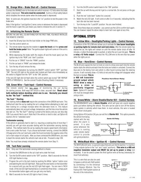
14. Blue – Horn/Siren – <strong>Control</strong> Harness<br />
The BLUE wire signals the horn to honk (or siren to chirp) once each time the remote<br />
starter starts the vehicle and each time the locks are locked or unlocked. Connect the<br />
blue wire to the factory horn wire which is often found running down the steering<br />
column. It will normally show +12 Volts at rest and the voltage will disappear when<br />
the horn is honked. This is<br />
a 400 mA transistor<br />
Positive Horn/Siren Relay<br />
ground output which<br />
MUST drive a relay if<br />
using a siren or<br />
positively triggered<br />
horn. Option #11 (section<br />
24) must be changed when<br />
using a siren.<br />
15. Brown/White – Alarm Disable/<strong>Starter</strong> Kill – <strong>Control</strong> Harness<br />
The BROWN/WHITE wire is Alarm Disable, which will give out a quick negative<br />
pulse just be<strong>for</strong>e starting the vehicle. This wire can be used to turn off the factory<br />
alarm system in vehicles which have them. In most vehicles, this wire is located<br />
in the driver’s kick panel.<br />
Using Option #19 (section 24) you can set this to <strong>Starter</strong> Kill. This option prevents<br />
the vehicle from being<br />
<strong>Starter</strong> Kill Relay<br />
started with the key<br />
when the alarm is<br />
<strong>Starter</strong> Wire<br />
<strong>Starter</strong> Wire<br />
armed. It is also<br />
From Key<br />
Cut<br />
To <strong>Starter</strong><br />
Switch<br />
Motor<br />
active whenever the<br />
87<br />
vehicle is running<br />
<strong>Remote</strong> <strong>Starter</strong><br />
Tap into Blue<br />
Brown / White<br />
IGN1 Wire from<br />
87A<br />
Wire 86 30 85<br />
<strong>Remote</strong> <strong>Starter</strong><br />
under remote starter<br />
control to provide Yellow Start Wire<br />
From <strong>Remote</strong> <strong>Starter</strong><br />
anti-grind protection.<br />
16. White/Black Wire – Ignition #3 – <strong>Control</strong> Harness<br />
The WHITE/BLACK wire, is a ground output that acts just like the Ignition 1 or Ignition<br />
2 relay outputs (active in the “run” and “crank” positions). This wire is a 400 mA<br />
negative transistor output and MUST be set up to power a relay (not<br />
included). It can be used to power the third ignition wire at the key (necessary <strong>for</strong><br />
most Ford vehicles).<br />
This is a wire that can also be used<br />
to bypass a vehicle anti-theft system<br />
by connecting it to the Universal<br />
Alarm Bypass Module. See the<br />
Factory Anti-Theft System section at<br />
the end of the instructions.<br />
Ignition 3<br />
White/Black Wire 87<br />
From<br />
87A<br />
<strong>Remote</strong> <strong>Starter</strong> 85 30<br />
To LARGE 12 Volt<br />
Constant Wire<br />
(Found in Ignition<br />
Switch Wire<br />
Harness)<br />
To Additional<br />
Ignition Wire<br />
(in vehicle)<br />
3 v3.1 2428<br />
86