MBC-120⦠- Peppas Ltd Combustion - energy controls
MBC-120⦠- Peppas Ltd Combustion - energy controls
MBC-120⦠- Peppas Ltd Combustion - energy controls

You also want an ePaper? Increase the reach of your titles
YUMPU automatically turns print PDFs into web optimized ePapers that Google loves.
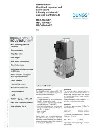
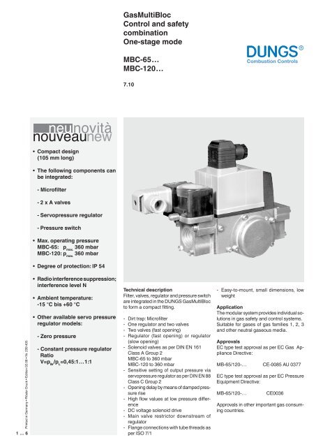
GasMultiBloc<br />
Control and safety<br />
combination<br />
One-stage mode<br />
<strong>MBC</strong>-65…<br />
<strong>MBC</strong>-120…<br />
7.10<br />
• Compact design<br />
(105 mm long)<br />
• The following components can<br />
be integrated:<br />
- Microfilter<br />
- 2 x A valves<br />
- Servopressure regulator<br />
- Pressure switch<br />
• Max. operating pressure<br />
<strong>MBC</strong>-65: p max.<br />
360 mbar<br />
<strong>MBC</strong>-120: p max.<br />
360 mbar<br />
• Degree of protection: IP 54<br />
Printed in Germany • Rösler Druck • Edition 02.08 • Nr. 239 405<br />
1 … 6<br />
• Radio interference suppression;<br />
interference level N<br />
• Ambient temperature:<br />
-15 °C bis +60 °C<br />
• Other available servo pressure<br />
regulator models:<br />
- Zero pressure<br />
- Constant pressure regulator<br />
Ratio<br />
V=p Br<br />
/p L<br />
=0,45:1…1:1<br />
Technical description<br />
Filter, valves, regulator and pressure switch<br />
are integrated in the DUNGS GasMultiBloc<br />
to form a compact fitting.<br />
- Dirt trap: Microfilter<br />
- One regulator and two valves<br />
- Two valves (fast opening)<br />
- Regulator (fast opening) or regulator<br />
(slow opening)<br />
- Solenoid valves as per DIN EN 161<br />
Class A Group 2<br />
<strong>MBC</strong>-65 to 360 mbar<br />
<strong>MBC</strong>-120 to 360 mbar<br />
- Sensitive setting of output pressure via<br />
servopressure regulator as per DIN EN 88<br />
Class C Group 2<br />
- Opening delay by means of damped pressure<br />
rise<br />
- High flow values at low pressure difference<br />
- DC voltage solenoid drive<br />
- Main valve restrictor downstream of<br />
regulator<br />
- Flange connections with tube threads as<br />
per ISO 7/1<br />
- Easy-to-mount, small dimensions, low<br />
weight<br />
Application<br />
The modular system provides individual solutions<br />
in gas safety and control systems.<br />
Suitable for gases of gas families 1, 2, 3<br />
and other neutral gaseous media.<br />
Approvals<br />
EC type test approval as per EC Gas Appliance<br />
Directive:<br />
MB-65/120-… CE-0085 AU 0377<br />
EC type test approval as per EC Pressure<br />
Equipment Directive:<br />
MB-65/120-…<br />
CE0036<br />
Approvals in other important gas consuming<br />
countries.
Functional description<br />
Gas flow<br />
1. Valves V1 and V2 are closed. Inlet<br />
pressure is applied to chamber A<br />
until valve V1 is seated.<br />
2. The min. pressure switch is connected<br />
to Chamber A by a borehole.<br />
If the inlet pressure exceeds<br />
the reference value set on the<br />
pressure switch, it switches to the<br />
automatic gas burner control.<br />
3. After a release signal from the<br />
automatic gas burner control,<br />
valves V1 and V2 open. The gas<br />
flow through chambers A, B, C<br />
and D of the GasMultiBloc is<br />
released.<br />
Dirt trap device<br />
Dirt trap device, fine-meshed filter (1)<br />
to protect the fitting.<br />
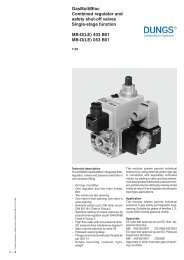
Sectional view <strong>MBC</strong>-65-DLE-S20<br />
1<br />
2<br />
3<br />
A<br />
B<br />
Pressure taps<br />
4<br />
C<br />
5<br />
6<br />
D<br />
17<br />
16<br />
15<br />
14<br />
13<br />
12<br />
11<br />
10<br />
9<br />
8<br />
7<br />
1. Microfilter<br />
2. Inlet P1<br />
3. Housing<br />
4. Spring, gas pressure regulator<br />
5. Diaphragms, gas pressure regulator<br />
6. Cover side<br />
7. Nozzle<br />
8. Outlet P3<br />
9. Main flow restrictor<br />
10. Start gas restrictor<br />
11. Damper<br />
12. Servopressure regulator<br />
13. Adjustment screw - main flow<br />
14. Reference value adjustment<br />
device - pressure regulator<br />
15. Adjustment screw - start flow<br />
16. Solenoid housing V1, V2<br />
17. Electrical connection<br />
18 Setting of opening time<br />
(only <strong>MBC</strong>-120)<br />
Operating mode of valve V1 and<br />
valve V2<br />
The plungers of valves V1 and V2 are<br />
connected to the valve plate units.<br />
On opening, the plungers pretension<br />
the closing springs. The valves open<br />
completely without limitation.<br />
Closing function<br />
When the power supply of solenoid<br />
coils of V1 and V2 is interrupted, the<br />
valves are closed within < 1s by means<br />
of pressure springs.<br />
Operating mode of servopressure<br />
regulator<br />
The servopressure regulator equalises<br />
the pressure fluctuations in the power<br />
supply. The output pressure is set at<br />
the reference value adjustment device<br />
(14). The servopressure regulator<br />
<strong>controls</strong> the pressure regulator (5) via<br />
nozzle (7).<br />
The “slow opening” function is enabled<br />
by a damped pressure increase.<br />
The opening time of <strong>MBC</strong>-120 cannot<br />
be set.<br />
With <strong>MBC</strong>-120, the opening behaviour<br />
can be adjusted at high operating pressure<br />
values.<br />
Start flow adjustment<br />
The adjustment screw (15) for the start<br />
flow restrictor (10) is closed (factory<br />
setting).<br />
The start flow can be set by opening<br />
the restrictor up to approx. 80 % of the<br />
main flow.<br />
Main flow adjustment<br />
The adjustment screw (13) for the main<br />
flow restrictor (9) is completely open (factory<br />
setting). The servopressure regulator<br />
<strong>MBC</strong>-65<br />
<strong>MBC</strong>-120<br />
keeps the output pressure upstream of<br />
the main flow restrictor constant. The<br />
burner pressure is determined when the<br />
output pressure and the main flow restrictor<br />
(9) are adjusted.<br />
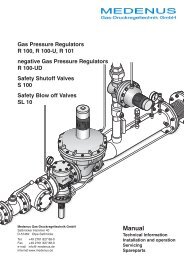
Start-up response<br />
Main gas<br />
flow<br />
Start gas<br />
flow<br />
Time<br />
1 V1 V2<br />
P 2 P 3<br />
10<br />
P 1<br />
1<br />
V1<br />
V2<br />
P 3<br />
10<br />
P 1<br />
18<br />
12<br />
12<br />
Gas pressure switch<br />
The gas pressure switch monitors the<br />
gas pressure on the inlet side; the pressure<br />
switch is preset.<br />
9<br />
9<br />
2 … 6
Specifications<br />
Nominal widths<br />
Flange with tube threads as per<br />
ISO 7/1 (DIN 2999)<br />
Max. operating pressure<br />
<strong>MBC</strong>-65...<br />
<strong>MBC</strong>-120...<br />
Rp 3/8, Rp 1/2 Rp 3/4<br />
<strong>MBC</strong>-65-… p max.<br />
360 mbar<br />
<strong>MBC</strong>-120-… p max.<br />
360 mbar<br />
Output pressure ranges<br />
P3 (p a<br />
)<br />
<strong>MBC</strong>-…-DLE S20/S22<br />
<strong>MBC</strong>-…-DLE S40/S42<br />
<strong>MBC</strong>-…-ND/S00/S02<br />
3 mbar to 15 mbar<br />
4 mbar to 37 mbar<br />
0 ± 0,2 mbar<br />
Media<br />
Ambient temperature<br />
Dirt trap device<br />
Pressure switches<br />
Pressure regulator<br />
Solenoid valve V1<br />
Solenoid valve V2<br />
Gases of gas families 1, 2, 3 and other neutral gaseous media<br />
-15 °C to +60 °C<br />
Filter with 120µm mesh width<br />
Types GW A5, GW A2, NB A2, ÜB A2 can be mounted as per DIN EN 1854.<br />
For further information, refer to datasheet GW...A2 No. 213 372 and datasheet<br />
GW...A5 No. 225 756<br />
Servopressure regulator as per DIN EN 88 Class C.<br />
Reference value spring is installed permanently (no spring replacement possible).<br />
Blow-out line over roof top must not be installed. Internal pulse tap available.<br />
Valve as per DIN 161 Class A Group 2, fast closing, fast opening<br />
Valve as per DIN 161 Class A Group 2, fast closing, fast opening<br />
Design Valves V1 and V2 Pressure regulator<br />
<strong>MBC</strong>-… -DLE fast closing slow opening<br />
<strong>MBC</strong>-… -ND fast closing slow opening, proportional regulator<br />
zero pressure regulator<br />
Measuring/ignition gas connection<br />
Voltage/frequency<br />
Electrical connection<br />
Performance/power consumption<br />
Switch-on period<br />
Degree of protection<br />
Radio interference suppression<br />
See “Pressure taps”, page 2<br />
~(AC) 50-60 Hz 220-230 V - 15 % + 10 %<br />
Preferred voltages: 110-120 VAC, 24 VDC<br />
Plug connection as per DIN EN 175301-803 for valves and pressure switches<br />
or DIN 46342 for safety extra-low voltage<br />
<strong>MBC</strong>-65... 18 VA per ~(AC) 230 V, 20 °C<br />
<strong>MBC</strong>-120... 24 VA per ~(AC) 230 V, 20 °C<br />
100 % ED<br />
IP 54 as per IEC 529 (EN 60529)<br />
Interference level N<br />
Material of gas-wetted parts<br />
Housing<br />
Diaphragms, seals<br />
Solenoid drive<br />
Aluminium<br />
NBR basis, cork<br />
Steel, brass, aluminium<br />
Installation position<br />
Vertical, with solenoid pointing upwards or lying with horizontal solenoid and<br />
their intermediate layers<br />
3 … 6
Adjustment range<br />
Application of constant<br />
pressure regulator<br />
<br />
<br />
<br />
<br />
<br />
<br />
<br />
<br />
<br />
<br />
<br />
Adjustment range<br />
Application of zero<br />
pressure regulator<br />
<br />
<br />
<br />
<br />
<br />
Adjustment instructions<br />
Rapid and simple adjustment by means of:<br />
• Adjust offset correction using setting screw on servo regulator.<br />
• Adjust maximum flow using flow restriction screw.<br />
4 … 6
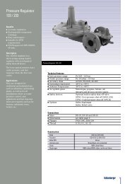
Volume flow pressure difference characteristics in steady state with microsieve<br />
<strong>MBC</strong>-65…<br />
100<br />
80<br />
60<br />
50<br />
40<br />
30<br />
20<br />
10<br />
8<br />
6<br />
5<br />
4<br />
3<br />
2<br />
1<br />
Based on +15 °C, 1013 mbar, dry<br />
0,1 0,2 0,3 0,4 0,5 0,6 0,8 1 2 3 4 5 6 7 8 910<br />
Vn ° [m 3 /h] Luft / Air / Aria dv = 1,00<br />
15<br />
<strong>MBC</strong>-120…<br />
0,2 0,3 0,4 0,50,6 0,8 1 2 3 4 5 6 7 8 910 20<br />
Vn ° [m 3 /h] Erdgas/Natural gas/Gaz Naturel/Gas metano dv = 0,65<br />
Based on +15 °C, 1013 mbar, dry<br />
f =<br />
Air density<br />
Density of gas used<br />
Gas type<br />
Natural gas<br />
City gas<br />
Liquefied gas<br />
Air<br />
Density<br />
[kg/m 3 ]<br />
0.81<br />
0.58<br />
2.08<br />
1.24<br />
dv<br />
0.65<br />
0.47<br />
1.67<br />
1.00<br />
f<br />
1.24<br />
1.46<br />
0.77<br />
1.00<br />
5 … 6<br />
V<br />
°<br />
verwendetes Gas/gas used/ gaz utilisé/gas utilizzato<br />
=<br />
°<br />
V Luft/air/air/aria<br />
x f
GasMultiBloc<br />
Control and safety combination<br />
One-stage mode<br />
<strong>MBC</strong>-65-…<br />
<strong>MBC</strong>-120-…<br />
Dimensions [mm]<br />
e<br />
d<br />
c<br />
a<br />
b<br />
f<br />
Type<br />
Rp<br />
Opening time<br />
a<br />
Dimensions [mm]<br />
b c d e<br />
f<br />
Rating/Power Consumption<br />
~(AC) 230 V; + 20 °C<br />
Weight<br />
[kg]<br />
<strong>MBC</strong>-65<br />
<strong>MBC</strong>-120<br />
Rp 1/2<br />
Rp 3/4<br />
< 1 s<br />
< 20 s<br />
105<br />
105<br />
148<br />
155<br />
31<br />
37<br />
160<br />
173<br />
226<br />
232<br />
76<br />
82<br />
18 VA<br />
24 VA<br />
1,5<br />
1,6<br />
We reserve the right to make any changes in the interest of technical progress.<br />
Head Offices and Factory<br />
Karl Dungs GmbH & Co. KG<br />
Siemensstraße 6-10<br />
D-73660 Urbach, Germany<br />
Telephone +49 (0)7181-804-0<br />
Fax +49 (0)7181-804-166<br />
Postal address<br />
Karl Dungs GmbH & Co. KG<br />
Postfach 12 29<br />
D-73602 Schorndorf, Germany<br />
e-mail info@dungs.com<br />
Internet www.dungs.com<br />
6 … 6