- Page 1: Warsaw University of Technology Fac
- Page 5 and 6: Contents 1. Introduction 1 Pages 2.
- Page 7 and 8: 1. Introduction The Adjustable Spee
- Page 9 and 10: 1. Introduction The first vector co
- Page 11 and 12: 1. Introduction algorithms are desc
- Page 13 and 14: 2.2. Mathematical Model of Inductio
- Page 15 and 16: ( ) 2.2. Mathematical Model of Indu
- Page 17 and 18: 2.2. Mathematical Model of Inductio
- Page 19 and 20: 2.3. Voltage Source Inverter (VSI)
- Page 21 and 22: 2.3. Voltage Source Inverter (VSI)
- Page 23 and 24: 2.4. Pulse Width Modulation (PWM) f
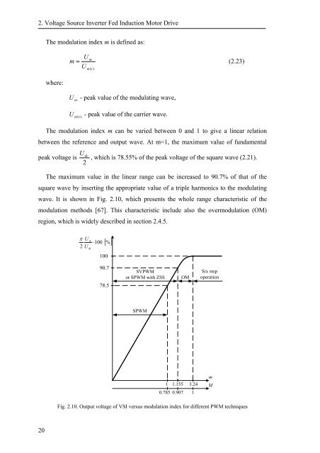
- Page 25: 2.4. Pulse Width Modulation (PWM) U
- Page 29 and 30: 2.4. Pulse Width Modulation (PWM) d
- Page 31 and 32: 2.4. Pulse Width Modulation (PWM) T
- Page 33 and 34: 2.4. Pulse Width Modulation (PWM) I
- Page 35 and 36: 2.4. Pulse Width Modulation (PWM) a
- Page 37 and 38: 2.4. Pulse Width Modulation (PWM) F
- Page 39 and 40: 2.4. Pulse Width Modulation (PWM) I
- Page 41 and 42: 2.4. Pulse Width Modulation (PWM) T
- Page 43 and 44: 2.4. Pulse Width Modulation (PWM) m
- Page 45 and 46: 2.5. Summary random modulation tech
- Page 47 and 48: 3.2. Field Oriented Control (FOC)
- Page 49 and 50: 3.2. Field Oriented Control (FOC) F
- Page 51 and 52: 3.3. Feedback Linearization Control
- Page 53 and 54: 3.3. Feedback Linearization Control
- Page 55 and 56: 3.4. Direct Flux and Torque Control
- Page 57 and 58: 3.4. Direct Flux and Torque Control
- Page 59 and 60: 3.4. Direct Flux and Torque Control
- Page 61 and 62: 3.4. Direct Flux and Torque Control
- Page 63 and 64: 3.4. Direct Flux and Torque Control
- Page 65 and 66: 3.4. Direct Flux and Torque Control
- Page 67 and 68: 3.4. Direct Flux and Torque Control
- Page 69 and 70: 3.4. Direct Flux and Torque Control
- Page 71 and 72: 3.5. Summary methods. Table 3.2 sum
- Page 73 and 74: 4.2. Structures of DTC-SVM - Review
- Page 75 and 76: 4.2. Structures of DTC-SVM - Review
- Page 77 and 78:
4.3. Analysis and Controller Design
- Page 79 and 80:
4.3. Analysis and Controller Design
- Page 81 and 82:
4.3. Analysis and Controller Design
- Page 83 and 84:
4.3. Analysis and Controller Design
- Page 85 and 86:
4.3. Analysis and Controller Design
- Page 87 and 88:
4.3. Analysis and Controller Design
- Page 89 and 90:
4.3. Analysis and Controller Design
- Page 91 and 92:
4.3. Analysis and Controller Design
- Page 93 and 94:
4.3. Analysis and Controller Design
- Page 95 and 96:
4.3. Analysis and Controller Design
- Page 97 and 98:
4.3. Analysis and Controller Design
- Page 99 and 100:
4.3. Analysis and Controller Design
- Page 101 and 102:
4.4. Speed Controller Design M L Ω
- Page 103 and 104:
4.4. Speed Controller Design the sp
- Page 105 and 106:
5. Estimation in Induction Motor Dr
- Page 107 and 108:
5.2. Estimation of Inverter Output
- Page 109 and 110:
5.2. Estimation of Inverter Output
- Page 111 and 112:
5.3. Stator Flux Vector Estimators
- Page 113 and 114:
5.3. Stator Flux Vector Estimators
- Page 115 and 116:
5.3. Stator Flux Vector Estimators
- Page 117 and 118:
5.5. Rotor Speed Estimation stator
- Page 119 and 120:
6. Configuration of the Developed I
- Page 121 and 122:
6.3. Laboratory Setup Based on DS11
- Page 123 and 124:
6.3. Laboratory Setup Based on DS11
- Page 125 and 126:
6.4. Drive Based on TMS320LF2406 Th
- Page 127 and 128:
6.4. Drive Based on TMS320LF2406 In
- Page 129 and 130:
7.2. Pulse Width Modulation Fig. 7.
- Page 131 and 132:
7.3. Flux and Torque Controllers f
- Page 133 and 134:
7.3. Flux and Torque Controllers Th
- Page 135 and 136:
7.4. DTC-SVM Control System b) Fig.
- Page 137 and 138:
7.4. DTC-SVM Control System Fig. 7.
- Page 139 and 140:
7.4. DTC-SVM Control System Fig. 7.
- Page 141 and 142:
7.4. DTC-SVM Control System Fig. 7.
- Page 143 and 144:
7.4. DTC-SVM Control System Fig. 7.
- Page 145 and 146:
8. Summary and Conclusions which ar
- Page 147 and 148:
References [1] V. Ambrozic, G.S. Bu
- Page 149 and 150:
References [26] D. Casadei, G. Serr
- Page 151 and 152:
References [54] J. Holtz, Juntao Qu
- Page 153 and 154:
References [83] R. Marino, S. Peres
- Page 155 and 156:
References [111] Y. Xue, X. Xu, T.G
- Page 157 and 158:
List of Symbols a = e j2 π 3 1 =
- Page 159 and 160:
List of symbols U , U - stator volt
- Page 161 and 162:
List of symbols ZSS - Zero Sequence
- Page 163 and 164:
Appendices for even n: π 2 1− co
- Page 165 and 166:
Appendices Fig. A.2.2. Model of inv
- Page 167 and 168:
Appendices A.3. Data and Parameters
- Page 169 and 170:
Appendices A.4. Equipment Table A.4
- Page 171 and 172:
Appendices Fig. A.5.1. Block diagra
- Page 173 and 174:
Appendices A.6. Processor TMS320FL2
- Page 175:
Appendices • 40 Individually Prog


![[TCP] Opis układu - Instytut Sterowania i Elektroniki Przemysłowej ...](https://img.yumpu.com/23535443/1/184x260/tcp-opis-ukladu-instytut-sterowania-i-elektroniki-przemyslowej-.jpg?quality=85)
