

Space Vector Modulated – Direct Torque Controlled (DTC – SVM ...
Space Vector Modulated – Direct Torque Controlled (DTC – SVM ...
Space Vector Modulated – Direct Torque Controlled (DTC – SVM ...

You also want an ePaper? Increase the reach of your titles
YUMPU automatically turns print PDFs into web optimized ePapers that Google loves.
2. Voltage Source Inverter Fed Induction Motor Drive<br />
cycles the switching sequence is deterministic. In RPWM methods the switching<br />
frequency or the switching sequence change randomly.<br />
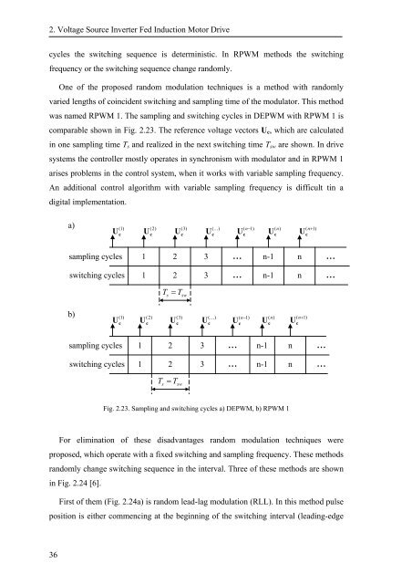
One of the proposed random modulation techniques is a method with randomly<br />
varied lengths of coincident switching and sampling time of the modulator. This method<br />
was named RPWM 1. The sampling and switching cycles in DEPWM with RPWM 1 is<br />
comparable shown in Fig. 2.23. The reference voltage vectors U c , which are calculated<br />
in one sampling time T s and realized in the next switching time T sw are shown. In drive<br />
systems the controller mostly operates in synchronism with modulator and in RPWM 1<br />
arises problems in the control system, when it works with variable sampling frequency.<br />
An additional control algorithm with variable sampling frequency is difficult tin a<br />
digital implementation.<br />
a)<br />
(1)<br />
U c<br />
(2)<br />
U c<br />
(3)<br />
U c<br />
(K)<br />
U c<br />
( n−1)<br />
U c<br />
(n)<br />
U c<br />
( n+1)<br />
U c<br />
sampling cycles 1 2 3 ... n-1 n ...<br />
switching cycles 1 2 3 ... n-1 n ...<br />
T<br />
s<br />
= T sw<br />
b)<br />
(1)<br />
U c<br />
(2)<br />
U c<br />
(3)<br />
U c<br />
(K)<br />
U c<br />
( n−1)<br />
U c<br />
(n)<br />
U c<br />
( n+1)<br />
U c<br />
sampling cycles 1 2 3 ... n-1 n<br />
switching cycles 1 2 3 ... n-1 n ...<br />
T<br />
s<br />
= T sw<br />
...<br />
Fig. 2.23. Sampling and switching cycles a) DEPWM, b) RPWM 1<br />
For elimination of these disadvantages random modulation techniques were<br />
proposed, which operate with a fixed switching and sampling frequency. These methods<br />
randomly change switching sequence in the interval. Three of these methods are shown<br />
in Fig. 2.24 [6].<br />
First of them (Fig. 2.24a) is random lead-lag modulation (RLL). In this method pulse<br />
position is either commencing at the beginning of the switching interval (leading-edge<br />
36


![[TCP] Opis układu - Instytut Sterowania i Elektroniki Przemysłowej ...](https://img.yumpu.com/23535443/1/184x260/tcp-opis-ukladu-instytut-sterowania-i-elektroniki-przemyslowej-.jpg?quality=85)
