

Space Vector Modulated – Direct Torque Controlled (DTC – SVM ...
Space Vector Modulated – Direct Torque Controlled (DTC – SVM ...
Space Vector Modulated – Direct Torque Controlled (DTC – SVM ...

You also want an ePaper? Increase the reach of your titles
YUMPU automatically turns print PDFs into web optimized ePapers that Google loves.
2. Voltage Source Inverter Fed Induction Motor Drive<br />
The main disadvantage of the RPWM 1 method (Fig. 2.23b) is variable switching<br />
frequency. For elimination of this disadvantage RPWM 2 [119] was proposed, which<br />
operates with fixed sampling frequency and variable switching frequency. The principle<br />
of this method is shown in Fig. 2.25.<br />
T s<br />
(1)<br />
U c<br />
(2)<br />
U c<br />
(3)<br />
U c<br />
(K)<br />
U c<br />
( n−1)<br />
U c<br />
(n)<br />
U c<br />
( n+1)<br />
U c<br />
sampling cycles<br />
switching cycles<br />
∆t<br />
1 2 3 ... n-1 n ...<br />
1 2 3 ... n-1 n<br />
T sw<br />
...<br />
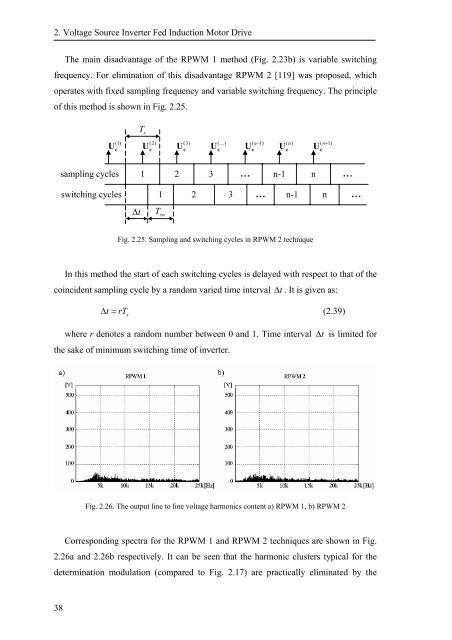
Fig. 2.25. Sampling and switching cycles in RPWM 2 technique<br />
In this method the start of each switching cycles is delayed with respect to that of the<br />
coincident sampling cycle by a random varied time interval<br />
∆ t . It is given as:<br />
∆ t = rT s<br />
(2.39)<br />
where r denotes a random number between 0 and 1. Time interval<br />
the sake of minimum switching time of inverter.<br />
∆ t is limited for<br />
Fig. 2.26. The output line to line voltage harmonics content a) RPWM 1, b) RPWM 2<br />
Corresponding spectra for the RPWM 1 and RPWM 2 techniques are shown in Fig.<br />
2.26a and 2.26b respectively. It can be seen that the harmonic clusters typical for the<br />
determination modulation (compared to Fig. 2.17) are practically eliminated by the<br />
38


![[TCP] Opis układu - Instytut Sterowania i Elektroniki Przemysłowej ...](https://img.yumpu.com/23535443/1/184x260/tcp-opis-ukladu-instytut-sterowania-i-elektroniki-przemyslowej-.jpg?quality=85)
