

Space Vector Modulated – Direct Torque Controlled (DTC – SVM ...
Space Vector Modulated – Direct Torque Controlled (DTC – SVM ...
Space Vector Modulated – Direct Torque Controlled (DTC – SVM ...

Create successful ePaper yourself
Turn your PDF publications into a flip-book with our unique Google optimized e-Paper software.
2. Voltage Source Inverter Fed Induction Motor Drive<br />
In the hexagon trajectory part only active vectors are used. The duration of these<br />
vectors t 1 and t 2 are obtained from trigonometrical relationships and can be expressed in<br />
the following equations:<br />
3 cosα<br />
− sinα<br />
t 1<br />
= T s<br />
(2.37a)<br />
3 cosα<br />
+ sinα<br />
t<br />
= −<br />
(2.37b)<br />
2<br />
Ts<br />
t1<br />
t 0<br />
= t 7<br />
= 0<br />
(2.37c)<br />
The output voltage waveform is given approximately by linear segments for the<br />
hexagon trajectory and sinusoidal segments for the circular trajectory. Boundary of the<br />
segments is determined by a crossover angle θ which depends on the reference voltage<br />
value. As known from Fig. 2.21 the upper limit in mode I is when θ = 0°. Then the<br />
voltage trajectory is fully on the hexagon. The fundamental peak value generated in this<br />
way voltage is 95% of the peak voltage of the square wave [75]. It gives modulation<br />
index M = 0.952.<br />
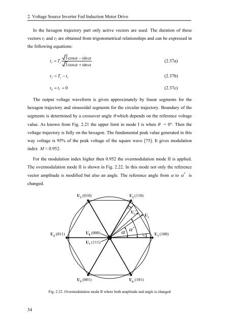
For the modulation index higher then 0.952 the overmodulation mode II is applied.<br />
The overmodulation mode II is shown in Fig. 2.22. In this mode not only the reference<br />
vector amplitude is modified but also an angle. The reference angle from α to α *<br />
changed.<br />
is<br />
U 3<br />
(010)<br />
U 2<br />
(110)<br />
α h<br />
U c<br />
*<br />
U c<br />
U 4<br />
(011)<br />
U 0<br />
(000)<br />
α<br />
∗<br />
α<br />
α h<br />
U 1<br />
(100)<br />
U 7<br />
(111)<br />
U 5<br />
(001) U 6<br />
(101)<br />
Fig. 2.22. Overmodulation mode II where both amplitude and angle is changed<br />
34


![[TCP] Opis układu - Instytut Sterowania i Elektroniki Przemysłowej ...](https://img.yumpu.com/23535443/1/184x260/tcp-opis-ukladu-instytut-sterowania-i-elektroniki-przemyslowej-.jpg?quality=85)
