

Space Vector Modulated – Direct Torque Controlled (DTC – SVM ...
Space Vector Modulated – Direct Torque Controlled (DTC – SVM ...
Space Vector Modulated – Direct Torque Controlled (DTC – SVM ...

You also want an ePaper? Increase the reach of your titles
YUMPU automatically turns print PDFs into web optimized ePapers that Google loves.
2. Voltage Source Inverter Fed Induction Motor Drive<br />
range between this point and six-step mode is called overmodulation. This part of the<br />
modulation techniques is not so important in vector controlled drives methods for the<br />
sake of big distortion current and torque. For example, the overmodulation can be<br />
applied in drives working in open loop control mode to increase the value of inverter<br />
output voltage.<br />
The overmodulation has been widely discussed in the literature [16, 33, 55, 75, 89].<br />
Some of methods are proposed as extensions of the carrier based modulation and others<br />
as extensions of space vector modulation. In the carrier based methods overmodulation<br />
algorithm is realized by increasing reference voltage beyond the amplitude of the<br />
triangular carrier signal. In this case some switching cycles are omitted and each phase<br />
is clamped to one of the dc busses.<br />
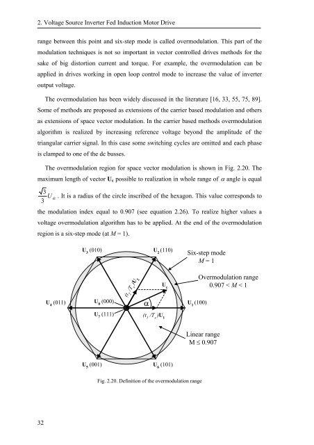
The overmodulation region for space vector modulation is shown in Fig. 2.20. The<br />
maximum length of vector U c possible to realization in whole range of α angle is equal<br />
3<br />
3<br />
U dc<br />
. It is a radius of the circle inscribed of the hexagon. This value corresponds to<br />
the modulation index equal to 0.907 (see equation 2.26). To realize higher values a<br />
voltage overmodulation algorithm has to be applied. At the end of the overmodulation<br />
region is a six-step mode (at M = 1).<br />
U 3<br />
(010)<br />
U 2<br />
(110)<br />
Six-step mode<br />
M = 1<br />
U 4<br />
(011)<br />
U 0<br />
(000) U 1<br />
(100)<br />
U 7<br />
(111)<br />
(t 2<br />
/T s<br />
)U 2<br />
α<br />
(t 1<br />
/T s<br />
)U 1<br />
U c<br />
Overmodulation range<br />
0.907 < M < 1<br />
Linear range<br />
M ≤ 0.907<br />
U 5<br />
(001) U 6<br />
(101)<br />
Fig. 2.20. Definition of the overmodulation range<br />
32


![[TCP] Opis układu - Instytut Sterowania i Elektroniki Przemysłowej ...](https://img.yumpu.com/23535443/1/184x260/tcp-opis-ukladu-instytut-sterowania-i-elektroniki-przemyslowej-.jpg?quality=85)
