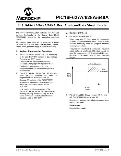
PIC16F627A/628A/648A Rev. A Silicon/Data Sheet Errata
PIC16F627A/628A/648A Rev. A Silicon/Data Sheet Errata
PIC16F627A/628A/648A Rev. A Silicon/Data Sheet Errata

You also want an ePaper? Increase the reach of your titles
YUMPU automatically turns print PDFs into web optimized ePapers that Google loves.
<strong>PIC16F627A</strong>/<strong>628A</strong>/<strong>648A</strong><br />
<strong>PIC16F627A</strong>/<strong>628A</strong>/<strong>648A</strong> <strong>Rev</strong>. A <strong>Silicon</strong>/<strong>Data</strong> <strong>Sheet</strong> <strong>Errata</strong><br />
The <strong>PIC16F627A</strong>/<strong>628A</strong>/<strong>648A</strong> parts you have received<br />
conform functionally to the Device <strong>Data</strong> <strong>Sheet</strong><br />
(DS40044A), except for the anomalies described<br />
below.<br />
All problems listed here will be addressed in future<br />
revisions of the <strong>PIC16F627A</strong>/<strong>628A</strong>/<strong>648A</strong> silicon.<br />
Where noted, problems apply to listed revision only.<br />
1. Module: Programming Operations<br />
1. <strong>PIC16F627A</strong>/<strong>628A</strong> silicon <strong>Rev</strong>. A3. Accessing<br />
of the data EEPROM memory in Low Voltage<br />
Programming (LVP) mode.<br />
- The data EEPROM memory cannot be<br />
accessed when programming in LVP mode.<br />
- The Flash program memory and the<br />
configuration bits can be accessed properly<br />
in LVP mode.<br />
2. <strong>PIC16F627A</strong>/<strong>628A</strong> silicon <strong>Rev</strong>. A3 and A4.<br />
Flash program memory can only be<br />
programmed with a VDD of 4.5V-5.5V.<br />
- <strong>Rev</strong>ision A5 and later of the <strong>PIC16F627A</strong>/<br />
<strong>628A</strong> silicon, the Flash program memory is<br />
able to be programmed with a VDD of<br />
2.0V-5.5V.<br />
- In all current and future revisions of the<br />
<strong>PIC16F627A</strong>/<strong>628A</strong> silicon, the Flash program<br />
memory can only be erased using the Bulk<br />
Erase command. The Bulk Erase function<br />
requires a VDD of 4.5V-5.5V.<br />
2. Module: EC Clock<br />
1. PIC16F<strong>648A</strong> <strong>Silicon</strong> <strong>Rev</strong>. A1.<br />
When using the EC OSC mode at frequencies<br />
>4 MHz and temperatures >85°C, the part may<br />
execute incorrectly from the program memory<br />
causing malfunction.<br />
This problem only affects E-temp parts. Industrial<br />
grade parts are unaffected. HS mode should be<br />
used for frequencies >4 MHz at extended temps.<br />
All other clock modes work to their specified<br />
ranges.<br />
85°C<br />
Temp<br />
4 MHz<br />
Speed<br />
Affected Location<br />
Use<br />
HS mode<br />
2. <strong>PIC16F627A</strong>/<strong>628A</strong> <strong>Silicon</strong> revision A3, A4 and<br />
A5. PIC16F<strong>648A</strong> <strong>Silicon</strong> revision A1.<br />
Unexpected program execution may occur when<br />
waking from Sleep.<br />
Work around<br />
Use HS Clock mode.<br />
© 2003 Microchip Technology Inc. DS80151G-page 1
<strong>PIC16F627A</strong>/<strong>628A</strong>/<strong>648A</strong><br />
3. Module: <strong>Data</strong> EEPROM Memory<br />
1. PIC16F<strong>648A</strong> <strong>Silicon</strong> revision A1 and<br />
<strong>PIC16F627A</strong>/<strong>628A</strong> silicon revision A3, A4 and<br />
A5.<br />
Note:<br />
This problem is corrected in PIC16F<strong>648A</strong><br />
<strong>Rev</strong>. A3 and <strong>PIC16F627A</strong>/<strong>628A</strong> <strong>Rev</strong>. A6.<br />
Unexpected program execution may occur during<br />
data EEPROM write cycles.<br />
Work around<br />
Execute a SLEEP instruction immediately after<br />
setting the EECON1 WR bit and allow the EEIF to<br />
wake the processor from Sleep. This requires the<br />
PEIE bit of the INTCON register and the EEIE bit<br />
of the PIE1 register to be set. All other interrupt<br />
enables must be cleared so that only the EE write<br />
completion will wake the processor.<br />
Note: Most peripherals suspend operation<br />
during Sleep. Other precautions may be<br />
necessary to ensure all peripheral<br />
operations are complete or in a safe halted<br />
mode before beginning an EEPROM<br />
write.<br />
The following example assumes that the desired<br />
address is present in the EEADR register and the<br />
desired data to be written is in the EEDATA register:<br />
EXAMPLE 1:<br />
DATA EEPROM WRITE CODE<br />
EXAMPLE<br />
BANKSEL 0X00 ;select Bank0<br />
BCF PIR1, EEIF ;ensure write complete<br />
;flag is clear<br />
BANKSEL 0x80 ;change to Bank1<br />
MOVLW 1
<strong>PIC16F627A</strong>/<strong>628A</strong>/<strong>648A</strong><br />
Clarifications/Corrections to the <strong>Data</strong><br />
<strong>Sheet</strong>:<br />
In the Device <strong>Data</strong> <strong>Sheet</strong> (DS40044A), the following<br />
clarifications and corrections should be noted.<br />
1. Module: Instruction Set (SUBWF)<br />
Example 1: (SUBWF) changes;<br />
From: Z = DC = 1<br />
To: DC = 1<br />
Z = 0<br />
2. Module: Timing Diagrams and<br />
Specifications<br />
1. In Section 17.6, Electrical Specifications, Table<br />
17-4, External Clock Timing Requirements,<br />
External CLKIN Frequency and External CLKIN<br />
Period conditions should reflect “HS, EC Osc<br />
mode”. Minimum Instruction Cycle Time (TCY) is<br />
200 nsec.<br />
TABLE 17-4:<br />
Parameter<br />
No.<br />
EXTERNAL CLOCK TIMING REQUIREMENTS<br />
Sym Characteristic Min Typ† Max Units Conditions<br />
FOSC External CLKIN Frequency (1) DC — 4 MHz XT and RC Osc mode,<br />
VDD = 5.0V<br />
DC — 20 MHz HS, EC Osc mode<br />
DC — 200 kHz LP Osc mode<br />
Oscillator Frequency (1) — — 4 MHz RC Osc mode, VDD = 5.0V<br />
0.1 — 4 MHz XT Osc mode<br />
1<br />
—<br />
—<br />
—<br />
20<br />
200<br />
MHz<br />
kHz<br />
HS Osc mode<br />
LP Osc mode<br />
— 4 — MHz INTOSC mode (fast)<br />
— 37 — kHz INTOSC mode (slow)<br />
1 TOSC External CLKIN Period (1) 250 — — ns XT and RC Osc mode<br />
50 — — ns HS, EC Osc mode<br />
5 — — µs LP Osc mode<br />
Oscillator Period (1) 250 — — ns RC Osc mode<br />
250 — 10,000 ns XT Osc mode<br />
50 — 1,000 ns HS Osc mode<br />
5 — — µs LP Osc mode<br />
— 250 — ns INTOSC mode (fast)<br />
— 27 — µs INTOSC mode (slow)<br />
2 TCY Instruction Cycle Time 200 TCY DC ns TCY = 4/FOSC<br />
3 TOSL,<br />
TOSH<br />
External CLKIN (OSC1) High<br />
External CLKIN Low<br />
100* — — ns XT oscillator, TOSC L/H duty<br />
cycle<br />
4 RC External Biased RC<br />
10 kHz* — 4 MHz — VDD = 5.0V<br />
Frequency<br />
* These parameters are characterized but not tested.<br />
† <strong>Data</strong> in “Typ” column is at 5.0V, 25°C unless otherwise stated. These parameters are for design guidance<br />
only and are not tested.<br />
Note 1: Instruction cycle period (TCY) equals four times the input oscillator time-based period. All specified values<br />
are based on characterization data for that particular oscillator type under standard operating conditions<br />
with the device executing code. Exceeding these specified limits may result in an unstable oscillator<br />
operation and/or higher than expected current consumption. All devices are tested to operate at “Min”<br />
values with an external clock applied to the OSC1 pin. When an external clock input is used, the “Max”<br />
cycle time limit is “DC” (no clock) for all devices.<br />
© 2003 Microchip Technology Inc. DS80151G-page 3
<strong>PIC16F627A</strong>/<strong>628A</strong>/<strong>648A</strong><br />
2. Table 17.2, parameter D020. Maximum Powerdown<br />
Base Current (IPD) should be 2.7 µA at<br />
5.0V. WDT current should be 17 µA at 5.0V, as<br />
shown in bold in Table 17.2.<br />
3. Table 17.2 and 17.3 for XT oscillator supply<br />
currents (IDD) are changed, as shown in bold in<br />
Table 17.2 and 17.3.<br />
17.2 DC Characteristics: <strong>PIC16F627A</strong>/<strong>628A</strong>/<strong>648A</strong> (Industrial)<br />
PIC16LF627A/<strong>628A</strong>/<strong>648A</strong> (Industrial)<br />
Param<br />
No.<br />
Supply Voltage (VDD)<br />
LF and F Device<br />
Characteristics<br />
Standard Operating Conditions (unless otherwise stated)<br />
Operating temperature -40°C ≤ TA ≤ +85°C for industrial<br />
Min† Typ Max Units<br />
LF 2.0 — 5.5 V —<br />
D001<br />
LF/F 3.0 — 5.5 V —<br />
Power-down Base Current (IPD)<br />
VDD<br />
Conditions<br />
Note<br />
LF — 0.1 0.80 µA 2.0 WDT, BOR, Comparators, VREF and<br />
D020<br />
— 0.1 0.85 µA 3.0 T1OSC: disabled<br />
LF/F<br />
— 0.2 2.7 µA 5.0<br />
Peripheral Module Current (∆IMOD) (1)<br />
D021<br />
D022<br />
D023<br />
D024<br />
D025<br />
Supply Current (IDD)<br />
D010<br />
D011<br />
D012<br />
LF — 1 2.0 µA 2.0 WDT Current<br />
LF/F<br />
LF/F<br />
— 2 3.4 µA 3.0<br />
— 9 17.0 µA 5.0<br />
— 32 TBD µA 4.5 BOR Current<br />
— 33 TBD µA 5.0<br />
LF — 15 TBD µA 2.0 Comparator Current<br />
LF/F<br />
— 27 TBD µA 3.0<br />
— 49 TBD µA 5.0<br />
LF — 34 TBD µA 2.0 VREF Current<br />
LF/F<br />
— 50 TBD µA 3.0<br />
— 80 TBD µA 5.0<br />
LF — 1.2 2.0 µA 2.0 T1OSC Current<br />
LF/F<br />
— 1.3 2.2 µA 3.0<br />
— 1.8 2.9 µA 5.0<br />
LF — 12 15 µA 2.0 FOSC = 32 kHz<br />
— 21 25 µA 3.0 LP Oscillator Mode<br />
LF/F<br />
— 38 48 µA 5.0<br />
LF — 130 190 µA 2.0 FOSC = 1 MHz<br />
— 220 340 µA 3.0 XT Oscillator Mode<br />
LF/F<br />
— 370 520 µA 5.0<br />
LF — 270 350 µA 2.0 FOSC = 4 MHz<br />
— 430 600 µA 3.0 XT Oscillator Mode<br />
LF/F<br />
— 780 995 µA 5.0<br />
D013<br />
LF/F<br />
— 2.6 2.9 mA 4.5 FOSC = 20 MHz<br />
— 3 3.3 mA 5.0 HS Oscillator Mode<br />
Note 1: The “∆“ current is the additional current consumed when this peripheral is enabled. This current should be added to the<br />
base IDD or IPD measurement. Max values should be used when calculating total current consumption.<br />
DS80151G-page 4<br />
© 2003 Microchip Technology Inc.
<strong>PIC16F627A</strong>/<strong>628A</strong>/<strong>648A</strong><br />
17.3 DC Characteristics: DC Characteristics: <strong>PIC16F627A</strong>/<strong>628A</strong>/<strong>648A</strong> (Extended)<br />
Standard Operating Conditions (unless otherwise stated)<br />
Operating temperature -40°C ≤ TA ≤ +85°C for industrial<br />
Param LF and F Device<br />
Conditions<br />
Min Typ Max Units<br />
No. Characteristics<br />
VDD<br />
Note<br />
Supply Voltage (VDD)<br />
D001 — 3.0 — 5.5 V —<br />
Power-down Base Current (IPD)<br />
D020E — — 0.1 TBD µA 3.0 WDT, BOR, Comparators, VREF,<br />
— 0.2 TBD µA 5.0 and T1OSC: disabled<br />
Peripheral Module Current (∆IMOD) (1)<br />
D021E — — 2 TBD µA 3.0 WDT Current<br />
— 9 TBD µA 5.0<br />
D022E — — 32 TBD µA 4.5 BOR Current<br />
— 33 TBD µA 5.0<br />
D023E — — 27 TBD µA 3.0 Comparator Current<br />
— 49 TBD µA 5.0<br />
D024E — — 50 TBD µA 3.0 VREF Current<br />
— 83 TBD µA 5.0<br />
D025E — — 1.3 TBD µA 3.0 T1OSC Current<br />
— 1.8 TBD µA 5.0<br />
Supply Current (IDD)<br />
D010E — — 21 TBD µA 3.0 FOSC = 32 kHz<br />
— 38 TBD µA 5.0 LP Oscillator mode<br />
D011E — — 220 TBD µA 3.0 FOSC = 1 MHz<br />
— 370 TBD µA 5.0 XT Oscillator mode<br />
D012E — — 430 TBD µA 3.0 FOSC = 4 MHz<br />
— 780 TBD µA 5.0 XT Oscillator mode<br />
D013E — — 2.6 TBD µA 4.5 FOSC = 20 MHz<br />
— 3 TBD µA 5.0 HS Oscillator mode<br />
Note 1: The “∆“ current is the additional current consumed when this peripheral is enabled. This current should be<br />
added to the base IDD or IPD measurement. Max values should be used when calculating total current<br />
consumption.<br />
© 2003 Microchip Technology Inc. DS80151G-page 5
<strong>PIC16F627A</strong>/<strong>628A</strong>/<strong>648A</strong><br />
3. Module: Pin Diagrams<br />
On page 2, Pin Diagrams, Pin 1 of 28-pin QFN<br />
package should be labeled: RA5/MCLR/VPP.<br />
28-PIN QFN<br />
RA4/T0CKI/CMP2<br />
RA3/AN3/CMP1<br />
RA2/AN2/VREF<br />
NC<br />
NC<br />
RA1/AN1<br />
RA0/AN0<br />
RA5/MCLR/VPP<br />
VSS<br />
VSS<br />
RB0/INT<br />
28<br />
27<br />
26<br />
25<br />
24<br />
23<br />
1<br />
2<br />
3<br />
4<br />
5<br />
6<br />
7<br />
8<br />
9<br />
10<br />
11<br />
12<br />
13<br />
22<br />
21<br />
20<br />
19<br />
18<br />
17<br />
16<br />
1415<br />
RA7/OSC1/CLKIN<br />
RA6/OSC2/CLKOUT<br />
VDD<br />
VDD<br />
RB7/T1OSI/PGD<br />
RB6/T1OSO/T1CKI/PGC<br />
RB1/RX/DT<br />
RB2/TX/CK<br />
RB3/CCP1<br />
RB4/PGM<br />
RB5<br />
NC<br />
NC<br />
NC<br />
NC<br />
NC<br />
<strong>PIC16F627A</strong>/<strong>628A</strong><br />
PIC16F<strong>648A</strong><br />
NC<br />
4. Module: I/O Ports<br />
In Figure 5-4, the diode between VDD and the RA4<br />
pin should be deleted.<br />
FIGURE 5-4: BLOCK DIAGRAM OF THE RA4/TOCKI PIN<br />
<strong>Data</strong><br />
Bus<br />
WR<br />
PORTA<br />
D<br />
Q<br />
CK Q<br />
<strong>Data</strong> Latch<br />
Comparator Output<br />
Comparator Mode = 110 (CMCON Reg.)<br />
1<br />
0<br />
WR<br />
TRISA<br />
D<br />
CK<br />
Q<br />
Q<br />
N<br />
RA4 Pin<br />
TRIS Latch<br />
VSS<br />
VSS<br />
RD TRISA<br />
Schmitt Trigger<br />
Input Buffer<br />
Q<br />
D<br />
EN<br />
RD PORTA<br />
TMR0 Clock Input<br />
DS80151G-page 6<br />
© 2003 Microchip Technology Inc.
<strong>PIC16F627A</strong>/<strong>628A</strong>/<strong>648A</strong><br />
5. Module: Timer1<br />
In Register 7-1, the TMR1ON bit description<br />
should be changed as follows:<br />
Bit 0 TMR1ON: Timer1 on bit<br />
1 = Enables Timer1<br />
0 = Stops Timer1<br />
6. Module: <strong>Data</strong> EEPROM Memory<br />
Example 13-4 should be replaced with the<br />
following example:<br />
EXAMPLE 13-4:<br />
DATA EEPROM REFRESH ROUTINE<br />
BANKSEL 0X80 ;select Bank1<br />
CLRF EEADR ;start at address 0<br />
BCF INTCON, GIE ;disable interrupts<br />
BSF EECON1, WREN ;enable EE writes<br />
Loop<br />
BSF EECON1, RD ;retrieve data into EEDATA<br />
MOVLW 0x55 ;first step of ...<br />
MOVWF EECON2 ;... required sequence<br />
MOVLW 0xAA ;second step of ...<br />
MOVWF EECON2 ;... required sequence<br />
BSF EECON1, WR ;start write sequence<br />
BTFSC EECON1, WR ;wait for write complete<br />
GOTO $ - 1<br />
#IFDEF __16F<strong>648A</strong><br />
;256 bytes in 16F<strong>648A</strong><br />
INCFSZ EEADR, f ;test for end of memory<br />
#ELSE<br />
;128 bytes in 16F627A/<strong>628A</strong><br />
INCF EEADR, f ;next address<br />
BTFSS EEADR, 7 ;test for end of memory<br />
#ENDIF<br />
;end of conditional assembly<br />
GOTO Loop ;repeat for all locations<br />
BCF EECON1, WREN ;disable EE writes<br />
BSF INTCON, GIE ;enable interrupts (optional)<br />
© 2003 Microchip Technology Inc. DS80151G-page 7
<strong>PIC16F627A</strong>/<strong>628A</strong>/<strong>648A</strong><br />
APPENDIX A:<br />
<strong>Rev</strong>. A Document (2/12/03)<br />
REVISION HISTORY<br />
First revision of this document.<br />
<strong>Rev</strong>. B Document (3/26/03)<br />
Added 4.5V-5.5V VDD programming requirement on<br />
<strong>Rev</strong>. A2, A3 & A4 silicon.<br />
<strong>Rev</strong>. C Document (5/13/03)<br />
Added Item 1 to Clarifications/Corrections Section;<br />
Instruction Set, Example 1: (SUBWF).<br />
<strong>Rev</strong>. D Document (7/10/03)<br />
<strong>Rev</strong>ised document title.<br />
Item 1: Added Module 2: EC Clock for PIC16F<strong>648A</strong><br />
silicon. Clarifications/Corrections to the <strong>Data</strong> <strong>Sheet</strong>,<br />
Added Module 2: Timing Diagrams and Specifications,<br />
Table 17-4.<br />
Item 2: Added correction to 28-Pin QFN package,<br />
Pin 1.<br />
<strong>Rev</strong>. E Document (8/15/03)<br />
Module 2: EC Clock: Added Item 2: “<strong>PIC16F627A</strong>/<br />
<strong>628A</strong> <strong>Silicon</strong> revision A1, A2, A3 and A4. PIC16F<strong>648A</strong><br />
<strong>Silicon</strong> revision A1”.<br />
Added Module 3: <strong>Data</strong> EEPROM Memory, Item 1.<br />
Clarifications/Corrections to the <strong>Data</strong> <strong>Sheet</strong>: Added<br />
Module 4: I/O Ports, Module 5: Timer1 and Module 6:<br />
<strong>Data</strong> EEPROM Memory.<br />
<strong>Rev</strong>. F Document (9/03/03)<br />
Module 1: Corrections to Item 2. Module 2: Corrections<br />
to Item 2. Module 3: Corrections to Item 1.<br />
Clarifications/Corrections to the <strong>Data</strong> <strong>Sheet</strong>: Module 2:<br />
Timing Diagrams and Specifications, added Item 2,<br />
corrections to Section 17.2, parameter D020.<br />
<strong>Rev</strong>. G Document (12/12/03)<br />
<strong>Rev</strong>ise second paragraph, first page. Module 3, Item 1:<br />
Add note. Clarifications/Corrections to the <strong>Data</strong> <strong>Sheet</strong>:<br />
Module 2: Corrections to Item 2 and Table 17.2. Module<br />
2: Added item 3 and corrections to Table 17.2 and 17.3.<br />
Module 4: Add Figure 5-4 from <strong>Data</strong> <strong>Sheet</strong>. Module 6:<br />
Corrections to Example 13-4.<br />
DS80151G-page 8<br />
© 2003 Microchip Technology Inc.
Note the following details of the code protection feature on Microchip devices:<br />
• Microchip products meet the specification contained in their particular Microchip <strong>Data</strong> <strong>Sheet</strong>.<br />
• Microchip believes that its family of products is one of the most secure families of its kind on the market today, when used in the<br />
intended manner and under normal conditions.<br />
• There are dishonest and possibly illegal methods used to breach the code protection feature. All of these methods, to our<br />
knowledge, require using the Microchip products in a manner outside the operating specifications contained in Microchip's <strong>Data</strong><br />
<strong>Sheet</strong>s. Most likely, the person doing so is engaged in theft of intellectual property.<br />
• Microchip is willing to work with the customer who is concerned about the integrity of their code.<br />
• Neither Microchip nor any other semiconductor manufacturer can guarantee the security of their code. Code protection does not<br />
mean that we are guaranteeing the product as “unbreakable.”<br />
Code protection is constantly evolving. We at Microchip are committed to continuously improving the code protection features of our<br />
products. Attempts to break microchip’s code protection feature may be a violation of the Digital Millennium Copyright Act. If such acts<br />
allow unauthorized access to your software or other copyrighted work, you may have a right to sue for relief under that Act.<br />
Information contained in this publication regarding device<br />
applications and the like is intended through suggestion only<br />
and may be superseded by updates. It is your responsibility to<br />
ensure that your application meets with your specifications.<br />
No representation or warranty is given and no liability is<br />
assumed by Microchip Technology Incorporated with respect<br />
to the accuracy or use of such information, or infringement of<br />
patents or other intellectual property rights arising from such<br />
use or otherwise. Use of Microchip’s products as critical components<br />
in life support systems is not authorized except with<br />
express written approval by Microchip. No licenses are conveyed,<br />
implicitly or otherwise, under any intellectual property<br />
rights.<br />
Trademarks<br />
The Microchip name and logo, the Microchip logo, Accuron,<br />
dsPIC, KEELOQ, MPLAB, PIC, PICmicro, PICSTART,<br />
PRO MATE and PowerSmart are registered trademarks of<br />
Microchip Technology Incorporated in the U.S.A. and other<br />
countries.<br />
AmpLab, FilterLab, microID, MXDEV, MXLAB, PICMASTER,<br />
SEEVAL, SmartShunt and The Embedded Control Solutions<br />
Company are registered trademarks of Microchip Technology<br />
Incorporated in the U.S.A.<br />
Application Maestro, dsPICDEM, dsPICDEM.net,<br />
dsPICworks, ECAN, ECONOMONITOR, FanSense,<br />
FlexROM, fuzzyLAB, In-Circuit Serial Programming, ICSP,<br />
ICEPIC, microPort, Migratable Memory, MPASM, MPLIB,<br />
MPLINK, MPSIM, PICkit, PICDEM, PICDEM.net, PowerCal,<br />
PowerInfo, PowerMate, PowerTool, rfLAB, rfPIC, Select<br />
Mode, SmartSensor, SmartTel and Total Endurance are<br />
trademarks of Microchip Technology Incorporated in the<br />
U.S.A. and other countries.<br />
Serialized Quick Turn Programming (SQTP) is a service mark<br />
of Microchip Technology Incorporated in the U.S.A.<br />
All other trademarks mentioned herein are property of their<br />
respective companies.<br />
© 2003, Microchip Technology Incorporated, Printed in the<br />
U.S.A., All Rights Reserved.<br />
Printed on recycled paper.<br />
Microchip received ISO/TS-16949:2002 quality system certification for<br />
its worldwide headquarters, design and wafer fabrication facilities in<br />
Chandler and Tempe, Arizona and Mountain View, California in October<br />
2003 . The Company’s quality system processes and procedures are<br />
for its PICmicro ® 8-bit MCUs, KEELOQ ® code hopping devices, Serial<br />
EEPROMs, microperipherals, non-volatile memory and analog<br />
products. In addition, Microchip’s quality system for the design and<br />
manufacture of development systems is ISO 9001:2000 certified.<br />
© 2003 Microchip Technology Inc. DS80151G-page 9
WORLDWIDE SALES AND SERVICE<br />
AMERICAS<br />
Corporate Office<br />
2355 West Chandler Blvd.<br />
Chandler, AZ 85224-6199<br />
Tel: 480-792-7200<br />
Fax: 480-792-7277<br />
Technical Support: 480-792-7627<br />
Web Address: http://www.microchip.com<br />
Atlanta<br />
3780 Mansell Road, Suite 130<br />
Alpharetta, GA 30022<br />
Tel: 770-640-0034<br />
Fax: 770-640-0307<br />
Boston<br />
2 Lan Drive, Suite 120<br />
Westford, MA 01886<br />
Tel: 978-692-3848<br />
Fax: 978-692-3821<br />
Chicago<br />
333 Pierce Road, Suite 180<br />
Itasca, IL 60143<br />
Tel: 630-285-0071<br />
Fax: 630-285-0075<br />
Dallas<br />
4570 Westgrove Drive, Suite 160<br />
Addison, TX 75001<br />
Tel: 972-818-7423<br />
Fax: 972-818-2924<br />
Detroit<br />
Tri-Atria Office Building<br />
32255 Northwestern Highway, Suite 190<br />
Farmington Hills, MI 48334<br />
Tel: 248-538-2250<br />
Fax: 248-538-2260<br />
Kokomo<br />
2767 S. Albright Road<br />
Kokomo, IN 46902<br />
Tel: 765-864-8360<br />
Fax: 765-864-8387<br />
Los Angeles<br />
18201 Von Karman, Suite 1090<br />
Irvine, CA 92612<br />
Tel: 949-263-1888<br />
Fax: 949-263-1338<br />
Phoenix<br />
2355 West Chandler Blvd.<br />
Chandler, AZ 85224-6199<br />
Tel: 480-792-7966<br />
Fax: 480-792-4338<br />
San Jose<br />
1300 Terra Bella Avenue<br />
Mountain View, CA 94043<br />
Tel: 650-215-1444<br />
Toronto<br />
6285 Northam Drive, Suite 108<br />
Mississauga, Ontario L4V 1X5, Canada<br />
Tel: 905-673-0699<br />
Fax: 905-673-6509<br />
ASIA/PACIFIC<br />
Australia<br />
Suite 22, 41 Rawson Street<br />
Epping 2121, NSW<br />
Australia<br />
Tel: 61-2-9868-6733<br />
Fax: 61-2-9868-6755<br />
China - Beijing<br />
Unit 706B<br />
Wan Tai Bei Hai Bldg.<br />
No. 6 Chaoyangmen Bei Str.<br />
Beijing, 100027, China<br />
Tel: 86-10-85282100<br />
Fax: 86-10-85282104<br />
China - Chengdu<br />
Rm. 2401-2402, 24th Floor,<br />
Ming Xing Financial Tower<br />
No. 88 TIDU Street<br />
Chengdu 610016, China<br />
Tel: 86-28-86766200<br />
Fax: 86-28-86766599<br />
China - Fuzhou<br />
Unit 28F, World Trade Plaza<br />
No. 71 Wusi Road<br />
Fuzhou 350001, China<br />
Tel: 86-591-7503506<br />
Fax: 86-591-7503521<br />
China - Hong Kong SAR<br />
Unit 901-6, Tower 2, Metroplaza<br />
223 Hing Fong Road<br />
Kwai Fong, N.T., Hong Kong<br />
Tel: 852-2401-1200<br />
Fax: 852-2401-3431<br />
China - Shanghai<br />
Room 701, Bldg. B<br />
Far East International Plaza<br />
No. 317 Xian Xia Road<br />
Shanghai, 200051<br />
Tel: 86-21-6275-5700<br />
Fax: 86-21-6275-5060<br />
China - Shenzhen<br />
Rm. 1812, 18/F, Building A, United Plaza<br />
No. 5022 Binhe Road, Futian District<br />
Shenzhen 518033, China<br />
Tel: 86-755-82901380<br />
Fax: 86-755-8295-1393<br />
China - Shunde<br />
Room 401, Hongjian Building<br />
No. 2 Fengxiangnan Road, Ronggui Town<br />
Shunde City, Guangdong 528303, China<br />
Tel: 86-765-8395507 Fax: 86-765-8395571<br />
China - Qingdao<br />
Rm. B505A, Fullhope Plaza,<br />
No. 12 Hong Kong Central Rd.<br />
Qingdao 266071, China<br />
Tel: 86-532-5027355 Fax: 86-532-5027205<br />
India<br />
Divyasree Chambers<br />
1 Floor, Wing A (A3/A4)<br />
No. 11, O’Shaugnessey Road<br />
Bangalore, 560 025, India<br />
Tel: 91-80-2290061 Fax: 91-80-2290062<br />
Japan<br />
Benex S-1 6F<br />
3-18-20, Shinyokohama<br />
Kohoku-Ku, Yokohama-shi<br />
Kanagawa, 222-0033, Japan<br />
Tel: 81-45-471- 6166 Fax: 81-45-471-6122<br />
Korea<br />
168-1, Youngbo Bldg. 3 Floor<br />
Samsung-Dong, Kangnam-Ku<br />
Seoul, Korea 135-882<br />
Tel: 82-2-554-7200 Fax: 82-2-558-5932 or<br />
82-2-558-5934<br />
Singapore<br />
200 Middle Road<br />
#07-02 Prime Centre<br />
Singapore, 188980<br />
Tel: 65-6334-8870 Fax: 65-6334-8850<br />
Taiwan<br />
Kaohsiung Branch<br />
30F - 1 No. 8<br />
Min Chuan 2nd Road<br />
Kaohsiung 806, Taiwan<br />
Tel: 886-7-536-4818<br />
Fax: 886-7-536-4803<br />
Taiwan<br />
Taiwan Branch<br />
11F-3, No. 207<br />
Tung Hua North Road<br />
Taipei, 105, Taiwan<br />
Tel: 886-2-2717-7175 Fax: 886-2-2545-0139<br />
EUROPE<br />
Austria<br />
Durisolstrasse 2<br />
A-4600 Wels<br />
Austria<br />
Tel: 43-7242-2244-399<br />
Fax: 43-7242-2244-393<br />
Denmark<br />
Regus Business Centre<br />
Lautrup hoj 1-3<br />
Ballerup DK-2750 Denmark<br />
Tel: 45-4420-9895 Fax: 45-4420-9910<br />
France<br />
Parc d’Activite du Moulin de Massy<br />
43 Rue du Saule Trapu<br />
Batiment A - ler Etage<br />
91300 Massy, France<br />
Tel: 33-1-69-53-63-20<br />
Fax: 33-1-69-30-90-79<br />
Germany<br />
Steinheilstrasse 10<br />
D-85737 Ismaning, Germany<br />
Tel: 49-89-627-144-0<br />
Fax: 49-89-627-144-44<br />
Italy<br />
Via Quasimodo, 12<br />
20025 Legnano (MI)<br />
Milan, Italy<br />
Tel: 39-0331-742611<br />
Fax: 39-0331-466781<br />
Netherlands<br />
P. A. De Biesbosch 14<br />
NL-5152 SC Drunen, Netherlands<br />
Tel: 31-416-690399<br />
Fax: 31-416-690340<br />
United Kingdom<br />
505 Eskdale Road<br />
Winnersh Triangle<br />
Wokingham<br />
Berkshire, England RG41 5TU<br />
Tel: 44-118-921-5869<br />
Fax: 44-118-921-5820<br />
11/24/03<br />
DS80151G-page 10<br />
© 2003 Microchip Technology Inc.