

Operators and Installation Manual TR-810.pdf - Jotron
Operators and Installation Manual TR-810.pdf - Jotron
Operators and Installation Manual TR-810.pdf - Jotron

Create successful ePaper yourself
Turn your PDF publications into a flip-book with our unique Google optimized e-Paper software.
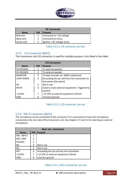
DC Connector<br />
Name PIN Purpose<br />
Red wire 1 Connected to + DC voltage<br />
Black wire 2 Connected to minus<br />
Green wire 3 Ignition + DC voltage sense<br />
Table 3.2.2‐1, DC connector, pin out<br />
3.2.3 I/O connector (RJ45)<br />
The transceiver unit I/O connector is used for multiple purposes described in the table.<br />
I/O Connector<br />
Name PIN Purpose<br />
EX‐SPEAKER 1 To external speaker.<br />
EX‐SPEAKER 2 To external speaker.<br />
MONITOR 3 To tape recorder etc. 600Ω unbalanced<br />
LOW POWER 4 Grounding this pin will force the transmitter to<br />
low power (Gas alarm)<br />
NC 5 Not in use<br />
MUTE 6 Used to mute external equipment. Triggered by<br />
squelch<br />
+12VDC 7 +12 VDC to external equipment (10mA)<br />
GND 8 Common ground<br />
Table 3.2.3‐1, I/O connector, pin out<br />
3.2.4 MIC II connector (RJ45)<br />
The microphone can be connected to this connector if it is convenient to have the microphone<br />
connected at the rear side of the transceiver unit. See chapter 4.7 <strong>and</strong> 5.5 for selecting an external<br />
microphone.<br />
Rear mic. Connector<br />
Name PIN Purpose<br />
MIC. INPUT 1<br />
MIC. GND 2<br />
Headset 3<br />
NC 4 Not in use<br />
NC 5 Not in use<br />
KEY 6 Grounding this pin will key the transmitter<br />
+12VDC 7 +12 VDC to external equipment (10mA)<br />
GND 8 Common ground<br />
Table 3.2.4‐1, MIC II connector, pin out<br />
84417_O&I_<strong>TR</strong>-810_D<br />
2BFunctional description<br />
Page 3‐4


