

Operators and Installation Manual TR-810.pdf - Jotron
Operators and Installation Manual TR-810.pdf - Jotron
Operators and Installation Manual TR-810.pdf - Jotron

You also want an ePaper? Increase the reach of your titles
YUMPU automatically turns print PDFs into web optimized ePapers that Google loves.
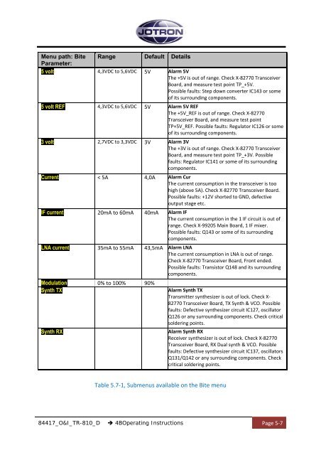
Menu path: Bite Range Default Details<br />
Parameter:<br />
5 volt 4,3VDC to 5,6VDC 5V Alarm 5V<br />
The +5V is out of range. Check X‐82770 Transceiver<br />
Board, <strong>and</strong> measure test point TP_+5V.<br />
Possible faults: Step down converter IC143 or some<br />
of its surrounding components.<br />
5 volt REF 4,3VDC to 5,6VDC 5V Alarm 5V REF<br />
The +5V_REF is out of range. Check X‐82770<br />
Transceiver Board, <strong>and</strong> measure test point<br />
TP+5V_REF. Possible faults: Regulator IC126 or some<br />
of its surrounding components.<br />
3 volt 2,7VDC to 3,3VDC 3V Alarm 3V<br />
The +3V is out of range. Check X‐82770 Transceiver<br />
Board, <strong>and</strong> measure test point TP_+3V. Possible<br />
faults: Regulator IC141 or some of its surrounding<br />
components.<br />
Current < 5A 4,0A Alarm Cur<br />
The current consumption in the transceiver is too<br />
high (above 5A). Check X‐82770 Transceiver Board.<br />
Possible faults: +12V shorted to GND, defective<br />
output stage etc.<br />
IF current 20mA to 60mA 40mA Alarm IF<br />
The current consumption in the 1 IF circuit is out of<br />
range. Check X‐99205 Main Board, 1 IF mixer.<br />
Possible faults: Q143 or some of its surrounding<br />
components.<br />
LNA current 35mA to 55mA 43,5mA Alarm LNA<br />
The current consumption in LNA is out of range.<br />
Check X‐82770 Transceiver Board, Front ended.<br />
Possible faults: Transistor Q148 <strong>and</strong> its surrounding<br />
components.<br />
Modulation 0% to 100% 90%<br />
Synth TX<br />
Synth RX<br />
Alarm Synth TX<br />
Transmitter synthesizer is out of lock. Check X‐<br />
82770 Transceiver Board, TX Synth & VCO. Possible<br />
faults: Defective synthesizer circuit IC127, oscillator<br />
Q126 or any surrounding components. Check critical<br />
soldering points.<br />
Alarm Synth RX<br />
Receiver synthesizer is out of lock. Check X‐82770<br />
Transceiver Board, RX Dual synth & VCO. Possible<br />
faults: Defective synthesizer circuit IC137, oscillators<br />
Q131/Q142 or any surrounding components. Check<br />
critical soldering points.<br />
Table 5.7‐1, Submenus available on the Bite menu<br />
84417_O&I_<strong>TR</strong>-810_D 4BOperating Instructions Page 5‐7


