
Create successful ePaper yourself
Turn your PDF publications into a flip-book with our unique Google optimized e-Paper software.
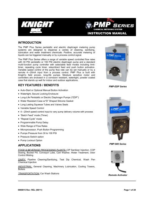
INSTRUCTION MANUAL<br />
INTRODUCTION<br />
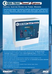
The <strong>PMP</strong> Plus Series peristaltic and electric diaphragm metering pump<br />
systems are designed to dispense a variety of cleaning, sanitizing,<br />
lubrication and water treatment chemicals. Positive, accurate metering of<br />
liquids can be triggered manually or by a process control signal.<br />
The <strong>PMP</strong> Plus Series offers a range of variable speed controlled flow rates<br />
with 30 PSI peristaltic or 100 PSI electric diaphragm pump and a standard<br />
multi-function pump controller with selectable feed modes including limittimer,<br />
repeating cycle timer, relay/direct feed and push button activation.<br />
Variable speed control of the pump flow rate can be set manually or by a<br />
remote 4—20mA input from a process control. <strong>PMP</strong> Plus is built with<br />
Knight’s field proven, long-life pumps. Moisture sensitive motor and<br />
controllers are enclosed in a corrosion resistant, watertight, powder coated<br />
case that stands up well for indoor and outdoor applications.<br />
KEY FEATURES / BENEFITS<br />
Auto-Start or Optional Manual Button Activation<br />
Watertight, Secure Locking Enclosure<br />
Long-Life Peristaltic or Electric Diaphragm Pumps (―EDP‖)<br />
Water Resistant Case w/―D‖ Shaped Silicone Gasket<br />
Long Lasting Squeeze Tubes and Valves Seals<br />
Variable Speed Control<br />
4—20mA speed control input to vary pump delivery volume with process<br />
―Batch Feed‖ mode (Timer)<br />
―Repeat Cycle‖ mode<br />
Programmable Pump Delay<br />
Wide Range of Flow Rates<br />
Microprocessor, Push Button Programming<br />
Pumps Pressure from 30 to 100 PSI<br />
Pressure Switch option<br />
Pump Lockout Option<br />
APPLICATIONS<br />
FOOD & BEVERAGE PROCESSING PLANTS: CIP Sanitizer Injection, COP<br />
Dosing, Bucket Fill, Conveyor Lube, Cart Washer, Water Treatment, Odor<br />
Control Misting<br />
DAIRY: Pipeline Cleaning/Sanitizing, Teat Dip Chemical, Wash Pen<br />
Chemical Injection<br />
INDUSTRIAL: General Cleaning, Machinery Lubrication, Cooling Towers,<br />
Boilers<br />
TRANSPORTATION: Car Wash Stations<br />
<strong>PMP</strong>-EDP Series<br />
<strong>PMP</strong>-900 Series<br />
Remote Activator<br />
0900815 Rev: REL (08/11) Page 1 of 20
CAUTION: Wear protective clothing and eyewear when dispensing chemicals or<br />
other materials. Observe safety handling instructions (MSDS) of chemical mfrs.<br />
CAUTION: To avoid severe or fatal shock, always disconnect main power when<br />
servicing the unit.<br />
CAUTION: When installing any equipment, ensure that all national and local<br />
safety, electrical, and plumbing codes are met.<br />
Page 2 of 20 0900815 Rev: REL (08/11)
RECOMMENDED OPERATING PARAMETERS<br />
Pump Model Duty Cycle Maximum Pump Run<br />
Time<br />
Maximum Lift<br />
(Suction)<br />
Maximum Head<br />
Pressure<br />
<strong>PMP</strong>-800 Models 50% 5 Minutes 10 Feet (3 Meters) 30 PSI (2 Bar)<br />
<strong>PMP</strong>-900 Models 50% 5 Minutes 10 Feet (3 Meters) 30 PSI (2 Bar)<br />
<strong>PMP</strong>-EDP Models 70% 60 Minutes 15 Feet (4.5 Meters) 100 PSI (6.9 Bar)<br />
NOTE: The duty cycles and maximum pump run time specified above can be exceeded, however in doing so the life<br />
of the squeeze tube, roller block and motor may be reduced.<br />
SPECIFICATIONS<br />
Enclosure: Powder coated stainless steel.<br />
Pump Drive: Variable DC.<br />
Squeeze Tube and Valve Seal Materials: Material available for most chemical applications.<br />
Control: Limiting timer, repeating cycle timer, or relay mode.<br />
Dimensions:<br />
<strong>PMP</strong> Plus-800: 9.3‖H x 5.8‖W x 5‖D (23.6cm x 14.7cm x 12.7cm)<br />
<strong>PMP</strong> Plus-900: 13.6‖H x 8‖W x 7.5‖D (34.5cm x 20.3cm x 19.1cm)<br />
<strong>PMP</strong> Plus EDP:13.6‖H x 8‖W x 7.5‖D (34.5cm x 20.3cm x 19.1cm)<br />
Pollution Degree II<br />
Installation category I<br />
Altitude 2000m<br />
Humidity 5 to 95%<br />
Electrical supply 115VAC/60HZ, 230VAC/60HZ, 230VAC/50HZ, 2A<br />
For Indoor Use Only<br />
Temperature 5C to 40C<br />
Mains supply voltage fluctuations are not to exceed 10% of the nominal supply voltage<br />
The unit shall not be positioned so that it is difficult to operate the power disconnecting means<br />
Protection is impaired if the product is used in a manner not specified by the manufacturer<br />
Replacement Fuse for 115V/230V model: 2Amp, 250V, 6.3x32mm, Fast-Acting<br />
PROGRAMMING SETTINGS<br />
Operating<br />
Mode<br />
Signal Input Pump ―ON‖ Time Pump ―OFF‖<br />
Time<br />
Delay On Time On First Off First<br />
KTM 14—240 VAC/VDC 0—12 min 42 sec 0—12 min 42 sec Select Select<br />
CT 14—240 VAC/VDC 0—12 min 42 sec 0—255 min 0—12 min 42 sec Select Select<br />
Relay 14—240 VAC/VDC 1 sec to continuous<br />
4—20 mA External Input (PLC)<br />
0900815 Rev: REL (08/11) Page 3 of 20
THEORY OF OPERATION<br />
The <strong>PMP</strong> Plus chemical metering systems come standard with a unique microcontroller that provides extreme<br />
versatility of use. The multi-function pump controller varies the speed of the pump to provide accurate, precise<br />
injections for almost any chemical batch feed application, repeat cycle injection, pumped misting applications and<br />
direct closed loop injection. The integral circuit board has dual dip switch program/mode selectors that provide the<br />
following operations:<br />
KTM Mode (Timer) Dip Switch#5— This pump ―Limit Timer‖ control is designed to control the run time of the pump<br />
with the press of a button or input of a signal from a powered switch or remote controller. The water proof control<br />
cabinet is normally mounted near the delivery point for the chemical, convenient for operators. Typical delivery points<br />
include Gerry cans, buckets, floor scrubbers, portable foamers or other receptacles. For applications where remote<br />
triggers such as a CIP or Conductivity control signal are used, the controller can be installed close to the signal<br />
source. The signal-input circuit accepts input voltages from 14-240 VAC. The MFSC board also has a ―Relay Mode‖<br />
feature that allows the pump to run from a 14 – 240V signal (for as long as the signal is present) or while the push<br />
button is held down. Using the relay mode with the push button is well suited for manual feed applications.<br />
CT Mode (Repeat Cycle) Dip Switch#5 — This pump ―Cycle Timer‖ triggers a continuous On-Off feed cycle anytime<br />
power is applied to the power input. For continuous chemical applications such as conveyor or track lubrication, the<br />
Repeat Cycle Timer Mode will feed from 0-12 minutes of ON time, with an OFF time from 0-255 minutes off.<br />
INSTALLATION—PERISTALTIC MODELS<br />
(1) Check voltage of installation with a voltmeter and compare with voltage inputs of pump unit before mounting.<br />
Application of incorrect voltage will permanently damage unit and is not covered under warranty.<br />
(2) Mount unit on wall or shelf in a convenient location near both injection point and chemical supply. Do not mount<br />
unit in direct path of steam. This can short circuit and permanently damage your system.<br />
(3) Install power leads. Most systems include a power cord for easy connection. Variable speed systems have an<br />
internal transformer which steps down the incoming voltage. Rigid or flexible conduit should be used to ensure<br />
safety and continued operation without shorts. The green ground wire must be applied to ground. Failure to do<br />
so will void warranty.<br />
(4) Install braided tubing between the discharge (right) tube side of the peristaltic pump and the injection point. Use<br />
the provided stainless steel hose clamps and barb fittings to secure braided tubing to squeeze tube.<br />
(5) Install braided tubing between the suction (left) tube side and the barb fitting on the PVC pickup tube provided.<br />
Use the provided stainless steel hose clamps and barb fittings to secure braided tubing to squeeze tube.<br />
INSTALLATION—ELECTRIC DIAPHRAGM MODELS<br />
(1) Check voltage of installation with a voltmeter and compare with voltage inputs of pump unit before mounting.<br />
Application of incorrect voltage will permanently damage unit and is not covered under warranty.<br />
(2) Mount unit on wall or shelf in a convenient location near both injection point and chemical supply. Do not mount<br />
unit in direct path of steam. This can short circuit and permanently damage your system.<br />
(3) Install power leads. Most systems include a power cord for easy connection. Rigid or flexible conduit should be<br />
used for all 115 and 230 VAC installations to ensure safety and continued operation without shorts. The green<br />
ground wire must be applied to ground. Failure to do so will void warranty.<br />
(4) Install vinyl hose between the discharge (right) tube side of the pump and the injection point. Use hose clamps to<br />
secure tubing to fittings. For all hose routing, avoid any sharp bends which may crimp tubing and restrict flow. As<br />
an alternative, use 90 elbow fittings, but only if absolutely necessary.<br />
(5) Install vinyl hose between the suction (left) tube side and the PVC product pickup tube provided.<br />
PRIMING<br />
(1) Locate the dip-switch pack on the circuit board and set switch #4 to RELAY.<br />
(2) Press and hold the Start button until the chemical line is fully primed, then release the button.<br />
(3) Set switch #4 to TIMER (unless you intend to use relay mode).<br />
Page 4 of 20 0900815 Rev: REL (08/11)
PROGRAMMING KTM (TIMER) MODE<br />
Pump Run Time: (max run time is 12 minutes and 42 seconds)<br />
(1) Locate the dip-switch pack on the lower left portion of the circuit board — set switch #2 to Program, set switch #3<br />
to RUN TIME and set switch #7 to Signal MODE.<br />
(2) Using a measuring cup or beaker, press Start switch and release when pump starts. Let the pump run until<br />
desired amount of chemical is dispensed then press Start switch again to stop. The run time is now programmed.<br />
Repeat step if new volume is required.<br />
(3) Set mode switch #2 to RUN MODE.<br />
Delay Time: (max delay time is 12 minutes and 42 seconds)<br />
(1) Locate the dip-switch pack on the lower left portion of the circuit board — set switch #7 to SIGNAL, set switch #3<br />
to DELAY TIME and set switch #2 to PROGRAM MODE.<br />
(2) Press Start switch and release when the LED begins flashing. When the desired delay time has passed, press<br />
the Start switch again. The delay time is now programmed. Repeat step if new delay time is required.<br />
(3) Set mode switch #2 to RUN MODE.<br />
Lock-Out Time: (max lock-out time is 255 minutes) See Dip Switch located on right side of circuit board.<br />
This feature defeats consecutive dispensing of product for a pre-determined interval. Select a combination of<br />
switches 1 – 8 to program total lock-out time.<br />
Example: For 10 minute lock-out, set switches #2 and #4 to ON with all other switches OFF.<br />
For maximum lock-out (255 min) set all switches ON.<br />
For no lock-out, set all switches OFF.<br />
OPERATION—PUMP FEED MODE SELECT<br />
Manual activation: Press the Start button for 1 full second. The unit will begin counting down the delay time (if used)<br />
and will then run the pump for the amount of time programmed. Once the lock-out time expires (if used) the pump will<br />
be ready to restart.<br />
Signal activation: When the signal input on the circuit board receives a 14-240VAC trigger signal for at least 5<br />
seconds, the delay time (if used) will begin counting down. Then the pump will run for the amount of time<br />
programmed. Once the lock-out time expires (if used) the pump will be ready to restart.<br />
Relay Mode: Set switch #4 to RELAY. The pump will activate for as long as an external trigger signal is present, or<br />
for as long as the manual button is depressed. All other board functions (such as delay time and lock-out time) are by<br />
-passed in relay mode.<br />
DISABLING THE START BUTTON<br />
There is a jumper marked ―JP1‖ on the circuit board that can be used to prevent manual activation in certain<br />
applications, or to allow manual activation by remote push-button only. This jumper only affects the on-board start<br />
button. A remote start button, or trigger signal, can always be used to activate the pump.<br />
When the jumper is ON, the on-board start button is functional.<br />
When the jumper OFF, the on-board start button is disabled.<br />
0900815 Rev: REL (08/11) Page 5 of 20
PROGRAMMING MODES<br />
Dip Switch #2 (Program—Run Mode)<br />
Program mode explained in previous pages.<br />
Run Mode is selected after programming has been completed<br />
Dip Switch #7 (Signal—Power Up)<br />
In the Power Up position allows the pump to be powered by the main power source and run when main power is<br />
applied to the system.<br />
In the Signal position the system requires an input signal from a process control or any voltage signal with an<br />
effective range of 14 –240 VAC<br />
The signal input feature is particularly useful for CIP and other control interface applications.<br />
The signal input circuitry will accept any signal voltage in the range of 14 – 240V. Check the signal voltage with a<br />
meter before connecting to the circuit board. To activate the signal input feature, remove the jumper marked ―JP1‖<br />
from the circuit board.<br />
Dip Switch#6 (On First—Off First)<br />
In the On First position the system will execute the dispense time function for Timer or Repeat Cycle mode when<br />
power is first applied. If a Delay time is programmed the LED will flash until Delay time is elapsed before the pump<br />
starts.<br />
In the Off First position the system will execute the ―off‖ time function for Repeat Cycle mode when power is first<br />
applied.<br />
Dip Switch #1 (Pot-4-20 mA)<br />
Select Pot for potentiometer pump speed control<br />
Select 4-20 mA for installations where automatic process controlled flow rates are required<br />
PROGRAMMING CT (REPEAT CYCLE) MODE<br />
Maximum ON time is 12 minutes and 42 seconds.<br />
Maximum OFF time is 255 minutes.<br />
Locate dip switch #5 and select CT Mode<br />
Setting “OFF” Time<br />
Power should be off when changing this setting. The off time is set by selecting a combination of switches 1 – 8. All<br />
switches that are turned ON will be added up to determine the total off time. For example, if you wish to set a 20<br />
minute off time, set switches #3 and #5 to ON with all other switches OFF.<br />
For maximum off time (255 min) set all switches ON.<br />
The off time resets and begins counting down again the next time the pump runs.<br />
Setting “ON” Time<br />
(1) Ensure that power is on. Be aware that the pump may run briefly — this is normal as the pumps are tested at the<br />
factory during final QC inspection.<br />
(2) Locate the dip-switch pack on the circuit board — set switch #2 to PROGRAM.<br />
(3) Using a measuring cup or beaker, press Start switch and release when pump starts. Let the pump run until<br />
desired amount of chemical is dispensed then press Start switch again to stop. The on time is now programmed.<br />
(4) Set mode switch #2 to RUN MODE.<br />
Page 6 of 20 0900815 Rev: REL (08/11)
SPEED CONTROL<br />
Pump Speed Control is accomplished by manually adjusting pump speed to a desired output speed/concentration<br />
using the circuit board mounted potentiometer or by a dedicated 4-20mA input signal from a PLC. Many CIP process<br />
controls and wash circuit programs are able to output variable signals that regulate the injection of sanitizers and<br />
other process chemicals to achieve targeted PPM concentrations that match fresh water flow rates or desired batch<br />
dose volumes. A simple two wire 4-20mA connection (+/-) (1) from the PLC will run the pump at the rated speed (see<br />
charts on the following pages) and vary the flow rate as the control signal changes in amplitude.<br />
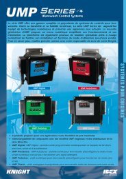
CONNECTING A START SWITCH<br />
A remote, or case mounted, start switch can be connected to the circuit board for manual activation of the pump. See<br />
the diagram below and the wiring diagrams on pages 12—15 that show where the start switch should be connected.<br />
Timer Activation: The start switch will activate the programmed feed time.<br />
Relay Mode: The start switch will run the pump for as long as the switch is depressed.<br />
REMOTE START<br />
SWITCH INPUT<br />
TRIGGER<br />
SIGNAL INPUT<br />
SPEED<br />
CONTROL<br />
SIGNAL<br />
INPUT<br />
CIRCUIT<br />
BOARD<br />
POWER<br />
INPUT<br />
PUMP<br />
OUTPUT<br />
PUMP POWER<br />
INPUT<br />
SPEED CONTROL<br />
POTENTIOMETER<br />
START SWITCH<br />
CONFIGURATION<br />
DIP SWITCHES<br />
DIP SWITCHES<br />
FOR LOCKOUT OR<br />
CYCLE TIME<br />
0900815 Rev: REL (08/11) Page 7 of 20
Pump Speed Data .4 gpm Electric Diaphragm<br />
Current<br />
(ma)<br />
Voltage<br />
(vdc)<br />
Flow (gal/<br />
min)<br />
Flow (oz/<br />
min)<br />
115VAC<br />
Flow (L/<br />
min)<br />
Flow (ml/<br />
min)<br />
Flow (gal/<br />
min)<br />
Flow (oz/<br />
min)<br />
230VAC<br />
Flow (L/<br />
min)<br />
Flow (ml/<br />
min)<br />
3.00 0.72 0.000 0.000 0.000 0 0.000 0.000 0.000 0<br />
3.60 0.864 0.000 0.000 0.000 0 0.000 0.000 0.000 0<br />
4.20 1.008 0.040 5.072 0.150 150 0.048 6.087 0.180 180<br />
4.80 1.152 0.096 12.342 0.365 365 0.116 14.878 0.440 440<br />
5.40 1.296 0.144 18.429 0.545 545 0.177 22.655 0.670 670<br />
6.00 1.44 0.199 25.530 0.755 755 0.248 31.785 0.940 940<br />
6.60 1.584 0.248 31.785 0.940 940 0.301 38.548 1.140 1140<br />
7.20 1.728 0.299 38.210 1.130 1130 0.361 46.156 1.365 1365<br />
7.80 1.872 0.332 42.437 1.255 1255 0.427 54.610 1.615 1615<br />
8.40 2.016 0.367 47.001 1.390 1390 0.489 62.556 1.850 1850<br />
9.00 2.16 0.395 50.552 1.495 1495 0.510 65.261 1.930 1930<br />
9.60 2.304 0.419 53.595 1.585 1585 0.535 68.473 2.025 2025<br />
10.20 2.448 0.446 57.146 1.690 1690 0.567 72.531 2.145 2145<br />
10.80 2.592 0.466 59.682 1.765 1765 0.590 75.574 2.235 2235<br />
11.40 2.736 0.483 61.880 1.830 1830 0.612 78.279 2.315 2315<br />
12.00 2.88 0.499 63.909 1.890 1890 0.630 80.646 2.385 2385<br />
12.60 3.024 0.515 65.937 1.950 1950 0.650 83.182 2.460 2460<br />
13.20 3.168 0.524 67.121 1.985 1985 0.663 84.873 2.510 2510<br />
13.80 3.312 0.535 68.473 2.025 2025 0.680 87.071 2.575 2575<br />
14.40 3.456 0.544 69.657 2.060 2060 0.692 88.593 2.620 2620<br />
15.00 3.6 0.556 71.179 2.105 2105 0.703 89.945 2.660 2660<br />
15.60 3.744 0.567 72.531 2.145 2145 0.712 91.129 2.695 2695<br />
16.20 3.888 0.575 73.545 2.175 2175 0.716 91.636 2.710 2710<br />
16.80 4.032 0.581 74.391 2.200 2200 0.724 92.650 2.740 2740<br />
17.40 4.176 0.590 75.574 2.235 2235 0.733 93.834 2.775 2775<br />
18.00 4.32 0.594 76.082 2.250 2250 0.738 94.510 2.795 2795<br />
18.60 4.464 0.602 77.096 2.280 2280 0.741 94.848 2.805 2805<br />
19.20 4.608 0.606 77.603 2.295 2295 0.745 95.356 2.820 2820<br />
19.80 4.752 0.613 78.449 2.320 2320 0.793 101.442 3.000 3000<br />
20.40 4.896 0.617 78.956 2.335 2335 0.794 101.611 3.005 3005<br />
Page 8 of 20 0900815 Rev: REL (08/11)
Pump Speed Data 1.5 gpm Electric Diaphragm<br />
Current<br />
(ma)<br />
Voltage<br />
(vdc)<br />
Flow (gal/<br />
min)<br />
Flow (oz/<br />
min)<br />
115VAC<br />
Flow (L/<br />
min)<br />
Flow (ml/<br />
min)<br />
Flow (gal/<br />
min)<br />
Flow (oz/<br />
min)<br />
230VAC<br />
Flow (L/<br />
min)<br />
Flow (ml/<br />
min)<br />
3.00 0.72 0.000 0.000 0.000 0 0.000 0.000 0.000 0<br />
3.60 0.864 0.000 0.000 0.000 0 0.000 0.000 0.000 0<br />
4.20 1.008 0.026 3.381 0.100 100 0.055 7.101 0.210 210<br />
4.80 1.152 0.133 17.076 0.505 505 0.161 20.627 0.610 610<br />
5.40 1.296 0.221 28.235 0.835 835 0.246 31.447 0.930 930<br />
6.00 1.44 0.339 43.451 1.285 1285 0.384 49.199 1.455 1455<br />
6.60 1.584 0.428 54.779 1.620 1620 0.476 60.865 1.800 1800<br />
7.20 1.728 0.516 66.106 1.955 1955 0.568 72.700 2.150 2150<br />
7.80 1.872 0.584 74.729 2.210 2210 0.635 81.323 2.405 2405<br />
8.40 2.016 0.650 83.182 2.460 2460 0.705 90.283 2.670 2670<br />
9.00 2.16 0.715 91.467 2.705 2705 0.763 97.723 2.890 2890<br />
9.60 2.304 0.758 97.046 2.870 2870 0.810 103.640 3.065 3065<br />
10.20 2.448 0.806 103.133 3.050 3050 0.861 110.234 3.260 3260<br />
10.80 2.592 0.841 107.698 3.185 3185 0.902 115.475 3.415 3415<br />
11.40 2.736 0.880 112.601 3.330 3330 0.939 120.209 3.555 3555<br />
12.00 2.88 0.913 116.827 3.455 3455 0.975 124.774 3.690 3690<br />
12.60 3.024 0.943 120.716 3.570 3570 1.009 129.170 3.820 3820<br />
13.20 3.168 0.968 123.928 3.665 3665 1.036 132.551 3.920 3920<br />
13.80 3.312 0.992 126.972 3.755 3755 1.065 136.271 4.030 4030<br />
14.40 3.456 1.001 128.155 3.790 3790 1.082 138.468 4.095 4095<br />
15.00 3.6 1.033 132.213 3.910 3910 1.104 141.343 4.180 4180<br />
15.60 3.744 1.066 136.440 4.035 4035 1.125 144.048 4.260 4260<br />
16.20 3.888 1.071 137.116 4.055 4055 1.150 147.260 4.355 4355<br />
16.80 4.032 1.090 139.483 4.125 4125 1.164 148.951 4.405 4405<br />
17.40 4.176 1.104 141.343 4.180 4180 1.181 151.149 4.470 4470<br />
18.00 4.32 1.120 143.371 4.240 4240 1.198 153.347 4.535 4535<br />
18.60 4.464 1.127 144.217 4.265 4265 1.210 154.868 4.580 4580<br />
19.20 4.608 1.147 146.753 4.340 4340 1.224 156.728 4.635 4635<br />
19.80 4.752 1.157 148.105 4.380 4380 1.232 157.742 4.665 4665<br />
20.40 4.896 1.172 149.965 4.435 4435 1.259 161.124 4.765 4765<br />
0900815 Rev: REL (08/11) Page 9 of 20
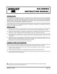
Pump Speed Data 3.2 gpm Electric Diaphragm<br />
Current<br />
(ma)<br />
Voltage<br />
(vdc)<br />
Flow (gal/<br />
min)<br />
Flow (oz/<br />
min)<br />
115VAC<br />
Flow (L/<br />
min)<br />
Flow (ml/<br />
min)<br />
Flow (gal/<br />
min)<br />
Flow (oz/<br />
min)<br />
230VAC<br />
Flow (L/<br />
min)<br />
Flow (ml/<br />
min)<br />
3.00 0.72 0.000 0.000 0.000 0 0.000 0.000 0.000 0<br />
3.60 0.864 0.000 0.000 0.000 0 0.000 0.000 0.000 0<br />
4.20 1.008 0.099 12.680 0.375 375 0.147 18.767 0.555 555<br />
4.80 1.152 0.345 44.127 1.305 1305 0.371 47.509 1.405 1405<br />
5.40 1.296 0.543 69.488 2.055 2055 0.561 71.855 2.125 2125<br />
6.00 1.44 0.884 113.108 3.345 3345 0.902 115.475 3.415 3415<br />
6.60 1.584 1.136 145.400 4.300 4300 1.131 144.724 4.280 4280<br />
7.20 1.728 1.346 172.282 5.095 5095 1.335 170.930 5.055 5055<br />
7.80 1.872 1.506 192.740 5.700 5700 1.510 193.247 5.715 5715<br />
8.40 2.016 1.647 210.830 6.235 6235 1.672 214.043 6.330 6330<br />
9.00 2.16 1.787 228.752 6.765 6765 1.818 232.640 6.880 6880<br />
9.60 2.304 1.889 241.770 7.150 7150 1.944 248.871 7.360 7360<br />
10.20 2.448 1.997 255.634 7.560 7560 2.074 265.440 7.850 7850<br />
10.80 2.592 2.082 266.454 7.880 7880 2.170 277.782 8.215 8215<br />
11.40 2.736 2.158 276.261 8.170 8170 2.243 287.081 8.490 8490<br />
12.00 2.88 2.236 286.236 8.465 8465 2.345 300.099 8.875 8875<br />
12.60 3.024 2.301 294.520 8.710 8710 2.425 310.413 9.180 9180<br />
13.20 3.168 2.347 300.438 8.885 8885 2.485 318.021 9.405 9405<br />
13.80 3.312 2.412 308.722 9.130 9130 2.562 327.996 9.700 9700<br />
14.40 3.456 2.448 313.287 9.265 9265 2.609 333.913 9.875 9875<br />
15.00 3.6 2.494 319.204 9.440 9440 2.671 341.860 10.110 10110<br />
15.60 3.744 2.540 325.122 9.615 9615 2.729 349.299 10.330 10330<br />
16.20 3.888 2.586 331.039 9.790 9790 2.787 356.738 10.550 10550<br />
16.80 4.032 2.615 334.759 9.900 9900 2.829 362.148 10.710 10710<br />
17.40 4.176 2.658 340.169 10.060 10060 2.872 367.558 10.870 10870<br />
18.00 4.32 2.692 344.565 10.190 10190 2.919 373.645 11.050 11050<br />
18.60 4.464 2.724 348.623 10.310 10310 2.956 378.379 11.190 11190<br />
19.20 4.608 2.753 352.342 10.420 10420 2.994 383.282 11.335 11335<br />
19.80 4.752 2.782 356.062 10.530 10530 3.027 387.509 11.460 11460<br />
20.40 4.896 2.813 360.119 10.650 10650 3.068 392.750 11.615 11615<br />
Page 10 of 20 0900815 Rev: REL (08/11)
Pump Speed Data Peristaltic<br />
Current<br />
(ma)<br />
Voltage<br />
(vdc)<br />
Flow (gal/<br />
min)<br />
Flow (oz/<br />
min)<br />
9110V<br />
Flow (L/<br />
min)<br />
Flow (ml/<br />
min)<br />
Flow (gal/<br />
min)<br />
Flow (oz/<br />
min)<br />
8110V<br />
Flow (L/<br />
min)<br />
Flow (ml/<br />
min)<br />
3.00 0.72 0.000 0.000 0.000 0.00 0.000 0.000 0.000 0<br />
3.60 0.864 0.000 0.000 0.000 0.00 0.000 0.000 0.000 0<br />
4.20 1.008 0.016 2.029 0.060 60.00 0.000 0.000 0.000 0<br />
4.80 1.152 0.053 6.763 0.200 200.00 0.007 0.845 0.025 25<br />
5.40 1.296 0.100 12.849 0.380 380.00 0.013 1.691 0.050 50<br />
6.00 1.44 0.148 18.936 0.560 560.00 0.018 2.367 0.070 70<br />
6.60 1.584 0.195 25.022 0.740 740.00 0.034 4.396 0.130 130<br />
7.20 1.728 0.240 30.771 0.910 910.00 0.063 8.115 0.240 240<br />
7.80 1.872 0.272 34.828 1.030 1030.00 0.090 11.497 0.340 340<br />
8.40 2.016 0.312 39.901 1.180 1180.00 0.123 15.724 0.465 465<br />
9.00 2.16 0.341 43.620 1.290 1290.00 0.155 19.781 0.585 585<br />
9.60 2.304 0.370 47.340 1.400 1400.00 0.168 21.472 0.635 635<br />
10.20 2.448 0.400 51.228 1.515 1515.00 0.184 23.501 0.695 695<br />
10.80 2.592 0.428 54.779 1.620 1620.00 0.192 24.515 0.725 725<br />
11.40 2.736 0.450 57.653 1.705 1705.00 0.199 25.530 0.755 755<br />
12.00 2.88 0.465 59.513 1.760 1760.00 0.207 26.544 0.785 785<br />
12.60 3.024 0.497 63.570 1.880 1880.00 0.215 27.558 0.815 815<br />
13.20 3.168 0.509 65.092 1.925 1925.00 0.217 27.727 0.820 820<br />
13.80 3.312 0.532 68.135 2.015 2015.00 0.221 28.235 0.835 835<br />
14.40 3.456 0.539 68.981 2.040 2040.00 0.227 29.080 0.860 860<br />
15.00 3.6 0.560 71.686 2.120 2120.00 0.230 29.418 0.870 870<br />
15.60 3.744 0.560 71.686 2.120 2120.00 0.234 29.925 0.885 885<br />
16.20 3.888 0.569 72.869 2.155 2155.00 0.239 30.602 0.905 905<br />
16.80 4.032 0.582 74.560 2.205 2205.00 0.240 30.771 0.910 910<br />
17.40 4.176 0.588 75.236 2.225 2225.00 0.243 31.109 0.920 920<br />
18.00 4.32 0.592 75.743 2.240 2240.00 0.246 31.447 0.930 930<br />
18.60 4.464 0.600 76.758 2.270 2270.00 0.248 31.785 0.940 940<br />
19.20 4.608 0.609 77.941 2.305 2305.00 0.248 31.785 0.940 940<br />
19.80 4.752 0.613 78.449 2.320 2320.00 0.250 31.954 0.945 945<br />
20.40 4.896 0.625 79.970 2.365 2365.00 0.252 32.292 0.955 955<br />
0900815 Rev: REL (08/11) Page 11 of 20
WIRING DIAGRAM—PERISTALTIC (115 VAC)<br />
Page 12 of 20 0900815 Rev: REL (08/11)
WIRING DIAGRAM—PERISTALTIC (230 VAC)<br />
0900815 Rev: REL (08/11) Page 13 of 20
WIRING DIAGRAM—ELECTRIC DIAPHRAGM (115 VAC)<br />
Page 14 of 20 0900815 Rev: REL (08/11)
WIRING DIAGRAM—ELECTRIC DIAPHRAGM (230 VAC)<br />
0900815 Rev: REL (08/11) Page 15 of 20
SPARE PARTS—PERISTALTIC MODELS<br />
Part Number<br />
Description<br />
7010116 800 Series Motor<br />
7631331 800 Series Pump Body<br />
7633330 800 Series Roller Block<br />
7018068 800 Series EPDM Squeeze Tube (T-66-E)<br />
7018087 800 Series Viton Squeeze Tube (T-66-F)<br />
7630330 800 Series Face Plate<br />
7010237 900 Series Motor<br />
7630701 900 Series Pump Body<br />
7630731-1 900 Series Roller Block<br />
7028662 900 Series Squeeze Tube (T-86-E)<br />
7630712 900 Series Face Plate<br />
SPARE PARTS—ELECTRIC DIAPHRAGM MODELS<br />
Part Number<br />
Description<br />
7317323 Three Chamber Upper Housing Assembly<br />
7317324 Three Chamber Lower Housing Assembly<br />
7317321 Three Chamber Valve Housing Assembly EPDM<br />
7317322 Three Chamber Valve Housing Assembly Viton<br />
7317317 Five Chamber Upper Housing Assembly<br />
7317320 Five Chamber Lower Housing Assembly<br />
7317326 Five Chamber Valve Housing Assembly EPDM<br />
7317325 Five Chamber Valve Housing Assembly Viton<br />
1600139-01 Motor/Pump for <strong>PMP</strong>E-550V3.2, EPDM 115 VAC<br />
1600139-02 Motor/Pump for <strong>PMP</strong>E-550V3.2, EPDM 230 VAC<br />
1600137-01 Motor/Pump for <strong>PMP</strong>E-770V1.5, EPDM 115 VAC<br />
1600137-02 Motor/Pump for <strong>PMP</strong>E-770V1.5, EPDM 230 VAC<br />
1600144-01 Motor/Pump for <strong>PMP</strong>E-550V3.2, Viton 115 VAC<br />
1600144-02 Motor/Pump for <strong>PMP</strong>E-550V3.2, Viton 230 VAC<br />
1600135-01 Motor/Pump for <strong>PMP</strong>E-770V.4, EPDM 115 VAC<br />
1600136-01 Motor/Pump for <strong>PMP</strong>E-770V.4, Viton 115 VAC<br />
1600138-01 Motor/Pump for <strong>PMP</strong>E-770V1.5, Viton 115 VAC<br />
1600138-02 Motor/Pump for <strong>PMP</strong>E-770V1.5, Viton 230 VAC<br />
1600131-01 Motor/Pump for <strong>PMP</strong>E-770V1.5PS, EPDM 115 VAC<br />
1600132-01 Motor/Pump for <strong>PMP</strong>E-770V1.5PS, Viton 115 VAC<br />
1600800 Fitting, EPDM, Straight, 1/2"<br />
1600801 Fitting, Viton, Straight, 1/2"<br />
1600802 Fitting, EPDM, ELL, 1/2"<br />
1600803 Fitting, Viton, ELL, 1/2"<br />
1600804 Fitting, EPDM, Straight, 3/8"<br />
1600805 Fitting, Viton, Straight, 3/8"<br />
1600806 Fitting, EPDM, ELL, 3/8"<br />
1600807 Fitting, Viton, ELL, 3/8"<br />
Page 16 of 20 0900815 Rev: REL (08/11)
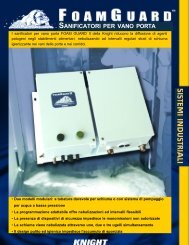
EXPLODED PARTS NOMENCLATURE DIAGRAMS<br />
5 CHAMBER VALVE<br />
HOUSING ASSY<br />
5 CHAMBER LOWER<br />
HOUSING ASSY<br />
5 CHAMBER UPPER<br />
HOUSING ASSY<br />
3 CHAMBER VALVE<br />
HOUSING ASSY<br />
3 CHAMBER UPPER<br />
HOUSING ASSY<br />
3 CHAMBER LOWER<br />
HOUSING ASSY<br />
0900815 Rev: REL (08/11) Page 17 of 20
TROUBLESHOOTING—PERISTALTIC MODELS<br />
Pump will not hold prime:<br />
Check for air leaks in the suction line up to the pump.<br />
Check for excessive roller block wear.<br />
Pump does not trigger from signal:<br />
Check signal voltage and duration.<br />
Check pump run and delay time settings.<br />
Pump may be counting down a "lockout" time (if used) from a previous activation.<br />
Pump will not turn when trying to prime, or normal activation:<br />
Check for loose pump motor wires.<br />
Check for voltage from circuit board to motor.<br />
Check for mechanical binding of moving parts.<br />
Pump turns but do not dispense product:<br />
Check product containers.<br />
Check squeeze tube for wear.<br />
Check condition of roller and pump housing.<br />
Check for air leaks on suction line.<br />
Check for blockage from pump tube into injection point.<br />
Pump triggers at incorrect time:<br />
Check supply signal input for repeat signals from control source.<br />
Check signal lock-out function.<br />
MAINTENANCE—PERISTALTIC MODELS<br />
Peristaltic pumps require a minimal amount of maintenance to achieve optimal performance. Periodically check the<br />
squeeze tube for cracks, deterioration, or swelling. The squeeze tube will typically need to be replaced about every 6<br />
months (chemical compatibility and duty cycle can cause this interval to vary).<br />
Applying lube to the squeeze tube once a month will extend the life of the tube, minimize wear on other contacting<br />
parts, and promote smoother pump operation. Use Knight Tube Lube (P/N 7506621) or an equivalent silicone-based<br />
lubricant.<br />
(1) Remove the faceplate of the pump.<br />
(2) Apply a thin bead of Tube Lube to the inner surface (the side that the rollers contact) of the squeeze tube<br />
between the 9 o’clock and 3 o’clock positions. Avoid getting lube near the pinch points where the bottom of the<br />
faceplate grips the tube.<br />
(3) Put the faceplate back on the pump.<br />
(4) Activate the pump under normal operation — the lubricant will be evenly distributed as the pump rotates.<br />
Page 18 of 20 0900815 Rev: REL (08/11)
TROUBLESHOOTING—ELECTRIC DIAPHRAGM MODELS<br />
Pump does not run:<br />
Blown fuse inside the <strong>PMP</strong> unit.<br />
Tripped breaker at the power source that the <strong>PMP</strong> is connected to.<br />
Incorrect polarity on pump motor wiring to circuit board.<br />
Pump will not prime/difficult to prime:<br />
Check for air leaks at the inlet fitting on the pump.<br />
Check for obstruction in the chemical suction line and also discharge line (Pump will prime only if all pressure is<br />
relieved from outlet port).<br />
Possible debris stuck in the diaphragms or damage to the diaphragms.<br />
If the pump fails to prime, pour a small amount of water into the suction port while the pump is running, then reconnect<br />
the suction hose. Once the pump is primed with water the valves/diaphragm are ready for chemical.<br />
Low flow or low output pressure:<br />
Loose or broken inlet fitting on suction side of pump (causes air in the pump or in the tubing).<br />
Incorrect speed adjustment setting on circuit board.<br />
Pump motor damaged or diaphragm seals damaged.<br />
Pump leaks:<br />
Diaphragm possibly damaged.<br />
Inlet and/or outlet fittings possibly cracked.<br />
MAINTENANCE—ELECTRIC DIAPHRAGM MODELS<br />
Flushing the pump with warm water every 60—90 days will prolong the life of your pump.<br />
Fluctuations in power will change pump speed. Be sure your power source provides proper voltage.<br />
DISCLAIMER<br />
Knight LLC does not accept responsibility for the mishandling, misuse, or non-performance of the described items<br />
when used for purposes other than those specified in the instructions. For hazardous materials information consult<br />
label, MSDS, or Knight LLC. Knight products are not for use in potentially explosive environments. Any use of our<br />
equipment in such an environment is at the risk of the user, Knight does not accept any liability in such<br />
circumstances.<br />
WARRANTY<br />
All Knight controls and pump systems are warranted against defects in material and workmanship for a period of<br />
ONE year. All electronic control boards have a TWO year warranty. Warranty applies only to the replacement or<br />
repair of such parts when returned to factory with a Knight Return Authorization (KRA) number, freight prepaid, and<br />
found to be defective upon factory authorized inspection. Bearings and pump seals or rubber and synthetic rubber<br />
parts such as ―O‖ rings, diaphragms, squeeze tubing, and gaskets are considered expendable and are not covered<br />
under warranty. Warranty does not cover liability resulting from performance of this equipment nor the labor to<br />
replace this equipment. Product abuse or misuse voids warranty.<br />
FOOTNOTE<br />
The information and specifications included in this publication were in effect at the time of approval for printing. Knight<br />
LLC reserves the right, however, to discontinue or change specifications or design at any time without notice and<br />
without incurring any obligation whatsoever.<br />
0900815 Rev: REL (08/11) Page 19 of 20
Knight Headquarters<br />
Tel: 949.595.4800<br />
Fax: 949.595.4801<br />
USA Toll Free<br />
Tel: 800.854.3764<br />
Fax: 800.752.9518<br />
KNIGHT LLC, A Unit of IDEX Corporation (www.knightequip.com)<br />
Knight Canada<br />
Tel: 905.542.2333<br />
Fax: 905.542.1536<br />
Knight Europe<br />
Tel: 44.1293.615.570<br />
Fax: 44.1293.615.585<br />
Knight Australia<br />
Tel: 61.2.9725.2588<br />
Fax: 61.2.9725.2025<br />
Knight N. Asia<br />
Tel: 82.2.3481.6683<br />
Fax: 82.2.3482.5742<br />
Knight S. Asia<br />
Tel: 65.6763.6633<br />
Fax: 65.6764.4020<br />
Page 20 of 20 0900815 Rev: REL (08/11)