Line components Contents Page - Erawan Refrigeration Co., Ltd.
Line components Contents Page - Erawan Refrigeration Co., Ltd.
Line components Contents Page - Erawan Refrigeration Co., Ltd.

Create successful ePaper yourself
Turn your PDF publications into a flip-book with our unique Google optimized e-Paper software.
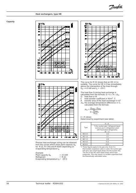
Heat exchangers, type HE<br />
Capacity<br />
The curve for R 22 shows that an HE 4.0 is<br />
suitable. The curve for HE 4.0 lies immediately<br />
above the intersection of the lines through<br />
Q e = 4.5 kW and t e = −25C.<br />
The heat flow Q during heat exchange is<br />
calculated from the formula: Q = k × A × ∆t m<br />
Q heat flow in W<br />
k heat transfer coefficient in W/m 2 C<br />
A transfer area of the heat exchanger in m 2<br />
∆t m the average temperature difference in C,<br />
calculated from the formula:<br />
∆t max. −∆t<br />
∆t min.<br />
m =<br />
∆t<br />
ln max.<br />
∆tmin.<br />
k × A values<br />
Determined by experiment (see table).<br />
Precise heat exchanger sizing can be obtained<br />
from the curves which show plant capacity Q e<br />
for R 22, R 134a and R 404A depending on<br />
evaporating temperature t e .<br />
Example<br />
Plant capacity Q e = 4.5 kW<br />
Refrigerant = R 22<br />
Evaporating temperature t e = −25°C<br />
K × A<br />
1 ) Dry suction gas / refrigerant liquid<br />
Type (normal use in refrigeration plant<br />
with fluorinated refrigerants)<br />
W / C<br />
HE 0.5 2.3<br />
HE 1.0 3.1<br />
HE 1.5 4.9<br />
HE 4.0 11.0<br />
HE 8.0 23.0<br />
1 ) These figures apply to dry gas only. Even if a<br />
thermostatic expansion valve is used, the suction gas<br />
will carry very small liquid drops into the suction line.<br />
The fins of the HE catch these drops which then<br />
evaporate. This may result in a smaller superheat than<br />
the theoretically calculated value.<br />
58 Technical leaflet - RD6KA302 © Danfoss A/S (RC-CM / MWA), 03 - 2002