Quadrifoglio Manual - Ferroli
Quadrifoglio Manual - Ferroli
Quadrifoglio Manual - Ferroli

You also want an ePaper? Increase the reach of your titles
YUMPU automatically turns print PDFs into web optimized ePapers that Google loves.
QUADRIFOGLIO<br />
|||||||||||||<br />
|||||||||||||<br />
EN<br />
1. GENERAL INSTRUCTIONS<br />
• Carefully read the instructions contained in this instruction booklet.<br />
• After boiler installation, inform the user regarding its operation and give him this<br />
manual, which is an integral and essential part of the product and must be kept with<br />
care for future reference.<br />
• Installation and maintenance must be carried out by professionally qualified personnel,<br />
according to current regulations and the manufacturer's instructions. Do not carry<br />
out any operation on the sealed control parts.<br />
• Incorrect installation or inadequate maintenance can result in damage or injury. The<br />
Manufacturer declines any liability for damage due to errors in installation and use<br />
or failure to follow the instructions.<br />
• Before carrying out any cleaning or maintenance operation, disconnect the unit from<br />
the power supply using the system switch and/or the special cut-off devices.<br />
• In case of a fault and/or poor operation, deactivate the unit and do not attempt to<br />
repair it or directly intervene. Contact professionally qualified personnel. Repair/replacement<br />
of the products must only be carried out by professionally qualified using<br />
original spare parts. Failure to comply with the above could affect the safety of the<br />
unit.<br />
• This unit must only be used for its intended purpose. Any other use is considered<br />
improper and therefore dangerous.<br />
• The packing materials are potentially hazardous and must not be left within the<br />
reach of children.<br />
• The unit must not be used by people (including children) with limited physical, sensory<br />
or mental abilities or without experience and knowledge of it, unless instructed<br />
or supervised in its use by someone responsible for their safety.<br />
• The images given in this manual are a simplified representation of the product. In<br />
this representation there may be slight and insignificant differences with respect to<br />
the product supplied.<br />
2. OPERATING INSTRUCTIONS<br />
2.1 Introduction<br />
Dear Customer<br />
Thank you for choosing QUADRIFOGLIO, a boiler with base FERROLI featuring advanced<br />
design, cutting-edge technology, high reliability and quality construction. Please<br />
read this manual carefully since it provides important information on safe installation, use<br />
and maintenance.<br />
QUADRIFOGLIO is a high efficiency, low emissions premix condensing heat generator<br />
for heating, running on natural gas or LPG and equipped with a microprocessor control<br />
system.<br />
The boiler shell consists of a patented stainless steel helical tube exchanger and a<br />
premix burner in steel, equipped with electronic ignition and ionization flame control, a<br />
modulating speed fan and a modulating gas valve. QUADRIFOGLIO is a heat generator<br />
arranged to operate alone or in cascade.<br />
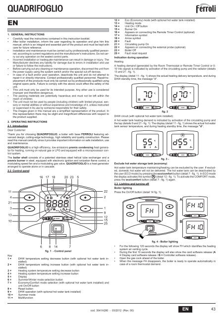
2.2 Control panel<br />
11<br />
4<br />
21<br />
3<br />
13<br />
10<br />
16<br />
17 18 20 23<br />
reset<br />
eco<br />
comfort<br />
5<br />
22<br />
2<br />
1<br />
9<br />
12<br />
15<br />
25<br />
12 = Eco (Economy) mode (with optional hot water tank installed)<br />
13 = Heating mode<br />
14 = Unit On / Off button<br />
15 = Burner On<br />
16 = Appears on connecting the Remote Timer Control (optional)<br />
17 = Information symbol<br />
18 = Arrow symbol<br />
20 = Fault<br />
21 = Circulating pump On<br />
22 = Appears on connecting the external probe (optional)<br />
23 = Boiler Off<br />
25 = Fault reset request<br />
Indication during operation<br />
Heating<br />
A heating demand (generated by the Room Thermostat or Remote Timer Control or 0-<br />
10 Vdc signal) is indicated by activation of the circulating pump and the radiator (details<br />
13 and 21 - fig. 1).<br />
The display (detail 11 - fig. 1) shows the actual heating delivery temperature, and during<br />
DHW standby time, the message "d".<br />
fig. 2<br />
DHW circuit (with optional hot water tank installed)<br />
A hot water tank heating demand is indicated by activation of the circulating pump and<br />
the tap (details 9 and 21 - fig. 1). The display (detail 11 - fig. 1) shows the actual hot water<br />
tank sensor temperature, and during heating standby time, the message "d“.<br />
fig. 3 -<br />
Exclude hot water storage tank (economy)<br />
Hot water tank temperature maintaining/heating can be excluded by the user. If excluded,<br />
domestic hot water will not be delivered. The hot water tank can be deactivated by<br />
the user (ECO mode) by pressing the eco/comfort button (detail 7 - fig. 1). In ECO mode<br />
the display activates the symbol (detail 12 - fig. 1). To activate the COMFORT mode,<br />
press the eco/comfort button (detail 7 - fig. 1) again.<br />
2.3 Lighting and turning off<br />
Boiler lighting<br />
reset<br />
reset<br />
Press the On/Off button (detail 14 fig. 1).<br />
reset<br />
eco<br />
comfort<br />
eco<br />
comfort<br />
eco<br />
comfort<br />
||||||||||<br />
reset<br />
reset<br />
A<br />
||||||||||<br />
B<br />
eco<br />
comfort<br />
eco<br />
comfort<br />
reset<br />
eco<br />
comfort<br />
reset<br />
eco<br />
comfort<br />
6 8 14<br />
fig. 1 - Control panel<br />
Key<br />
1 = DHW temperature setting decrease button (with optional hot water tank installed)<br />
2 = DHW temperature setting increase button (with optional hot water tank installed)<br />
3 = Heating system temperature setting decrease button<br />
4 = Heating system temperature setting increase button<br />
5 = Display<br />
6 = Summer/Winter mode selection button<br />
7 = Economy/Comfort mode selection (with optional hot water tank installed) and<br />
unit On/Off button<br />
8 = Reset button<br />
9 = DHW operation (with optional hot water tank installed)<br />
10 = Summer mode<br />
11 = Multifunction<br />
7<br />
fig. 4 - Boiler lighting<br />
• For the following 120 seconds the display will show FH which identifies the heating<br />
system air venting cycle.<br />
• During the first 10 seconds the display will also show the card software release (A<br />
= Display card software release / B = Controller software release).<br />
• Open the gas cock ahead of the boiler.<br />
• When the message FH disappears, the boiler is ready to operate automatically in<br />
case of a room thermostat demand.<br />
cod. 3541A280 - 03/2012 (Rev. 00)<br />
EN<br />
43
QUADRIFOGLIO<br />
Turning the boiler off<br />
Press the button<br />
(detail 7 - fig. 1) for 5 seconds.<br />
fig. 5 - Turning the boiler off<br />
When the boiler is turned off, the PCB is still powered.<br />
Domestic hot water (with optional hot water tank installed) and heating operation are disabled.<br />
The antifreeze system remains activated.<br />
To relight the boiler, press the button<br />
fig. 6<br />
(detail 7 fig. 1) again for 5 seconds.<br />
The boiler will be immediately ready to operate whenever domestic hot water is drawn<br />
(with optional hot water tank installed) or in case of a room thermostat demand.<br />
To completely disconnect the power to the unit, press the button detail 14 fig. 1.<br />
B<br />
The antifreeze system does not work when the power and/or gas to the unit are<br />
turned off. To avoid damage caused by freezing during long idle periods in winter,<br />
it is advisable to drain all water from the boiler, DHW circuit and system; or<br />
drain just the DHW circuit and add a suitable antifreeze to the heating system,<br />
complying with that prescribed in sec. 3.3.<br />
2.4 Adjustments<br />
Summer/Winter Switchover<br />
Press the button<br />
reset<br />
reset<br />
eco<br />
comfort<br />
eco<br />
comfort<br />
detail 6 - fig. 1 for 1 second.<br />
Room temperature adjustment (with optional room thermostat)<br />
Using the room thermostat, set the temperature required in the rooms.<br />
Room temperature adjustment (with optional remote timer control)<br />
Using the remote timer control, set the temperature desired in the rooms. The boiler unit<br />
will set the system water according to the required room temperature. For information on<br />
the remote timer control, please refer to its user's manual.<br />
Sliding temperature<br />
When the optional external probe is installed the corresponding symbol (detail 22 fig. 1)<br />
is activated on the control panel display (detail 5 - fig. 1). The boiler control system works<br />
with "Sliding Temperature". In this mode, the heating system temperature is controlled<br />
according to the outside weather conditions in order to ensure high comfort and energy<br />
saving throughout the year. In particular, as the outside temperature increases, the system<br />
delivery temperature is decreased according to a specific "compensation curve".<br />
With Sliding Temperature adjustment, the temperature set with the heating buttons<br />
(details3 and 4 - fig. 1) becomes the maximum system delivery temperature. It is advisable<br />
to set a maximum value to allow system adjustment throughout its useful operating<br />
range.<br />
The boiler must be adjusted at the time of installation by qualified personnel. Adjustments<br />
can in any case be made by the user to improve comfort .<br />
Compensation curve and curve offset<br />
Press the reset buttonfig. 1 (detail 8 - ) for 5 seconds, to display the actual compensation<br />
curve (fig. 10) which can be modified with the DHW buttons (details 1 and 2 - fig. 1).<br />
Adjust the required curve from 1 to 10 according to the characteristic (fig. 12).<br />
By setting the curve to 0, sliding temperature adjustment is disabled.<br />
IIIIIIIIIIIIIIII<br />
IIIIIIIIIIIIIII<br />
reset<br />
fig. 10 - Compensation curve<br />
Press the heating buttons (details 3 and 4 - fig. 1) to access parallel curve offset<br />
(fig. 13), modifiable with the DHW buttons (details 1 and 2 - fig. 1).<br />
eco<br />
comfort<br />
IIIIIIIIIIIIIIIII<br />
IIIIIIIIIIIIIIIII<br />
fig. 7<br />
The display activates the Summer symbol detail 10 - fig. 1. The heating function is deactivated,<br />
whereas the possible production of domestic hot water (with optional external hot<br />
water tank) remains activated. The antifreeze system remains activated.<br />
(detail 6 - fig. 1) again for 1 sec-<br />
To deactivate Summer mode, press the button<br />
ond.<br />
Heating temperature adjustment<br />
Use the heating buttons<br />
(details 3 and 4 - fig. 1) to adjust the temperature<br />
from a min. of 20°C to a max. of 90°C.<br />
reset<br />
eco<br />
comfort<br />
reset<br />
fig. 11 - Curve parallel offset<br />
Press the reset button (detail 8 - fig. 1) again for 5 seconds to exit parallel curve adjustment<br />
mode.<br />
If the room temperature is lower than the required value, it is advisable to set a higher<br />
order curve and vice versa. Proceed by increasing or decreasing in steps of one and<br />
check the result in the room.<br />
90<br />
85<br />
80<br />
70<br />
eco<br />
comfort<br />
10 9 8 7<br />
6<br />
5<br />
4<br />
60<br />
3<br />
IIIIIIIIIIIIIIIIIII<br />
IIIIIIIIIIIIIII<br />
50<br />
40<br />
2<br />
1<br />
30<br />
fig. 8<br />
DHW temperature adjustment (with optional hot water tank installed)<br />
reset<br />
Use the DHW buttons (details 1 and 2 - fig. 1) to adjust the temperature from a min. of<br />
10°C to a max. of 65°C.<br />
eco<br />
comfort<br />
20<br />
20 10 0 -10 -20<br />
fig. 12 - Compensation curves<br />
OFFSET = 20 OFFSET = 40<br />
90<br />
90<br />
10 9 8<br />
85<br />
7<br />
10 9 8 7<br />
85<br />
80<br />
6<br />
80<br />
6<br />
5<br />
4<br />
70<br />
5<br />
70<br />
3<br />
60<br />
4<br />
60<br />
2<br />
IIIIIIIIIIIIIII<br />
|||||||||||||||||||<br />
50<br />
40<br />
3<br />
2<br />
50<br />
40<br />
1<br />
30<br />
1<br />
30<br />
reset<br />
fig. 9<br />
eco<br />
comfort<br />
20<br />
20<br />
20 10 0 -10 -20<br />
20 10 0 -10 -20<br />
fig. 13 - Example of compensation parallel curve offset<br />
44 EN cod. 3541A280 - 03/2012 (Rev. 00)
QUADRIFOGLIO<br />
A<br />
Table. 1<br />
If the Remote Timer Control (optional) is connected to the boiler, the above adjustments<br />
are managed according to that given in table 1.<br />
Heating temperature adjustment<br />
DHW temperature adjustment<br />
(with optional hot water tank<br />
installed)<br />
Summer/Winter Switchover<br />
Eco/Comfort selection (with<br />
optional hot water tank installed)<br />
Sliding Temperature<br />
Plumbing system pressure adjustment<br />
The filling pressure with the system cold must be approx. 1.0 bar. If the system pressure<br />
falls to values below minimum, the boiler card will activate fault F37 (fig. 14).<br />
A<br />
fig. 14 - Low system pressure fault<br />
Once the system pressure is restored, the boiler will activate the 120-second<br />
air venting cycle indicated on the display by FH.<br />
3. INSTALLATION<br />
3.1 General Instructions<br />
THE BOILER MUST ONLY BE INSTALLED BY QUALIFIED PERSONNEL, IN COMPLI-<br />
ANCE WITH ALL THE INSTRUCTIONS GIVEN IN THIS TECHNICAL MANUAL, THE<br />
PROVISIONS OF CURRENT LAW, THE NATIONAL AND LOCAL REGULATIONS,<br />
AND THE RULES OF PROPER WORKMANSHIP.<br />
QUADRIFOGLIO is a heat generator arranged to operate alone or in cascade (bank).<br />
The boiler's electronics can in any case manage a cascade of up to 6 modules. To create<br />
systems in cascade it is necessary to have suitably sized water / gas manifolds complete<br />
with all the safety devices required by the current regulations, as well as single<br />
fume exhausts or fume manifolds in low pressure (not supplied) installed by a qualified<br />
technician.<br />
When two or more generators QUADRIFOGLIO are installed in cascade, respecting the<br />
instructions given in this manual, they can be considered as a single equivalent heat generator<br />
with a total capacity equal to the sum of powers of all the units connected cascade.<br />
All the requirements of the current standards and regulations applicable to this “equivalent”<br />
generator with total heating capacity must be met. In particular the place of installation,<br />
safety devices and fume exhaust system must be adequate for the total heating<br />
capacity of the bank of units.<br />
In fact, each QUADRIFOGLIO is a complete and independent heat generator, equipped<br />
with its own safety devices. In the event of over-temperature, a lack of water or of circulation<br />
in the unit, the protection devices cause the unit to switch off or shut down, preventing<br />
it from working.<br />
The installation instructions given in the following paragraphs concern both single units<br />
and connection in cascade.<br />
3.2 Place of installation<br />
Adjustment can be made from the Remote Timer Control menu and the boiler<br />
control panel.<br />
Adjustment can be made from the Remote Timer Control menu and the boiler<br />
control panel.<br />
Summer mode has priority over a possible Remote Timer Control heating<br />
demand.<br />
On disabling DHW from the Remote Timer Control menu, the boiler selects the<br />
Economy mode. In this condition, the button fig. 1detail 7 - on the boiler panel is<br />
disabled.<br />
On enabling DHW from the Remote Timer Control menu, the boiler selects the<br />
Comfort mode. In this condition it is possible select one of the two modes with<br />
the button detail 7 -fig. 1.<br />
Both the Remote Timer Control and the boiler card manage Sliding Temperature<br />
adjustment: of the two, the Sliding Temperature of the boiler card has priority.<br />
reset<br />
IIIIIIIIIIIIIIIIIIIIIIIIIIIIIIIIIIIIIIIIIIIIIIIIIIIIIIIIIIIIIIIIIIIIIIIIIIIIIIIIIIIIIIIIII<br />
The generator must be installed in an appropriate room with ventilation openings towards<br />
the outside in conformity with the current regulations. If there are several burners or exhausters<br />
that can work together in the same room, the ventilation openings must be<br />
sized for simultaneous operation of all the units. The place of installation must be free of<br />
flammable materials or objects, corrosive gases, powders or volatile substances. The<br />
room must be dry and not exposed to rain, snow or frost. For positioning, leave sufficient<br />
room around the unit for normal maintenance operations. In particular, check that the<br />
burner door can open freely.<br />
IIIIIIIIIIIIIIIIII<br />
eco<br />
comfort<br />
3.3 Plumbing connections<br />
The heating capacity of the unit must be previously established by calculating the building's<br />
heat requirement according to the current regulations. The system must be provided<br />
with all the components for correct and regular operation. In particular, provide for all<br />
the protection and safety devices required by the current regulations for the complete<br />
modular generator. They must be installed on the hot water circuit delivery piping, immediately<br />
after the last module, within a distance of not more than 0.5 metres, with no shutoff<br />
devices in between. The unit is not supplied with an expansion tank or a safety valve,<br />
therefore their connection must be carried out by the Installer.<br />
B<br />
The safety valve outlet must be connected to a funnel or collection pipe to prevent<br />
water spurting onto the floor in case of overpressure in the heating circuit.<br />
Otherwise, if the discharge valve cuts in and floods the room, the boiler manufacturer<br />
cannot be held liable.<br />
Do not use the water system pipes to earth electrical appliances.<br />
Before installation, carefully clean all the system pipes to remove any residuals or impurities<br />
that could affect proper operation of the unit.<br />
B<br />
Also, a filter must be installed on the system return piping to prevent impurities<br />
or sludge from the system clogging and damaging the heat generators.<br />
The filter must be installed when replacing generators in existing systems. The<br />
manufacturer declines any liability for damage caused to the generator by failure<br />
to install or inadequate installation of this filter.<br />
Carry out the relevant connections according to the diagram in sec. 5.1 and the symbols<br />
given on the unit.<br />
D<br />
A<br />
B<br />
C<br />
fig. 15 - Connections<br />
In case of installation in bank, the hydraulic circuit of each boiler must have a non-return<br />
valve or a motor-operated valve (controlled by the unit, see wiring diagram fig. 44) that<br />
prevents reverse circulation when the boiler is not working.<br />
The following optional kits are available for this purpose:<br />
052000X0 - MOTOR-OPERATED BUTTERFLY VALVE DN50<br />
052001X0 - MOTOR-OPERATED BUTTERFLY VALVE DN65<br />
System water charcteristics<br />
SIZE OF CONNECTIONS<br />
A - System delivery<br />
model 125 - DN50<br />
model 220 and 320 - DN65<br />
B - High temperature system return<br />
all models - DN50<br />
C - Low temperature system return<br />
model 125 - DN50<br />
model 220 and 320 - DN65<br />
D - Gas inlet<br />
model 125 and 220 - 1”<br />
model 320 - 1" 1/4<br />
In the presence of water harder than 25° Fr (1°F = 10ppm CaCO 3<br />
), the use of suitably<br />
treated water is advisable in order to avoid possible scaling in the boiler. The treatment<br />
must not in any case reduce the hardness to values below 15°F (Decree 236/88 for uses<br />
of water intended for human consumption). Water treatment is indispensable in the case<br />
of very large systems or with frequent replenishing of water in the system. If partial or<br />
total emptying of the system becomes necessary in these cases, it is advisable to refill it<br />
with treated water.<br />
Antifreeze system, antifreeze fluids, additives and inhibitors<br />
The boiler is equipped with an antifreeze system that turns on the boiler in heating mode<br />
when the system delivery water temperature falls under 6°C. The device will not come<br />
on if the electricity and/or gas supply to the unit are cut off. If it becomes necessary, it is<br />
permissible to use antifreeze fluid, additives and inhibitors only if the manufacturer of<br />
these fluids or additives guarantees they are suitable for this use and cause no damage<br />
to the heat exchanger or other components and/or materials of the boiler unit and system.<br />
It is prohibited to use generic antifreeze fluid, additives or inhibitors that are not expressly<br />
suited for use in heating systems and compatible with the materials of the boiler<br />
unit and system.<br />
cod. 3541A280 - 03/2012 (Rev. 00)<br />
EN<br />
45
QUADRIFOGLIO<br />
Water circuit examples<br />
Key of examples<br />
I* ISPESL safety devices (When required - not supplied)<br />
32 Circulating pump (not supplied)<br />
72 Room thermostat (not supplied)<br />
72b Room thermostat (not supplied)<br />
95 Three-way valve - with spring return: at rest on DHW side (not supplied)<br />
130 Hot water tank circulating pump (not supplied)<br />
138 External probe (not supplied)<br />
139 Remote Control (not supplied)<br />
155 Hot water tank temperature probe (not supplied)<br />
298 Cascade temperature sensor (not supplied)<br />
306 Heating system circulating pump (not supplied)<br />
307 Heating system second circulating pump (not supplied)<br />
EL Solenoid valve (optional)<br />
SM Delivery probe (supplied with kit FZ4)<br />
TS Safety thermostat (not supplied)<br />
PR Heating pump (not supplied)<br />
PZ Zone pump (not supplied)<br />
FZ4 Zone regulator<br />
Parameters<br />
Each system requires a different parametrisation. Follow the procedure for accessing the<br />
two menus, given below; for the parameters to be modified, refer to the tables given<br />
alongside the plumbing diagrams.<br />
"Service Menu"<br />
The card Service Menu is accessed by pressing the Reset button for 10 seconds.<br />
Press the Heating buttons to select "tS", "In", "Hi" or "rE"”. “tS” means Transparent Parameters<br />
Menu, “In” Information Menu, “Hi” History Menu, and “rE” History Menu Reset.<br />
Select "tS" and press the Reset button.<br />
The card is equipped with 29 transparent parameters also modifiable from Remote Control<br />
(Service Menu).<br />
Press the Heating buttons to scroll the list of parameters in increasing or decreasing order.<br />
Press the DHW buttons to modify the value of a parameter: the change will be automatically<br />
saved.<br />
Press the Reset button to return to the Service Menu. Press the Reset button for 10 seconds<br />
to exit to the card Service Menu.<br />
"System Type Menu"<br />
Press the Summer/Winter button for 10 seconds to access the card System Type Menu.<br />
The card has 21 transparent parameters.<br />
Press the Heating buttons to scroll the list of parameters in increasing or decreasing order.<br />
Press the DHW buttons to modify the value of a parameter: the change will be automatically<br />
saved.<br />
Press the Summer/Winter button for 10 seconds to exit the card System Type Menu.<br />
One direct heating circuit<br />
Check/Change parameter P02 of the "Transparent Parameters Menu" to 4.<br />
Change parameter P.02 of the "System Type Menu" to 1<br />
Change parameter P.09 of the "System Type Menu" to 1<br />
138<br />
72/139<br />
One direct heating circuit and one DHW circuit with diverter valve<br />
Check/Change parameter P02 of the "Transparent Parameters Menu" to 6.<br />
Change parameter P.02 of the "System Type Menu" to 1<br />
Change parameter P.09 of the "System Type Menu" to 1<br />
Change parameter P.11 of the "System Type Menu" to 1<br />
138<br />
Two direct heating circuits<br />
fig. 17<br />
Check/Change parameter P02 of the "Transparent Parameters Menu" to 4.<br />
Change parameter P.01 of the "System Type Menu" to 4<br />
Change parameter P.02 of the "System Type Menu" to 1<br />
Change parameter P.09 of the "System Type Menu" to 1<br />
138<br />
EL<br />
32 32<br />
EL<br />
EL<br />
EL<br />
32 32<br />
fig. 18<br />
Two mixed heating circuits and one direct heating circuit<br />
Check/Change parameter P02 of the "Transparent Parameters Menu" to 4.<br />
Change parameter P.02 of the "System Type Menu" to 1<br />
Change parameter P.09 of the "System Type Menu" to 1<br />
For the electrical connection and the zone system settings, refer to the "FZ4 zone regulator"<br />
handbook<br />
I*<br />
I*<br />
298<br />
306<br />
298<br />
95<br />
72/139<br />
155<br />
307<br />
72b<br />
72/139<br />
306<br />
C<br />
D<br />
EL<br />
EL<br />
138<br />
FZ4<br />
I*<br />
72/139 72/139 72/139<br />
Zona 1 Zona 2 Zona 3<br />
298<br />
306<br />
EL<br />
EL<br />
TS<br />
TS<br />
32 32<br />
fig. 16<br />
A<br />
I*<br />
M<br />
PZ<br />
SM<br />
M<br />
PZ<br />
SM<br />
PR<br />
298<br />
32 32<br />
fig. 19<br />
E<br />
46 EN cod. 3541A280 - 03/2012 (Rev. 00)
QUADRIFOGLIO<br />
Two mixed heating circuits, one direct heating circuit and one DHW circuit with<br />
pump<br />
Check/Change parameter P02 of the "Transparent Parameters Menu" to 5.<br />
Change parameter P.02 of the "System Type Menu" to 1<br />
Change parameter P.09 of the "System Type Menu" to 1<br />
For the electrical connection and the zone system settings, refer to the "FZ4 zone regulator"<br />
handbook<br />
External probe (optional)<br />
Connect the probe to the respective terminals. The maximum permissible length of the<br />
electric cable connecting the boiler - external probe is 50 m. A common 2-wire cable can<br />
be used. The external probe should preferably be installed on the North, North-West wall<br />
or on the wall facing most of the main living-room. The probe must never be exposed to<br />
the early morning sun, and in general (as far as possible) it should not be exposed to<br />
direct sunlight; protect it if necessary. In any case, the probe must not be installed near<br />
windows, doors, vents, flues or heat sources that could affect the reading.<br />
138<br />
FZ4<br />
72/139 72/139 72/139<br />
Zona 1 Zona 2 Zona 3<br />
155<br />
EL<br />
EL<br />
TS<br />
TS<br />
I*<br />
PZ<br />
PZ<br />
PR<br />
130<br />
SM<br />
SM<br />
M<br />
M<br />
32 32<br />
fig. 20<br />
3.4 Gas connection<br />
B<br />
Before making the connection, make sure the unit is arranged for operation with<br />
the type of fuel available and carefully clean all the pipes of the gas system to<br />
remove any residues that could affect proper functioning of the boiler.<br />
The gas must be connected to the relevant connection (see fig. 37 and fig. 38) in conformity<br />
with current standards, with a rigid metal pipe or with a continuous surface flexible<br />
s/steel tube, installing a gas cock between the system and boiler. Make sure all the gas<br />
connections are tight. The gas meter capacity must be suitable for the simultaneous use<br />
of all the units connected to it. The diameter of the gas pipe leaving the boiler does not<br />
determine the diameter of the pipe between the unit and the meter; it must be chosen<br />
according to its length and loss of head, in conformity with current standards.<br />
B<br />
Do not use the gas pipes to earth electrical appliances.<br />
In case of connection in cascade, make sure to install a fuel shutoff valve externally<br />
with respect to the modules.<br />
3.5 Electrical connections<br />
298<br />
Connection to the electrical grid<br />
B<br />
The unit's electrical safety is only guaranteed when correctly connected to an<br />
efficient earthing system executed according to current safety standards. Have<br />
the efficiency and suitability of the earthing system checked by professionally<br />
qualified personnel. The manufacturer is not responsible for any damage<br />
caused by failure to earth the system. Also make sure that the electrical system<br />
is adequate for the maximum power absorbed by the unit, as specified on the<br />
boiler dataplate.<br />
The boiler is prewired and provided with a Y-cable and plug for connection to the electricity<br />
line. The connections to the grid must be made with a permanent connection and<br />
equipped with a bipolar switch whose contacts have a minimum opening of at least 3<br />
mm, interposing fuses of max. 3A between the boiler and the line. It is important to respect<br />
the polarities (LINE: brown wire / NEUTRAL: blue wire / EARTH: yellow-green<br />
wire) in making connections to the electrical line. During installation or when changing<br />
the power cable, the earth wire must be left 2 cm longer than the others.<br />
B<br />
The user must never change the unit's power cable. If the cable gets damaged,<br />
switch off the unit and have it changed solely by professionally qualified personnel.<br />
If changing the electric power cable, use solely “HAR H05 VV-F” 3x0.75<br />
mm2 cable with a maximum outside diameter of 8 mm.<br />
Room thermostat (optional)<br />
B<br />
CAUTION: The room thermostat must have clean contacts. CONNECTING<br />
230 V. TO THE TERMINALS OF THE ROOM THERMOSTAT WILL IRREPA-<br />
RABLY DAMAGE THE ELECTRONIC CARD.<br />
When connecting a remote timer control or a timer switch, do not take the power<br />
supply for these devices from their cut-out contacts. Their power supply must<br />
be taken with a direct connection from the mains or with batteries, depending<br />
on the kind of device.<br />
F<br />
fig. 21 - Inadvisable positioning of external probe<br />
Accessing electrical terminal block<br />
The electrical terminal block is located inside a sealed box at the bottom left of the cabinet.<br />
Make the electrical connections as shown in the wiring diagram on fig. 44 and run<br />
the cables through the special cable glands.<br />
4 5 6 7 8 9 10 11 12 13 14 15 28 29 30 31 32 33<br />
32<br />
FUSE<br />
3.15A<br />
( (<br />
302 300 301<br />
For the connection in cascade<br />
fig. 22 - Electrical terminal block<br />
32 Heating circulating pump (not supplied) 139 Remote timer control (not supplied)<br />
72 Room thermostat (not supplied) 155 DHW temperature sensor (not supplied)<br />
72b Room thermostat (not supplied) 298 Cascade temperature sensor (not supplied)<br />
138 External probe (not supplied)<br />
16 17 18 19 20 21 22 23 24 25 26 27<br />
95 Diverter valve (not supplied)<br />
A = Heating phase<br />
B = DHW phase<br />
C = Neutral<br />
Note: For valves with 2 wires and spring return,<br />
use the connections B and C<br />
(<br />
299<br />
(<br />
A B C<br />
299 Input 0-10 Vdc<br />
Note: The boiler's electronics can manage up to 6 modules.<br />
72<br />
139<br />
95<br />
130/307<br />
138 298 72B 155<br />
300 Burner lit contact (voltage-free contact)<br />
301 Fault contact (voltage-free contact)<br />
302 Remote reset input (230 Volt)<br />
306 Heating system circulating pump (not supplied)<br />
130 DHW circulating pump (not supplied) 307 Heating system second circulating pump (not supplied)<br />
1. Connect the modules as shown in fig. 23 (example with 4 modules)<br />
A B C D<br />
306<br />
28 29 30 31 32 33 34 35 28 29 30 31 32 33 34 35 28 29 30 31 32 33 34 35 28 29 30 31 32 33 34 35<br />
A<br />
B<br />
C<br />
D<br />
1st Module<br />
2nd Module<br />
3rd Module<br />
4th Module<br />
fig. 23 - Connection in cascade<br />
2. Carry out all the electrical connections (terminals 4 to 27) on module no. 1<br />
cod. 3541A280 - 03/2012 (Rev. 00)<br />
EN<br />
47
QUADRIFOGLIO<br />
3. On the remaining modules, only connect the power supply and possible contacts<br />
for: burner lit (300), fault contact (301) and remote reset input (302).<br />
4. Switch on the power to the entire cascade<br />
5. After the "FH" procedure, check correct operation of the cascade:<br />
• Module 1: arrow symbol at top left of the display<br />
• Module 2: arrow symbol at bottom right of the display<br />
• Module 3: arrow symbol at bottom right of the display<br />
• Module 4: arrow symbol at top right of the display<br />
Settings<br />
If this does not occur, disconnect the power and check the wiring in fig. 23.<br />
All adjustments must be made on all the modules.<br />
Possible faults<br />
If the electrical connection of a module is disconnected for any reason, module 1 will activate<br />
fault F70.<br />
If the electrical connection of a module is disconnected for any reason, the next module<br />
will activate fault F71.<br />
3.6 Flue connection<br />
Warnings<br />
The unit is a B23 type with combustion air drawn from the installation room and fume exhaust<br />
by means of a fan (operation with flue pressurised) and must be connected to one<br />
of the discharge systems indicated below. Before proceeding with installation, check and<br />
carefully comply with the local regulations and provisions. Also, comply with the provisions<br />
on the positioning of wall and/or roof terminals and the minimum distances from<br />
windows, walls, ventilation openings, etc.<br />
Manifold, ducts and flue must be suitably sized, designed and made in compliance with<br />
current regulations. They must be made of suitable materials, i.e. resistant to heat and<br />
corrosion, smooth on the inside and airtight. In particular, joints must be condensationproof<br />
In addition, make provision for adequate condensate drainage points, connected<br />
via an air-trap to prevent the condensation in the flues running into the generators.<br />
B<br />
Each device is provided with two chimney connections to offer greater installation<br />
flexibility. Use only one of the outlets and check that the other one is correctly<br />
plugged (see fig. 24). When installing in a bank with the fumes outlets<br />
connected to a single chimney or manifold it is mandatory to install a fume<br />
anti-backflow valve on each outlet to prevent operating trouble or the onset<br />
of dangerous conditions. Make sure to use the optional kits FERROLI, provided<br />
with special anti-backflow valves<br />
To calculate the maximum length of the flues, refer to the greatest available head indicated<br />
in table 2.<br />
Table. 2 - Maximum flue length<br />
3.7 Condensate drain connection<br />
The boiler is equipped with a trap to drain condensate Carry out the following instructions<br />
for fitting.<br />
Neutralizer kit<br />
fig. 25 - Condensate outlet connection<br />
The following condensate neutralizer kits are available on request:<br />
code 051000X0<br />
up to 320 kW (per single device)<br />
code 051000X0<br />
up to 1500 kW (per bank)<br />
Connect these neutralizers directly to the boiler outlet without putting the trap in between.<br />
The trap function is carried out by the neutralizer.<br />
4. SERVICE AND MAINTENANCE<br />
All adjustment, conversion, startup and maintenance operations described below must<br />
only be carried out by Qualified Personnel (meeting the professional technical requirements<br />
prescribed by current regulations) such as those of the Local After-Sales Technical<br />
Service.<br />
FERROLI declines any liability for damage and/or injury caused by unqualified and unauthorized<br />
persons tampering with the unit.<br />
4.1 Adjustments<br />
Gas conversion<br />
Model “125”<br />
Ø 100<br />
Model “220”<br />
Ø 160<br />
Model “320”<br />
Ø 200<br />
Maximum flue head 150 Pa 200 Pa 200 Pa<br />
The unit can operate on Natural Gas or LPG and is factory-set for use with one of these<br />
two gases, as clearly shown on the packing and on the dataplate. Whenever a different<br />
gas to that for which the unit is set has to be used, the special conversion kit will be required,<br />
proceeding as follows:<br />
1. Disconnect the power supply to the boiler.<br />
2. Remove the panels.<br />
3. Detach the electrical connections from the gas valve controller.<br />
4. Unscrew the knob “A” fastening the gas valve (see fig. 26, fig. 27 and fig. 28 for the<br />
various models).<br />
5. Undo the fixing screws “E” and remove the gas valve.<br />
6. Replace the gas valve “F” positioning it inside the gasket “G” with that contained<br />
in the conversion kit. Refit the parts and check the tightness.<br />
7. Modify the parameter for the type of gas:<br />
• put the boiler in standby mode<br />
• press the DHW buttons simultaneously (part 1 and 2 - fig. 1) for 10 seconds.<br />
the display shows “P01“ flashing.<br />
• press the DHW buttons simultaneously (part 1 and 2 - fig. 1) to set parameter<br />
00 (for operation with natural gas) or 01 (for operation with LPG).<br />
• press the DHW buttons simultaneously (part 1 and 2 - fig. 1) for 10 seconds.<br />
The boiler will return to standby mode<br />
8. Apply the label, contained in the conversion kit, near the dataplate.<br />
9. Using a combustion analyzer connected to the boiler fume outlet, make sure the<br />
CO 2<br />
content in the fumes, with the boiler operating at max. and min. output, complies<br />
with that given in the technical data table for the corresponding type of gas.<br />
A<br />
fig. 24 - Fume outlet<br />
Before carrying out the flue connection, make sure to fill the condensate trap<br />
with approx. 0.5 litres of water through the flue connections.<br />
48 EN cod. 3541A280 - 03/2012 (Rev. 00)
QUADRIFOGLIO<br />
A<br />
A<br />
A<br />
TEST mode activation<br />
G<br />
fig. 26 - Model QUADRIFOGLIO 125<br />
E<br />
G<br />
fig. 27 - Model QUADRIFOGLIO 220<br />
E<br />
G<br />
fig. 28 - Model QUADRIFOGLIO 320<br />
Press the heating buttons (details 3 and 4 - fig. 1) together for 5 seconds to activate the<br />
TEST mode. The boiler lights , gradually reaching the maximum heating power, set as<br />
described in the following section.<br />
The heating symbol (detail 13 - fig. 1) and DHW symbol (detail 9 - fig. 1) flash on the<br />
display; the heating power will be displayed alongside.<br />
F<br />
F<br />
F<br />
E<br />
Heating power adjustment<br />
To adjust the heating power, switch the boiler to TEST mode (see sec. 4.1).<br />
Press the heating buttons (details 3 and 4 - fig. 1) to increase or decrease the power<br />
(min. = 00 - max. = 100).<br />
Press the reset button (detail 8 - fig. 1) within 5 seconds; the max. power will remain<br />
that just set. Exit the TEST mode (see sec. 4.1).<br />
4.2 Start-up<br />
B<br />
Checks to be made at first lighting, and after all maintenance operations that<br />
involved disconnection from the systems or an operation on safety devices or<br />
parts of the boiler:<br />
Before lighting the boiler<br />
• Open any on-off valves between the boiler and the systems.<br />
• Check the tightness of the gas system, proceeding with caution and using a soap<br />
and water solution to detect any leaks in connections.<br />
• Check correct prefilling of the expansion tank (ref. sec. 5.3).<br />
• Fill the water system and make sure all air contained in the boiler and the system<br />
has been vented, by opening the air vent valve on the boiler and any vent valves on<br />
the system.<br />
• Fill the condensate trap and check correct connection of the condensate elimination<br />
system.<br />
• Make sure there are no water leaks in the system, DHW circuits, connections or boiler.<br />
• Check correct connection of the electrical system and efficiency of the earthing system<br />
• Make sure the gas pressure value for heating is that required.<br />
• Make sure there are no flammable liquids or materials in the immediate vicinity of<br />
the boiler<br />
Checks during operation<br />
• Turn the unit on as described in sec. 2.3.<br />
• Make sure the fuel circuit and water systems are tight.<br />
• Check the efficiency of the flue and air-fume ducts while the boiler is working.<br />
• Check the correct tightness and functionality of the condensate elimination system<br />
and trap.<br />
• Make sure the water is circulating properly between the boiler and the systems.<br />
• Make sure the gas valve modulates correctly in the heating and domestic hot water<br />
production phases.<br />
• Check proper boiler lighting by doing several tests, turning it on and off with the room<br />
thermostat or remote control.<br />
• Using a combustion analyser connected to the boiler fume outlet, check that the<br />
CO 2<br />
content in the fumes, with the boiler operating at max. and min. output, corresponds<br />
to that given in the technical data table for the corresponding type of gas.<br />
• Make sure the fuel consumption indicated on the meter matches that given in the<br />
technical data table on sec. 5.3.<br />
• Check the correct programming of the parameters and carry out any necessary customization<br />
(compensation curve, power, temperatures, etc.).<br />
4.3 Maintenance<br />
Periodical check<br />
To keep the unit working properly over time, it is necessary to have qualified personnel<br />
make an annual check that includes the following tests:<br />
• The control and safety devices (gas valve, flow meter, thermostats, etc.) must function<br />
correctly.<br />
• The fume extraction circuit must be fully efficient.<br />
• The airtight chamber must be sealed<br />
• The air-fume end piece and ducts must be free of obstructions and leaks<br />
• The condensate evacuation system must be efficient with no leakage or obstructions.<br />
• The burner and exchanger must be clean and free of scale. When cleaning, do not<br />
use chemical products or wire brushes.<br />
• The electrode must be free of scale and properly positioned.<br />
• The gas and water systems must be airtight.<br />
• The water pressure in the cold water system must be about 1 bar; otherwise, bring<br />
it to that value.<br />
• The circulation pump must not be blocked.<br />
• The expansion tank must be filled.<br />
• The gas flow and pressure must correspond to that given in the respective tables.<br />
A<br />
The boiler casing, panel and aesthetic parts can be cleaned with a soft damp<br />
cloth, possibly soaked in soapy water. Do not use any abrasive detergents and<br />
solvents.<br />
IIIIIIIIIIIIIIIIIIIII<br />
IIIIIII<br />
IIIIIIIIIIIIIIII<br />
reset<br />
eco<br />
comfort<br />
fig. 29 - TEST mode (heating power = 100%)<br />
To deactivate the TEST mode, repeat the activation sequence.<br />
The TEST mode is automatically disabled in any case after 15 minutes.<br />
cod. 3541A280 - 03/2012 (Rev. 00)<br />
EN<br />
49
QUADRIFOGLIO<br />
Opening the casing<br />
To open the boiler casing (fig. 30)<br />
1. Remove the upper panel (A)<br />
2. Unscrew the two screws (B)<br />
3. Remove the panel (C)<br />
B<br />
B<br />
A<br />
Burner door opening<br />
C<br />
fig. 30 - Opening the casing<br />
To access the burner observe the following instructions.<br />
1. Remove the cover and the front top panel.<br />
2. Remove the two top side panels.<br />
3. Remove the four nuts and washers (fig. 32).<br />
4. Unscrew the gas connection (box fig. 32).<br />
5. Open the burner door (fig. 33).<br />
fig. 33<br />
To close it, repeat these operations in reverse order.<br />
B<br />
Thoroughly tighten the 4 nuts (fig. 32).<br />
Then check the tightness of the gas circuit.<br />
If it is necessary to change the direction of opening the burner door observe the following<br />
instructions.<br />
1. Extract the rotation pin and insert it into the seat on the other side.<br />
2. Unscrew the bracket, rotate it and then fix it again as shown in fig. 34.<br />
fig. 31<br />
fig. 34 - Changing opening side<br />
fig. 32<br />
50 EN cod. 3541A280 - 03/2012 (Rev. 00)
QUADRIFOGLIO<br />
4.4 Troubleshooting<br />
Diagnostics<br />
The boiler is equipped with an advanced self-diagnosis system. In case of a boiler fault,<br />
the display will flash together with the fault symbol (detail 20 - fig. 1) indicating the fault<br />
code.<br />
There are faults that cause permanent shutdowns (marked with the letter "A"): to restore<br />
operation it is sufficient to press the RESET button (part 8 - fig. 1) for 1 second or use<br />
the RESET on the remote timer control (optional) if installed;if the boiler does not restart<br />
it is necessary to resolve the fault first.<br />
Other faults cause temporary shutdowns (marked with the letter “F”) that are automatically<br />
reset as soon as the value in question returns to within the boiler's normal working<br />
range.<br />
Table of faults<br />
Table. 3 - List of faults<br />
Fault code Fault Possible cause Cure<br />
A01<br />
A02<br />
A03<br />
A04<br />
A05<br />
A06<br />
F07<br />
F10<br />
F11<br />
F12<br />
F13<br />
F14<br />
F15<br />
F34<br />
No burner ignition<br />
Flame present signal with<br />
burner off<br />
Overtemperature protection<br />
activation<br />
Fume extraction duct<br />
safety device activation<br />
Fan protection activated<br />
No flame after ignition<br />
stage (6 times in 4 minutes)<br />
High fume temperature<br />
Delivery sensor 1 fault<br />
Return sensor fault<br />
DHW sensor fault<br />
Fume sensor fault<br />
Delivery sensor 2 fault<br />
Fan fault<br />
Supply voltage under<br />
170V<br />
No gas<br />
Ignition/detection electrode<br />
fault<br />
Faulty gas valve<br />
Insufficient gas supply<br />
pressure<br />
Trap blocked<br />
Check the regular gas flow to the boiler<br />
and that the air has been eliminated from<br />
the pipes<br />
Check the wiring of the electrode and that<br />
it is correctly positioned and free of any<br />
deposits<br />
Check the gas valve and replace it if necessary<br />
Check the gas supply pressure<br />
Check the trap and clean it if necessary<br />
Faulty ignition transformer Check and replace it if necessary<br />
Electrode fault<br />
Card fault<br />
Heating sensor damaged<br />
No water circulation in the<br />
system<br />
Air in the system<br />
Fault F07 generated 3<br />
times in the last 24 hours<br />
Fault F15 generated for 1<br />
hour (consecutive)<br />
Ionisation electrode fault<br />
Flame unstable<br />
Gas valve Offset fault<br />
air/fume ducts obstructed<br />
Trap blocked<br />
Flue partially obstructed<br />
or insufficient<br />
Fume sensor position<br />
Sensor damaged<br />
Wiring shorted<br />
Wiring disconnected<br />
Sensor damaged<br />
Wiring shorted<br />
Wiring disconnected<br />
Sensor damaged<br />
Wiring shorted<br />
Wiring disconnected<br />
Sensor damaged<br />
Wiring shorted<br />
Wiring disconnected<br />
Sensor damaged<br />
Wiring shorted<br />
Wiring disconnected<br />
No 230V power supply<br />
Tachometric signal interrupted<br />
Fan damaged<br />
Electric mains trouble<br />
Check the ionisation electrode wiring<br />
Check the card<br />
Check the correct positioning and operation<br />
of the heating sensor<br />
Check the circulating pump<br />
Vent the system<br />
See fault F07<br />
See fault F15<br />
Check the position of the ionisation electrode<br />
and replace it if necessary<br />
Check the burner<br />
Check the Offset adjustment at minimum<br />
power<br />
Remove the obstruction from the flue,<br />
fume extraction ducts and air inlet and<br />
terminals<br />
Check the trap and clean it if necessary<br />
Check the efficiency of the flue, fume<br />
extraction ducts and outlet terminal<br />
Check the correct positioning and operation<br />
of the fume sensor<br />
Check the wiring or replace the sensor<br />
Check the wiring or replace the sensor<br />
Check the wiring or replace the sensor<br />
Check the wiring or replace the sensor<br />
Check the wiring or replace the sensor<br />
Check the 3-pin connector wiring<br />
Check the 5-pin connector wiring<br />
Check the fan<br />
Check the electrical system<br />
F35 Faulty mains frequency Electric mains trouble Check the electrical system<br />
F37<br />
Pressure switch contact<br />
open<br />
Low system pressure<br />
Check the system water pressure<br />
Fault code Fault Possible cause Cure<br />
F39<br />
A41<br />
5. TECHNICAL DATA AND CHARACTERISTICS<br />
Key of figures cap. 5<br />
7 Gas inlet<br />
External probe fault<br />
Sensor positioning<br />
Model 125 = 1”<br />
Model 220 = 1”<br />
Model 320 = 1” 1/4<br />
10 System delivery<br />
16 Fan<br />
32 Heating circulating pump (not supplied)<br />
36 Automatic air vent<br />
44 Gas valve<br />
67 Ignition transformer<br />
72 Room thermostat (not supplied)<br />
72b Second room thermostat (not supplied)<br />
81 Ignition electrode<br />
82 Detection electrode<br />
95 Diverter valve (not supplied)<br />
A = Heating phase<br />
B = DHW phase<br />
C = Neutral<br />
Probe damaged or wiring<br />
shorted<br />
Probe disconnected after<br />
activating the sliding temperature<br />
Delivery sensor disconnected<br />
from the pipe<br />
Check the wiring or replace the sensor<br />
A42 Heating sensor fault Sensor damaged Replace the sensor<br />
F42 Heating sensor fault Sensor damaged Replace the sensor<br />
F50<br />
A61<br />
A62<br />
A63<br />
A64<br />
A65<br />
F66<br />
Cascade temperature<br />
sensor fault<br />
Controller DBM27 fault<br />
No communication<br />
between electronic controller<br />
and gas valve<br />
Controller DBM27 fault<br />
Sensor damaged<br />
Wiring shorted<br />
Wiring disconnected<br />
Controller DBM27 internal<br />
error<br />
Controller not connected<br />
Valve damaged<br />
Controller DBM27 internal<br />
error<br />
Reconnect the external probe or disable<br />
the sliding temperature<br />
Check the correct positioning and operation<br />
of the heating sensor<br />
Check the wiring or replace the sensor<br />
Check the earth connection and replace<br />
the controller if necessary.<br />
Connect the controller to the gas valve<br />
Replace the valve<br />
Check the earth connection and replace<br />
the controller if necessary.<br />
Note: For valves with 2 wires and spring return, use the connections B and C<br />
98 Switch<br />
114 Water pressure switch<br />
130 DHW circulating pump (not supplied)<br />
138 External probe (not supplied)<br />
139 Remote timer control (not supplied)<br />
154 Condensate outlet pipe<br />
155 Hot water tank temperature probe (not supplied)<br />
186 Return sensor<br />
191 Fume temperature sensor<br />
220 Ignition card<br />
275 Heating system drain cock<br />
278 Double sensor (Safety + Heating)<br />
298 Cascade temperature sensor (not supplied)<br />
299 Input 0-10 Vdc<br />
300 Burner lit contact (voltage-free contact)<br />
301 Fault contact (voltage-free contact)<br />
302 Remote reset input (230 Volt)<br />
306 Heating system circulating pump (not supplied)<br />
307 Heating system second circulating pump (not supplied)<br />
321 Low temperature return<br />
346 High temperature return<br />
347 Electric box<br />
A B C D E H<br />
QUADRIFOGLIO 125 / / 720 / / /<br />
QUADRIFOGLIO 220 780 1820 870 515 1660 Ø160<br />
QUADRIFOGLIO 320 900 1850 1020 570 1700 Ø200<br />
cod. 3541A280 - 03/2012 (Rev. 00)<br />
EN<br />
51
QUADRIFOGLIO<br />
5.1 Dimensions, connections and main components<br />
660<br />
36<br />
183<br />
7<br />
278<br />
16<br />
81<br />
82<br />
67<br />
525<br />
10 DN 50<br />
220<br />
347<br />
1750<br />
1460<br />
346 DN 50<br />
1632<br />
600<br />
114<br />
321 DN 50<br />
186<br />
275<br />
335<br />
154<br />
191<br />
162<br />
70<br />
fig. 35 - Front view model 125<br />
A<br />
fig. 37 - Rear view model 125<br />
D<br />
7<br />
36<br />
278<br />
16<br />
81<br />
82<br />
67<br />
517<br />
10 DN 65<br />
220<br />
B<br />
346 DN 50<br />
E<br />
347<br />
1460<br />
600<br />
321 DN 65<br />
114<br />
186<br />
275<br />
162<br />
343<br />
154<br />
191<br />
70<br />
fig. 38 - Rear view models 220/320<br />
fig. 36 - Front view models 220/320<br />
52 EN cod. 3541A280 - 03/2012 (Rev. 00)
QUADRIFOGLIO<br />
C<br />
5.2 Hydraulic circuit<br />
7<br />
44<br />
16<br />
36<br />
10<br />
278<br />
81<br />
82<br />
346<br />
114<br />
186<br />
321<br />
275<br />
154<br />
fig. 39 - Side view<br />
fig. 42 - Hydraulic circuit<br />
Ø100<br />
44<br />
7<br />
Ø100<br />
fig. 40 - Top view model 125<br />
Ø H<br />
7<br />
44<br />
Ø H<br />
fig. 41 - Top view models 220/320<br />
cod. 3541A280 - 03/2012 (Rev. 00)<br />
EN<br />
53
QUADRIFOGLIO<br />
5.3 Technical data table<br />
The column on the right gives the abbreviation used on the dataplate.<br />
5.4 Diagrams<br />
Loss of head<br />
30<br />
Data Unit Value Value Value<br />
Model 125 220 320<br />
Max. heating capacity kW 116.0 207.0 299.0 (Q)<br />
Min. heating capacity kW 23.0 41.0 62.0 (Q)<br />
Max. Heat Output in heating (80/60 °C) kW 114.0 204.0 294.5 (P)<br />
Min. Heat Output in heating (80/60 °C) kW 22.5 40.2 60.8 (P)<br />
Max. Heat Output in heating (50/30 °C) kW 125 220 320 (P)<br />
Min. Heat Output in heating (50/30 °C) kW 24.8 44.2 66.8 (P)<br />
Efficiency Pmax (80/60 °C) % 98.3 98.5 98.5<br />
Efficiency Pmin (80/60 °C) % 98.0 98.0 98.0<br />
Efficiency Pmax (50/30 °C) % 106.8 106.8 106.8<br />
Efficiency Pmin(50/30 °C) % 107.7 107.7 107.7<br />
Efficiency 30% % 109.6 109.6 109.6<br />
Efficiency class Directive 92/42 EEC -<br />
NOx emission class - 5 5 5 (NOx)<br />
Gas supply pressure G20 mbar 20 20 20<br />
Max. gas delivery G20 m 3 /h 12.8 21.9 31.6<br />
Min. gas delivery G20 m 3 /h 2.4 4.3 6.5<br />
Gas supply pressure G31 mbar 37 37 37<br />
Max. gas delivery G31 kg/h 9.0 16.2 23.4<br />
Min. gas delivery G31 kg/h 1.8 3.2 4.8<br />
Max. working pressure in heating bar 6 6 6 (PMS)<br />
Min. working pressure in heating bar 0.8 0.8 0.8<br />
Max. heating temperature °C 95 95 95 (tmax)<br />
Heating water content litres 265 380 530<br />
Protection rating IP X0D X0D X0D<br />
Power supply voltage V/Hz 230/50 230/50 230/50<br />
Electrical power input W 200 260 370<br />
Empty weight kg 280 400 500<br />
B<br />
25<br />
20<br />
15<br />
10<br />
5<br />
0<br />
0 5 10 15 20 25 30 35<br />
A<br />
fig. 43 - Pressure loss diagram<br />
A Flow rate - m 3 /h<br />
B<br />
mbar<br />
Type of unit B 23<br />
PIN CE<br />
0085CL0441<br />
54 EN cod. 3541A280 - 03/2012 (Rev. 00)
QUADRIFOGLIO<br />
5.5 Wiring diagram<br />
306<br />
98<br />
L<br />
230V<br />
50Hz<br />
FUSE<br />
3.15A<br />
4 5 6 7 8 9 10<br />
( )(<br />
)<br />
A<br />
B C<br />
130/307<br />
M<br />
32 302 300 301 95<br />
16 17 18 19 20 21 22 23 24 25 26 27<br />
28 29 30 31 32 33<br />
299<br />
139<br />
72<br />
138 298 72B 155<br />
10<br />
11<br />
12<br />
10<br />
3<br />
4<br />
7<br />
8<br />
9<br />
6<br />
7<br />
8<br />
9<br />
4<br />
5<br />
6<br />
4<br />
5<br />
6<br />
1<br />
2<br />
1<br />
2<br />
3<br />
4<br />
5<br />
6<br />
1<br />
2<br />
3<br />
4<br />
5<br />
1<br />
2<br />
3<br />
1<br />
2<br />
3<br />
1<br />
4<br />
2<br />
5<br />
3<br />
6<br />
6<br />
2<br />
7<br />
3<br />
8<br />
4<br />
9<br />
16<br />
10<br />
X01 X00<br />
X02<br />
1 2<br />
1 5<br />
3 4<br />
10<br />
X00<br />
X01<br />
6<br />
4<br />
82<br />
F01<br />
F00<br />
DBM27C<br />
1 1<br />
1<br />
X02<br />
44<br />
TR<br />
1 1 1 1 1<br />
14<br />
4<br />
6 8<br />
10<br />
X13 X12 X15 X14 X11<br />
186<br />
1 2 3 4 5 6 7<br />
1 2 3<br />
1 2 3 4<br />
1 2 3 4 5<br />
8 9 10 11 12 13 14<br />
4 5 6<br />
5 6 7 8<br />
6 7 8 9 10<br />
X13 X15 X14 X11<br />
114 278<br />
191<br />
16<br />
11 12 13 14 15<br />
X01<br />
X04<br />
X05<br />
X03<br />
X01 X04 X03 X05<br />
DSP12C<br />
fig. 44 - Wiring diagram<br />
cod. 3541A280 - 03/2012 (Rev. 00)<br />
EN<br />
55