

Model No. SB-MAX500LMK - Panasonic
Model No. SB-MAX500LMK - Panasonic
Model No. SB-MAX500LMK - Panasonic

You also want an ePaper? Increase the reach of your titles
YUMPU automatically turns print PDFs into web optimized ePapers that Google loves.
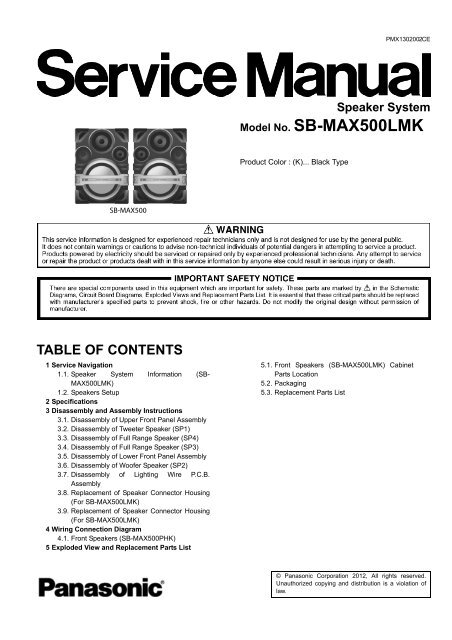
PMX1302002CE<br />
Speaker System<br />
<strong>Model</strong> <strong>No</strong>. <strong>SB</strong>-<strong>MAX500LMK</strong><br />
Product Color : (K)... Black Type<br />
<strong>SB</strong>-MAX500<br />
TABLE OF CONTENTS<br />
1 Service Navigation<br />
1.1. Speaker System Information (<strong>SB</strong>-<br />
<strong>MAX500LMK</strong>)<br />
1.2. Speakers Setup<br />
2 Specifications<br />
3 Disassembly and Assembly Instructions<br />
3.1. Disassembly of Upper Front Panel Assembly<br />
3.2. Disassembly of Tweeter Speaker (SP1)<br />
3.3. Disassembly of Full Range Speaker (SP4)<br />
3.4. Disassembly of Full Range Speaker (SP3)<br />
3.5. Disassembly of Lower Front Panel Assembly<br />
3.6. Disassembly of Woofer Speaker (SP2)<br />
3.7. Disassembly of Lighting Wire P.C.B.<br />
Assembly<br />
3.8. Replacement of Speaker Connector Housing<br />
(For <strong>SB</strong>-<strong>MAX500LMK</strong>)<br />
3.9. Replacement of Speaker Connector Housing<br />
(For <strong>SB</strong>-<strong>MAX500LMK</strong>)<br />
4 Wiring Connection Diagram<br />
4.1. Front Speakers (<strong>SB</strong>-MAX500PHK)<br />
5 Exploded View and Replacement Parts List<br />
5.1. Front Speakers (<strong>SB</strong>-<strong>MAX500LMK</strong>) Cabinet<br />
Parts Location<br />
5.2. Packaging<br />
5.3. Replacement Parts List<br />
© <strong>Panasonic</strong> Corporation 2012, All rights reserved.<br />
Unauthorized copying and distribution is a violation of<br />
law.
1 Service Navigation<br />
1.1. Speaker System Information (<strong>SB</strong>-<strong>MAX500LMK</strong>)<br />
<strong>SB</strong>-<strong>MAX500LMK</strong> is use for the following models:<br />
SC-<strong>MAX500LMK</strong><br />
1.2. Speakers Setup<br />
Conecte los bafles.<br />
Conecte los cables del bafle a las terminales del mismo color.<br />
MID MID<br />
LOW LOW HIGH LOW HIGH LOW<br />
(8 ) (8 ) (5 ) (4 ) (5 ) (4 )
2 Specifications<br />
Sección de bafles<br />
Tipo<br />
Bocina(s)<br />
Super Woofer (bajo)<br />
Super Woofer (medio bajo)<br />
Woofer<br />
Bocina para agudos<br />
Impedancia<br />
Sistema de 4 bocinas de 4 vías<br />
(reflejo de sonidos graves)<br />
Tipo cónico de 38 cm<br />
Tipo cónico de 20 cm<br />
Tipo cónico de 10 cm<br />
Tipo cónico de 6 cm<br />
5 Ω (alto), 4 Ω (medio bajo), 8 Ω (bajo)<br />
Presión acústica de salida 88 dB/W (1 m)<br />
Gama de frecuencias<br />
38 Hz a 23 kHz (–16 dB)<br />
44 Hz a 18 kHz (–10 dB)<br />
Dimensiones (An x Al x Prf)<br />
558 mm x 796 mm x 525 mm<br />
Peso<br />
31,4 kg<br />
<strong>No</strong>tes:<br />
1. Specifications are subject to change without notice.<br />
Mass and dimensions are approximate.<br />
2. Total harmonic distortion is measured by the digital spectrum analyzer.
3 Disassembly and Assembly Instructions<br />
Caution <strong>No</strong>te:<br />
• This section describes procedures for checking the operation and replacing the main components.<br />
• For reassembly after operation checks or replacement, reverse the respective procedures.<br />
• Special reassembly procedures are described only when required.<br />
• Before carrying out the disassembly process, please ensure all the safety precautions & procedures are followed.<br />
• During the disassembly and/or assembly process, please handle with care as there may be chassis components with sharp<br />
edges.<br />
• During replacement of component parts, please refer to the section of “Replacement Parts List” as described in the service manual.<br />
• Select items from the following indexes when disassembly or replacement are required.<br />
Front Speakers (<strong>SB</strong>-<strong>MAX500LMK</strong>)<br />
• Disassembly of Upper Front Panel Assembly<br />
• Disassembly of Tweeter Speaker (SP1)<br />
• Disassembly of Full Range Speaker (SP4)<br />
• Disassembly of Full Range Speaker (SP3)<br />
• Disassembly of Lower Front Panel Assembly<br />
• Disassembly of Woofer Speaker (SP2)<br />
• Disassembly of Lighting Wire P.C.B. Assembly
3.1. Disassembly of Front<br />
Panel Assembly<br />
Step 3 : Remove 2 screws.<br />
Step 1 : Remove 2 screws.<br />
Step 4 : Remove Corner Guard.<br />
Step 2 : Remove Corner Guard.
El proceso que se realizara para el desensamble podrá aplicarse, tanto para el bafle derecho como para el izquierdo de igual forma.<br />
1.- Identifique el bafle dañado que deberá ser reparado. Y prepare la 2.- Para mayor facilidad en el proceso coloque el panel en forma horizontal.<br />
herramienta que le servirá de ayuda para el proceso.<br />
1 2<br />
Y posteriormente retire los tornillos frontales que sujetan al panel.<br />
50cm min<br />
La herramienta de ayuda<br />
puede ser de cualquier<br />
material, siempre y<br />
cuando sea resistente<br />
para el proceso a realizar.<br />
10mm max<br />
8mm max<br />
Rectangualr o Circular<br />
Coloque el bafle de forma horizontal pero montado<br />
sobre unos soportes para evitar que el cable sea<br />
dañado y/o la parte posterior de el bafle se dañe.<br />
Protector (Tela)<br />
Cubra la herramienta con<br />
material suave para evitar<br />
dañar la madera y el panel<br />
(preferentemente tela)<br />
Proceda a retirar los tornillos.<br />
6 pcs<br />
3.- Retire los Corner Guard frontales e identifique los puntos de sujeción 4.- Inserte la herramienta comenzando por las cavidades que quedaron al<br />
entre el panel y el bafle para comenzar el desprendimiento.<br />
descubierto después de retirar los corner guard y comience a hacer palanca<br />
hacia la parte superior poco a poco para comenzar a desprender las guias que<br />
sujetan al panel como se muestra en las figuras (Cuatro esquinas, una a la vez).<br />
Repita estos procesos varias<br />
veces hasta que el panel se<br />
comience a desprender.<br />
2 Tornillos por cada<br />
Corner Guard.<br />
Son 10 los puntos de sujeción que<br />
tiene el panel con el Bafle como se<br />
muestra en la figura.<br />
1. <strong>No</strong> intente desprender el<br />
panel en una sola ejecución,<br />
ya que esto podría ocasionar<br />
algún daño en este (Marca de<br />
estrés o fractura en las guías).<br />
2. Al insertar la herramienta<br />
para hacer palanca, cuide los<br />
puntos de apoyo para evitar<br />
daños en las bocinas.<br />
5.- Una vez que el panel comience a desprenderce paulatinamente, 6.- Una vez desprendido el panel desconecte los cables de el Tweeter y de luz.<br />
podra insertar el herramental por los nuevos puntos abiertos y poder<br />
Desconecte el<br />
desprender mas facil el panel como se muestra en las figuras.<br />
Tweeter<br />
Parte superior, area<br />
de bocina de 20cm<br />
Partes laterales, area de<br />
Tweeter y bocina de 10cm<br />
Todos los procesos deberán ser repetitivos y con fuerza<br />
moderada hasta poder retirar el panel sin dañarlo.<br />
Desconecte el cable<br />
de luz conforme a<br />
los siguientes pasos.<br />
1. Retire la<br />
protección.<br />
2. Separe los<br />
conectores quitando<br />
el seguro.<br />
Finalmente ya retirado el<br />
panel, proceda a realizar la<br />
reparación pertinente.
80.9<br />
80.9<br />
80.9<br />
29.5<br />
122.4<br />
181.5<br />
173.1<br />
327.7<br />
185.4<br />
137.4<br />
271.5<br />
<strong>No</strong>ta: Unidades dadas en mm (solo de referencia)
3.2. Disassembly of Tweeter<br />
Speaker (SP1)<br />
• Refer to “Disassembly of Front Panel Assembly”.<br />
Step 1 : Remove 2 screws.<br />
3.3. Disassembly of Full Range<br />
Speaker (SP4)<br />
• Refer to “Disassembly of Front Panel Assembly”.<br />
Step 1 : Remove 4 screws.<br />
Step 2 : Slightly lift up Full Range Speaker (SP4) as shown.<br />
Step 3 : Detach the (+) and (-) speaker wires.<br />
Step 2 : Remove the Tweeter Speaker (SP1).
Step 4 : Remove the Full Range Speaker (SP4). 3.4. Disassembly of Full Range<br />
Speaker (SP3)<br />
• Refer to “Disassembly of Front Panel Assembly”.<br />
Step 1 : Remove 4 screws.<br />
Step 2 : Slightly lift up Full Range Speaker (SP3) as shown.<br />
Step 3 : Detach the (+) and (-) speaker wires.
Step 4 : Remove the Full Range Speaker (SP3).
3.6. Disassembly of Woofer<br />
Speaker (SP2)<br />
• Refer to “Disassembly of Upper Front Panel Assembly”.<br />
• Refer to “Disassembly of Front Ornament Assembly”.<br />
Step 1 : Remove 8 screws.<br />
Step 2 : Slightly lift up Woofer Speaker (SP2) as shown.<br />
Step 3 : Detach the (+) and (-) speaker wires.
Step 4 : Remove the Woofer Speaker (SP2). 3.7. Disassembly of Lighting Wire<br />
P.C.B. Assembly<br />
• Refer to “Disassembly of Front Panel Assembly”.<br />
• Refer to “Disassembly of Front Ornament Assembly”.<br />
Step 1 : Remove 14 screws.<br />
Step 2 : Remove 4 screws.
Step 3 : Slightly lift Front Ornament Assembly.<br />
Step 4 : Release the 4P wire from the hole of Front<br />
Panel Assembly.<br />
Caution : During assembling, inserted the 4P wire into the<br />
opening of Front Panel Assembly as diagram<br />
shown.<br />
Step 7 : Remove Lighting Wire P.C.B. Assembly.<br />
Step 5 : Remove 4 screws.<br />
Step 6 : Release the 4P wire from the slots.<br />
Caution : During assembling, ensure that the 4P wire is<br />
properly inserted into the slot.
3.8. Replacement of Speaker Connector Housing (For <strong>SB</strong>-<strong>MAX500LMK</strong>)<br />
3.8.1. Disassembly of Speaker Connector Housing<br />
Step 1: Insert a paper clip & push the Wire terminals outwards.<br />
Step 2: Detach the (+) and (-) speaker wire.<br />
Step 4: Insert the (-) speaker wire into the (-) hole of the<br />
speaker connector housing.<br />
Step 5: Push in the speaker wire until hear the “click” sound.<br />
3.8.2. Assembly of Speaker Connector<br />
Housing<br />
Step 1: Slightly lift up the wire terminals approximately 45° as<br />
shown.<br />
Step 6: Pull both speaker wires gently to ensure they lock-in<br />
firmly.<br />
<strong>No</strong>te: Repeat these procedures if the speaker wires come out.<br />
Step 2: Insert the (+) speaker wire into the (+) hole of the<br />
Speaker Connector Housing.<br />
Step 3: Push in the speaker wire until hear the “click” sound.
3.9. Replacement of Speaker Connector Housing (For <strong>SB</strong>-<strong>MAX500LMK</strong>)<br />
For Speaker wire connection, please refer to 1.2. Speaker setup<br />
3.9.1. Disassembly of Speaker Connector Housing<br />
Step 1: Insert a paper clip & push the Wire terminals outwards.<br />
Step 2: Detach the (+) and (-) speaker wire.<br />
Step 4: Insert the (-) speaker wire into the (-) hole of the<br />
speaker connector housing.<br />
Step 5: Push in the speaker wire until hear the “click” sound.<br />
3.9.2. Assembly Disassembly of Speaker<br />
Connector Housing<br />
Step 1: Slightly lift up the wire terminals approximately 45° as<br />
shown.<br />
Step 6: Pull both speaker wires gently to ensure they lock-in<br />
firmly.<br />
<strong>No</strong>te: Repeat these procedures if the speaker wires come out.<br />
Step 2: Insert the (+) speaker wire into the (+) hole of the<br />
Speaker Connector Housing.<br />
Step 3: Push in the speaker wire until hear the “click” sound.
4 Wiring Connection Diagram<br />
4.1. Front Speakers (<strong>SB</strong>-<strong>MAX500LMK</strong>)
5 Exploded View and Replacement Parts List<br />
5.1. Front Speakers (<strong>SB</strong>-<strong>MAX500LMK</strong>) Cabinet Parts Location<br />
20<br />
16<br />
SP4<br />
17<br />
6<br />
17<br />
23<br />
H<br />
G<br />
16<br />
18 18<br />
16<br />
16<br />
20<br />
16<br />
SP1<br />
d<br />
e<br />
b<br />
16<br />
a 16<br />
16<br />
17<br />
17<br />
17<br />
SP3<br />
g<br />
f<br />
21<br />
11<br />
17<br />
17<br />
6<br />
17<br />
17<br />
6<br />
17<br />
17<br />
6<br />
17<br />
4<br />
F<br />
16<br />
16<br />
5<br />
13<br />
i<br />
h<br />
8<br />
17<br />
22<br />
g<br />
f<br />
E<br />
12<br />
17<br />
17<br />
17<br />
17 17<br />
9<br />
e<br />
d<br />
17<br />
14-1<br />
D<br />
C<br />
B<br />
A<br />
19<br />
19<br />
(LIGHTING<br />
P.C.B.)<br />
ZJ6110<br />
ZJ6104<br />
(LIGHTING<br />
P.C.B.)<br />
15<br />
19<br />
15<br />
ZJ6109<br />
2<br />
15<br />
15<br />
19<br />
24<br />
1<br />
3<br />
17<br />
c<br />
17<br />
17<br />
17<br />
5<br />
17<br />
18<br />
SP2<br />
16<br />
16<br />
16<br />
16 16<br />
16<br />
16<br />
16<br />
16<br />
16<br />
16<br />
20<br />
16<br />
17<br />
16<br />
18<br />
16<br />
16<br />
16<br />
16<br />
16<br />
16<br />
16<br />
b<br />
20<br />
c<br />
i<br />
a<br />
h<br />
17<br />
7<br />
23<br />
6<br />
17<br />
17<br />
7<br />
17<br />
6<br />
14<br />
17<br />
6<br />
7<br />
17<br />
17<br />
6<br />
7<br />
14-2<br />
17<br />
<strong>SB</strong>-<strong>MAX500LMK</strong><br />
CABINET DRAWINGS<br />
22<br />
1 2 3 4 5 6 7 8 9<br />
10 11 12 13
5.2. Packaging<br />
H<br />
*P2 *P2<br />
G<br />
P3<br />
<strong>SB</strong>-<strong>MAX500LMK</strong><br />
F<br />
<strong>SB</strong>-<strong>MAX500LMK</strong><br />
P3<br />
E<br />
D<br />
*P2<br />
*P2<br />
C<br />
B<br />
P1<br />
A<br />
*P2<br />
POLYFOAM RPNM0259T (TOP)<br />
POLYFOAM RPNM0259B (BOTTOM)<br />
FRONT<br />
RPGM0280-2<br />
1 2 3 4 5 6 7 8 9<br />
<strong>SB</strong>-<strong>MAX500LMK</strong><br />
PACKAGING DRAWINGS<br />
10 11 12 13
5.3. Replacement Parts List<br />
5.3.1. Front Speakers (<strong>SB</strong>-<strong>MAX500LMK</strong>)<br />
Safety Ref. <strong>No</strong>. Part <strong>No</strong>. Part Name &<br />
Description<br />
CABINET & CHAS-<br />
SIS<br />
1 REE1737 LIGHTING WIRE 1<br />
PCB ASS’Y<br />
2 RGK2430-SL FRONT ORNAMENT 1<br />
3 RGL0781-QL LIGHTING PIECE 1<br />
4 RQLM0445 SPEC LABEL (L) 1<br />
4 RQLM0444 SPEC LABEL (R) 1<br />
5 RYPM0317 FRONT PANEL 1<br />
6 RGQ0708-KL CORNER GUARD 8<br />
7 RKAX0042-K LEG RUBBER 4<br />
8 RMQ0819 EVA PACKING 1<br />
9 RMQM0175 EVA PACKING 1<br />
11 RMQM0174 EVA PACKING 1<br />
12 RYQ1114-KL NET FRAME ASSY 1<br />
(WOOFER)<br />
13 RYPM0318 TWEETER HOLDER 1<br />
ASSY<br />
14 RKPM0152 WOODEN BOX ASSY 1<br />
(L)<br />
14 RKPM0151 WOODEN BOX ASSY<br />
(R)<br />
1<br />
Qty Remarks<br />
Safety Ref. <strong>No</strong>. Part <strong>No</strong>. Part Name & Qty Remarks<br />
Description<br />
14-1 K1MY04A00003 4P SPK CONNEC- 1<br />
TOR HOUSING<br />
WHITE (L)<br />
14-1 K1MY04A00004 4P SPK CONNEC- 1<br />
TOR HOUSING RED<br />
(R)<br />
14-2 KN-MSA-22-02 2P SPK CONNEC- 1<br />
LF(P8)<br />
TOR HOUSING<br />
WHITE (L)<br />
14-2 KN-MSA-22-01 2P SPK CONNEC- 1<br />
LF(P8)<br />
TOR HOUSING RED<br />
(R)<br />
15 XTB3+12GFJ SCREW 4<br />
16 XTB4+12GFJ SCREW 30<br />
17 XTB4+16AFJK SCREW 33<br />
18 XTB4+20AFJK SCREW 4<br />
19 RMQM0188 HIMELON 4<br />
20 RMQM0182 HIMELON 4<br />
21 RMR2103-KL WOOFER SPACER 1<br />
22 RMQM0187 HIMELON 2<br />
23 RMQM0186 HIMELON 2<br />
24 RMQM0189 HIMELON 1<br />
SPEAKERS<br />
SP1 EAS6PH124K TWEETER 1<br />
SP2 L0AA38A00006 WOOFER SPEAKER 1<br />
SP3 L0AA20A00021 SPEAKER 1<br />
SP4 EAS10P661B SPEAKER 1
5.3.2. Packing Materials<br />
Safety Ref. <strong>No</strong>. Part <strong>No</strong>. Part Name &<br />
Description<br />
Qty Remarks<br />
PACKING MATERI-<br />
ALS<br />
P1 RPGM0280-2 PACKING CASE 1<br />
P2 RPNM0259T/B POLYFOAM 2<br />
P3 RPFM0064/-R MIRAMAT BAG 2


