DMC-FT20EE DMC-FT20EF DMC-FT20EG DMC ... - Panasonic
DMC-FT20EE DMC-FT20EF DMC-FT20EG DMC ... - Panasonic
DMC-FT20EE DMC-FT20EF DMC-FT20EG DMC ... - Panasonic
You also want an ePaper? Increase the reach of your titles
YUMPU automatically turns print PDFs into web optimized ePapers that Google loves.
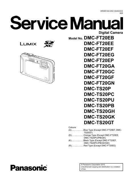
ORDER NO.DSC1202003CEB26Digital CameraModel No. <strong>DMC</strong>-FT20EB<strong>DMC</strong>-<strong>FT20EE</strong><strong>DMC</strong>-<strong>FT20EF</strong><strong>DMC</strong>-<strong>FT20EG</strong><strong>DMC</strong>-FT20EP<strong>DMC</strong>-FT20GA<strong>DMC</strong>-FT20GC<strong>DMC</strong>-FT20GF<strong>DMC</strong>-FT20GN<strong>DMC</strong>-TS20P<strong>DMC</strong>-TS20PC<strong>DMC</strong>-TS20PU<strong>DMC</strong>-TS20PB<strong>DMC</strong>-TS20GH<strong>DMC</strong>-TS20GK<strong>DMC</strong>-TS20GTColours(A)....................Blue Type (Except <strong>DMC</strong>-<strong>FT20EF</strong>, <strong>DMC</strong>-TS20GT)(D)....................Orange Type (Except <strong>DMC</strong>-<strong>FT20EE</strong>,<strong>DMC</strong>-TS20PU/PB/GK)(K)....................Black Type (Except <strong>DMC</strong>-<strong>FT20EF</strong>,<strong>DMC</strong>-TS20PC/PB/GH/GK)(R)....................Red Type (Except <strong>DMC</strong>-<strong>FT20EE</strong>)© <strong>Panasonic</strong> Corporation 2012.Unauthorized copying and distribution is a violationof law.
TABLE OF CONTENTSPAGE1 Safety Precautions -----------------------------------------------31.1. General Guidelines ----------------------------------------31.2. Leakage Current Cold Check ---------------------------31.3. Leakage Current Hot Check (See Figure 1)---------31.4. How to Discharge the Capacitor on FlashP.C.B.----------------------------------------------------------42Warning--------------------------------------------------------------52.1. Prevention of Electrostatic Discharge (ESD)to Electrostatic Sensitive (ES) Devices---------------52.2. How to Recycle the Lithium Ion Battery (U.S.Only)-----------------------------------------------------------52.3. Caution for AC Cord (For EB/GC/GH) ----------------62.4. How to Replace the Lithium Battery-------------------73 Service Navigation------------------------------------------------93.1. Introduction --------------------------------------------------93.2. Air-leak test (inspection)----------------------------------93.3. Replacing the waterproof packing (waterproofseal) -----------------------------------------------------------93.4. Camera Lens Unit------------------------------------------93.5. General Description About Lead Free Solder(PbF) -------------------------------------------------------- 103.6. How to Define the Model Suffix (NTSC or PALmodel)------------------------------------------------------- 114 Specifications ---------------------------------------------------- 155 Location of Controls and Components------------------ 206 Service Mode ----------------------------------------------------- 226.1. Error Code Memory Function ------------------------- 226.2. ICS (Indication of additional Camera Settingswhen picture was taken) function -------------------- 257 Troubleshooting Guide---------------------------------------- 277.1. Service and Check Procedures ---------------------- 277.2. Air-leak Test ----------------------------------------------- 308 Service Fixture & Tools --------------------------------------- 328.1. Service Fixture and Tools ------------------------------ 328.2. When Replacing the Main P.C.B. -------------------- 338.3. Service Position ------------------------------------------ 339 Disassembly and Assembly Instructions--------------- 349.1. Disassembly Flow Chart-------------------------------- 349.2. P.C.B. Location ------------------------------------------- 349.3. Disassembly Procedures------------------------------- 3510 Measurements and Adjustments -------------------------- 4410.1. Introduction ------------------------------------------------ 4410.2. Before Disassembling the unit ------------------------ 4410.3. Details of Electrical Adjustment----------------------- 4610.4. After Adjustment------------------------------------------ 5011 Maintenance ------------------------------------------------------ 5111.1. Cleaning Lens and LCD Panel ----------------------- 5112 Block Diagram --------------------------------------------------- 5312.1. Overall Block Diagram ---------------------------------- 5312.2. System Control Block Diagram ----------------------- 5412.3. Video/Audio Signal Process Block Diagram------- 5512.4. Sensor Block Diagram ---------------------------------- 56PAGE12.5. Lens Drive Block Diagram----------------------------- 5712.6. Power Block Diagram----------------------------------- 5813 Wiring Connection Diagram -------------------------------- 5913.1. Interconnection Diagram------------------------------- 592
1 Safety Precautions1.1. General Guidelines1. IMPORTANT SAFETY NOTICEThere are special components used in this equipmentwhich are important for safety. These parts are marked byin the Schematic Diagrams, Circuit Board Layout,Exploded Views and Replacement Parts List. It isessential that these critical parts should be replaced withmanufacturer's specified parts to prevent X-RADIATION,shock fire, or other hazards. Do not modify the originaldesign without permission of manufacturer.2. An Isolation Transformer should always be used duringthe servicing of AC Adaptor whose chassis is not isolatedfrom the AC power line. Use a transformer of adequatepower rating as this protects the technician fromaccidents resulting in personal injury from electricalshocks. It will also protect AC Adaptor from beingdamaged by accidental shorting that may occur duringservicing.3. When servicing, observe the original lead dress. It a shortcircuit is found, replace all parts which have beenoverheated or damaged by the short circuit.4. After servicing, see to it that all the protective devicessuch as insulation barriers, insulation papers shields areproperly installed.5. After servicing, make the following leakage currentchecks to prevent the customer from being exposed toshock hazards.1.2. Leakage Current Cold Check1. Unplug the AC cord and connect a jumper between thetwo prongs on the plug.2. Measure the resistance value, with an ohmmeter,between the jumpered AC plug and each exposedmetallic cabinet part on the equipment such asscrewheads, connectors, control shafts, etc. When theexposed metallic part has a return path to the chassis, thereading should be between 1MΩ and 5.2MΩ. When theexposed metal does not have a return path to the chassis,the reading must be infinity.1.3. Leakage Current Hot Check(See Figure 1)1. Plug the AC cord directly into the AC outlet. Do not usean isolation transformer for this check.2. Connect a 1.5kΩ, 10 W resistor, in parallel with a 0.15μFcapacitor, between each exposed metallic part on the setand a good earth ground, as shown in Figure 1.3. Use an AC voltmeter, with 1 kΩ/V or more sensitivity, tomeasure the potential across the resistor.4. Check each exposed metallic part, and measure thevoltage at each point.5. Reverse the AC plug in the AC outlet and repeat each ofthe above measurements.6. The potential at any point should not exceed 0.75 V RMS.A leakage current tester (Simpson Model 229 orequivalent) may be used to make the hot checks, leakagecurrent must not exceed 1/2 mA. In case a measurementis outside of the limits specified, there is a possibility of ashock hazard, and the equipment should be repaired andrechecked before it is returned to the customer.Figure 13
1.4. How to Discharge the Capacitor on Flash P.C.B.• This unit equipped with two pieces of capacitors as flash charging capacitors."Either one of the capacitor discharging operation" makes discharging for others as well.CAUTION:1. Be sure to discharge the capacitor on Flash P.C.B.2. Be careful of the high voltage circuit on Flash P.C.B. when servicing.[Discharging Procedure]1. Refer to the disassemble procedure and remove the necessary parts/unit.2. Put the insulation tube onto the lead part of Resistor (ERG5SJ102:1kΩ /5W).(An equivalent type of resistor may be used.)3. Put the resistor between both terminals of capacitor on Flash P.C.B. for approx. 5 seconds.4. After discharging confirm that the capacitor voltage is lower than 10V using a voltmeter.Fig. F14
2 Warning2.1. Prevention of Electrostatic Discharge (ESD) to Electrostatic Sensitive(ES) DevicesSome semiconductor (solid state) devices can be damaged easily by static electricity. Such components commonly are calledElectrostatically Sensitive (ES) Devices.The following techniques should be used to help reduce the incidence of component damage caused by electrostatic discharge(ESD).1. Immediately before handling any semiconductor component or semiconductor-equipped assembly, drain off any ESD on yourbody by touching a known earth ground. Alternatively, obtain and wear a commercially available discharging ESD wrist strap,which should be removed for potential shock reasons prior to applying power to the unit under test.2. After removing an electrical assembly equipped with ES devices, place the assembly on a conductive surface such asaluminum foil, to prevent electrostatic charge buildup or exposure of the assembly.3. Use only a grounded-tip soldering iron to solder or unsolder ES devices.4. Use only an antistatic solder removal device. Some solder removal devices not classified as cangenerate electrical charge sufficient to damage ES devices.5. Do not use freon-propelled chemicals. These can generate electrical charges sufficient to damage ES devices.6. Do not remove a replacement ES device from its protective package until immediately before you are ready to install it. (Mostreplacement ES devices are packaged with leads electrically shorted together by conductive foam, aluminum foil orcomparable conductive material).7. Immediately before removing the protective material from the leads of a replacement ES device, touch the protective materialto the chassis or circuit assembly into which the device will be installed.CAUTION:Be sure no power is applied to the chassis or circuit, and observe all other safety precautions.8. Minimize bodily motions when handling unpackaged replacement ES devices. (Otherwise harmless motion such as thebrushing together of your clothes fabric or the lifting of your foot from a carpeted floor can generate static electricity (ESD)sufficient to damage an ES device).2.2. How to Recycle the Lithium Ion Battery (U.S. Only)5
2.3. Caution for AC Cord (For EB/GC/GH)2.3.1. Information for Your SafetyIMPORTANTYour attention is drawn to the fact that recording of prerecordedtapes or discs or other published or broadcastmaterial may infringe copyright laws.WARNINGTo reduce the risk of fire or shock hazard, do not exposethis equipment to rain or moisture.CAUTIONTo reduce the risk of fire or shock hazard and annoyinginterference, use the recommended accessories only.FOR YOUR SAFETYDO NOT REMOVE THE OUTER COVERTo prevent electric shock, do not remove the cover. No userserviceable parts inside. Refer servicing to qualified servicepersonnel.2.3.2. Caution for AC Mains LeadFor your safety, please read the following text carefully.This appliance is supplied with a moulded three-pin mains plugfor your safety and convenience.A 5-ampere fuse is fitted in this plug.Should the fuse need to be replaced please ensure that thereplacement fuse has a rating of 5 amperes and it is approvedby ASTA or BSI to BS1362Check for the ASTA mark or the BSI mark on the body of thefuse.2.3.2.1. ImportantThe wires in this mains lead are coloured in accordance withthe following code:BlueBrownNeutralLiveAs the colours of the wires in the mains lead of this appliancemay not correspond with the coloured markings identifying theterminals in your plug, proceed as follows:The wire which is coloured BLUE must be connected to theterminal in the plug which is marked with the letter N orcoloured BLACK.The wire which is coloured BROWN must be connected to theterminal in the plug which is marked with the letter L or colouredRED.Under no circumstances should either of these wires beconnected to the earth terminal of the three pin plug, markedwith the letter E or the Earth Symbol.2.3.2.2. Before Useremove the Connector Cover as follows.If the plug contains a removable fuse cover you must ensurethat it is refitted when the fuse is replaced.If you lose the fuse cover, the plug must not be used until areplacement cover is obtained.A replacement fuse cover can be purchased from your local<strong>Panasonic</strong> Dealer.2.3.2.3. How to Replace the Fuse1. Remove the Fuse Cover with a screwdriver.If the fitted moulded plug is unsuitable for the socket outlet inyour home then the fuse should be removed and the plug cutoff and disposed of safety.There is a danger of severe electrical shock if the cut off plug isinserted into any 13-ampere socket.If a new plug is to be fitted please observe the wiring code asshown below.If in any doubt, please consult a qualified electrician.2. Replace the fuse and attach the Fuse cover.6
2.4. How to Replace the Lithium Battery2.4.1. Replacement Procedure1. Remove the Main P.C.B. (Refer to Disassembly Procedures.)2. Unsolder the Lithium battery (Ref. No. at foil side of Main P.C.B.) and then replace it into new one.Note:The lithium battery is a critical component.(Type No.: ML-421S/DN Manufactured by Energy Company, <strong>Panasonic</strong> Corporation)It must never be subjected to excessive heat or discharge.It must therefore only be fitted in equipment designed specifically for its use.Replacement batteries must be of the same type and manufacture.They must be fitted in the same manner and location as the original battery, with the correct polarity contacts observed.Do not attempt to re-charge the old battery or re-use it for any other purpose.It should be disposed of in waste products destined for burial rather than incineration.7
Note:Above caution is applicable for a battery pack which is for <strong>DMC</strong>-FT20 and <strong>DMC</strong>-TS20 series, as well.Danger of explosion if battery is incorrectly replaced.Replace only with the same or equivalent type recommended by the manufacturer.Dispose of used batteries according to the manufacturer's instructions.8
3 Service Navigation3.1. IntroductionThis service manual contains technical information, which will allow service personnel's to understand and service this model.Please place orders using the parts list and not the drawing reference numbers.If the circuit is changed or modified, the information will be followed by service manual to be controlled with original service manual.3.2. Air-leak test (inspection)Waterproof/Dustproof PerformanceThis camera's waterproof/dustproof rating complies with the "IPX8" and "IP6X" ratings. Provided the care and maintenance guidelinesdescribed in this document are strictly followed, this camera can operate underwater, to a depth not exceeding 5 m (16 feet) for a timenot exceeding 60 minutes. (*1)Anti-shock PerformanceThis camera also complies with "MIL-STD 810F Method 516.5-Shock". The camera has cleared a drop test from a height of 1.5 m (5feet) onto 3 cm (0.1 feet) thick plywood. In most cases this camera should not sustain any damage if dropped from a height notexceeding 1.5 m (5 feet). (*2)This does not guarantee no destruction, no malfunction, or waterproofing in all conditions.*1 This means that the camera can be used underwater for specified time in specified pressure in accordance with the handlingmethod established by <strong>Panasonic</strong>.*2 "MIL-STD 810F Method 516.5-Shock" is the test method standard of the U.S. Defense Department, which specifiesperforming drop tests from a height of 122 cm (4 feet), at 26 orientations (8 corners, 12 ridges, 6 faces) using 5 sets of devices,and passing the 26 orientation drops within 5 devices. (If failure occurs during the test, a new set is used to pass the droporientation test within a total of 5 devices)<strong>Panasonic</strong>’s test method is based on the above "MIL-STD 810F Method 516.5-Shock". However, the drop height was changedfrom 122 cm (4.0 feet) to 150 cm (5 feet) dropping onto 3 cm (0.1 feet) thick plyboard. This drop test was passed.(Disregarding appearance change such as loss of paint or distortion of the part where drop impact is applied.)• Due to the above characteristics of the products, perform the air-leak test (inspection) using Air -leak tester (Part No.:RFKZ0528)before/after servicing including assembly and/or assembly process.Note:The purpose of the air-leak test before servicing is that whether the malfunction occurred due to air-leak or not.• When servicing, refer to the "7.Troubleshooting" section for details.3.3. Replacing the waterproof packing (waterproof seal)• The integrity of the waterproof packing may decrease about 1 year, with use and age.(We recommend end users to replace the waterproof packing (waterproof seal) at least once each year described in theoperating instructions.)• As for replacement procedure, refer to the 7.1.2. Periodical maintenance (Packing replacement) flow for details.3.4. Camera Lens Unit• Since the lens unit for this model is assembled with high accuracy manufacturing technologies, it is not allowed to disassemble/assemble the lens unit, in terms of performance retention.When servicing, it has to be handled the "Camera Lens Unit" as the smallest part size.Confirm the replacement part list and exploded views for details.9
3.5. General Description About Lead Free Solder (PbF)The lead free solder has been used in the mounting process of all electrical components on the printed circuit boards used for thisequipment in considering the globally environmental conservation.The normal solder is the alloy of tin (Sn) and lead (Pb). On the other hand, the lead free solder is the alloy mainly consists of tin(Sn), silver (Ag) and Copper (Cu), and the melting point of the lead free solder is higher approx.30 °C (86 °F) more than that of thenormal solder.Definition of P.C.B. Lead Free Solder being usedThe letter of is printed either foil side or components side on the P.C.B. using the lead free solder.(See right figure)Service caution for repair work using Lead Free Solder (PbF)• The lead free solder has to be used when repairing the equipment for which the lead free solder is used.• (Definition: The letter of is printed on the P.C.B. using the lead free solder.)• To put lead free solder, it should be well molten and mixed with the original lead free solder.• Remove the remaining lead free solder on the P.C.B. cleanly for soldering of the new IC.• Since the melting point of the lead free solder is higher than that of the normal lead solder, it takes the longer time to melt thelead free solder.• Use the soldering iron (more than 70W) equipped with the temperature control after setting the temperature at 350±30 degreesC (662±86 °F).Recommended Lead Free Solder (Service Parts Route.)• The following 3 types of lead free solder are available through the service parts route.RFKZ03D01KS-----------(0.3mm 100g Reel)RFKZ06D01KS-----------(0.6mm 100g Reel)RFKZ10D01KS-----------(1.0mm 100g Reel)Note* Ingredient: tin (Sn) 96.5%, silver (Ag) 3.0%, Copper (Cu) 0.5%, Cobalt (Co) / Germanium (Ge) 0.1 to 0.3%10
3.6. How to Define the Model Suffix (NTSC or PAL model)There are eight kinds of <strong>DMC</strong>-FT20/TS20, regardless of the colours.• a) <strong>DMC</strong>-FT20 (Japan domestic model.)• b) <strong>DMC</strong>-TS20P/PC• c) <strong>DMC</strong>-FT20EB/EF/EG/EP• d) <strong>DMC</strong>-<strong>FT20EE</strong>• e) <strong>DMC</strong>-TS20GT• f ) <strong>DMC</strong>-FT20GN• g) <strong>DMC</strong>-TS20GK• h) <strong>DMC</strong>-FT20GA/GC/GF, <strong>DMC</strong>-TS20GH/PB/PUWhat is the difference is that the "INITIAL SETTINGS" data which is stored in Flash ROM mounted on Main P.C.B.3.6.1. Defining methodsTo define the model suffix to be serviced, refer to the nameplate which is putted on the bottom side of the Unit.Note:After replacing the Main P.C.B., be sure to achieve adjustment.The Maintenance software (DIAS) is available at "software download" on the "Support Information from NWBG/VDBG-AVC"web-site in "TSN system".11
3.6.2. INITIAL SETTINGS:After replacing the Main P.C.B., be sure to perform the initial settings after achieving the adjustment by ordering the followingprocedure in accordance with model suffix of the unit.1. IMPORTANT NOTICE:Before proceeding Initial settings, be sure to read the following CAUTIONS.2. PROCEDURES:• Precautions: Read the above "CAUTION 1" and "CAUTION 2", carefully• Preparation:1. Attach the Battery to the unit.2. Set to NORMAL PICTURE mode by operating the mode button.Note:If the picture mode is other than NORMAL PICTURE mode, it does not display the initial settings menu.• Step 1. The temporary cancellation of "INITIAL SETTINGS":While keep pressing "UP of Cursor button" and MOTION PICTURE button simultaneously, turn the Power on.• Step 2. The cancellation of "INITIAL SETTINGS":Press the PLAYBACK button.Press "UP of Cursor button" and MOTION PICTURE button simultaneously, then turn the Power off.• Step 3. Turn the Power on:Turn the Power on.• Step 4. Display the "INITIAL SETTINGS" menu:While keep pressing MENU/SET and "RIGHT of Cursor button" simultaneously, turn the Power off.The "INITIAL SETTINGS" menu is displayed.There are two kinds of "NITIAL SETTINGS" menu form as follows:[CASE 1. After replacing Main P.C.B.]When Main P.C.B. has just been replaced, the following model suffix list is displayed as follows. (Six pages in total)12
[CASE 2. Other than "After replacing Main P.C.B."]• Step 5. Choose the model suffix in "INITIAL SETTINGS": (Refer to "CAUTION 1")[Caution: After replacing Main P.C.B.](Especially, other than "EG, EF, EB and EP" models)The model suffix can be chosen, JUST ONE TIME.Once one of the model suffix have been chosen, the model suffix lists will not be displayed, thus, it can be changed.Therefore, select the area carefully.Select the area with pressing "UP / DOWN of Cursor buttons".• Step 6. Set the model suffix at "INITIAL SETTINGS":Press the "RIGHT of Cursor buttons".The only set area is displayed. Press the "RIGHT of Cursor buttons" after confirmation.(The unit is powered off automatically.)13
• Step 7. CONFIRMATION:Confirm the display of "PLEASE SET THE CLOCK" in concerned language when the unit is turned on again.When the unit is connected to PC with USB cable, it is detected as removable media.1) As for your reference, major default setting condition is as shown in the following table.Default setting (After "INITIAL SETTINGS")MODEL VIDEO OUTPUT LANGUAGE DATE REMARKSa) <strong>DMC</strong>-FT20(Japan domestic model) NTSC Japanese Year/Month/Dateb) <strong>DMC</strong>-FT20EB PAL English Date/Month/Yearc) <strong>DMC</strong>-<strong>FT20EE</strong> PAL Russian Date/Month/Yeard) <strong>DMC</strong>-<strong>FT20EF</strong> PAL French Date/Month/Yeare) <strong>DMC</strong>-<strong>FT20EG</strong> PAL English Date/Month/Yearf) <strong>DMC</strong>-FT20EP PAL English Date/Month/Yearg) <strong>DMC</strong>-FT20GA PAL English Date/Month/Yearh) <strong>DMC</strong>-FT20GC PAL English Date/Month/Yeari) <strong>DMC</strong>-FT20GF PAL English Date/Month/Yearj) <strong>DMC</strong>-FT20GN PAL English Date/Month/Yeark) <strong>DMC</strong>-TS20GH PAL English Date/Month/Yearl) <strong>DMC</strong>-TS20GK PAL Chinese (Simplified) Year/Month/Datem) <strong>DMC</strong>-TS20GT NTSC Chinese (Traditional) Year/Month/Daten) <strong>DMC</strong>-TS20P NTSC English Date/Month/Yearo) <strong>DMC</strong>-TS20PC NTSC English Date/Month/Yearp) <strong>DMC</strong>-TS20PU NTSC Spanish Date/Month/Yearq) <strong>DMC</strong>-TS20PB NTSC Spanish Date/Month/Year14
4 Specifications15
Note:*Above specification is for <strong>DMC</strong>-TS20P. Some of the specification may differ depends on model suffix.[1] Only for "EB/EF/EG/EP" models:1). [Interface Digital:]• Data from the PC can not be written to the camera using the USB connection cable.[2] Others:1). [Analog video/audio:]NTSC ----------------------------------------------------------(Only "P/PC" models)NTSC/PAL Composite (Switched by menu) ----------(Except "P/PC" models)16
5 Location of Controls and Components20
6 Service Mode6.1. Error Code Memory Function1. General descriptionThis unit is equipped with history of error code memory function, and can be memorized 16 error codes in sequence from thelatest. When the error is occurred more than 16, the oldest error is overwritten in sequence.The error code is not memorized when the power supply is shut down forcibly (i.e.,when the unit is powered on by the battery,the battery is pulled out) The error code is memorized to FLASH ROM when the unit has just before powered off.2. How to displayThe error code can be displayed by ordering the following procedure:• Preparation:1. Attach the Battery to the unit.Note:*Since this unit has built-in memory, it can be performed without inserting SD memory card.*Select the mode other than "3D" mode (such as normal picture / iA / Sports / Snow / SCN)to display the error code.• Step 1. The temporary cancellation of "INITIAL SETTINGS":While keep pressing "UP of Cursor button" and MOTION PICTURE button simultaneously, turn the Power on.• Step 2. Execute the error code display mode:Press the "LEFT of Cursor button", MENU/SET button and MOTION PICTURE button simultaneously.The display is changed as shown below when the above buttons are pressed simultaneously.Normal display → Error code display → CAMERA INFO → Normal display → .....22
3. Error Code ListThe error code consists of 8 bits data and it shows the following information.Attribute Main item Sub item Error code Contents (Upper) Error IndicationHigh 4bits Low 4 bits Check point (Lower) Detecting Part/CircuitdeviceLENS Lens drive OIS 18*0 1000 PSD (X) error. Hall element (X axis) position detect OIS X LENSu NGerror in OIS unit.OIS Unit2000 PSD (Y) error. Hall element (Y axis) position detect OIS Yerror in OIS unit.OIS Unit3000 GYRO (X) error. Gyro (IC7101) detect error on Main GYRO X GYRO NGP.C.B.IC7101 (Gyro element) or IC6001 (VENUS ENGINE)4000 GYRO (Y) error. Gyro (IC7101) detect error on Main GYRO YP.C.B.IC6302 (Gyro element) or IC6001 (VENUS ENGINE)5000 MREF error (Reference voltage error). OIS REF LENSSd/DSPIC9101 (LENS DRIVE) or IC6001 (VENUS ENGINE)NG6000 Drive voltage (X) error. OISX REF LENSu/LENSLENS Unit, LENS flex breaks, IC6001(VENUSENGINE) AD value error, etc.FPC7000 Drive voltage (Y) error. OISY REFLENS Unit, LENS flex breaks, IC6001(VENUSENGINE) AD value error, etc.Zoom 0?10 Collapsible barrel Low detect error(Collapsible barrel encoder always detects Low.)ZOOM L ZOOMm/LENSuMechanical lock, FP9003-(2) signal line or IC6001(VENUS ENGINE)0?20 Collapsible barrel High detect errorZOOM H(Collapsible barrel encoder always detects High.)Mechanical lock, FP9003-(2) signal line or IC6001(VENUS ENGINE)0?60 The zoom position jump is detected due to theimpact (i.e. drop.) to the camera occurs.(No indication) (No indication)Lens unitFocus 0?01 HP High detect error(Focus encoder always detects High, and notbecomes Low)Mechanical lock, FP9003-(40) signal line or IC6001(VENUS ENGINE)0?02 HP Low detect error(Focus encoder always detects Low, and notbecomes High)FOCUS LFOCUS HLENS FPC/DSPMechanical lock, FP9002-(40) signal line or IC6001(VENUS ENGINE)Lens 18*1 0000 Power ON time out error. LENS DRV LENSuLens drive system18*2 0000 Power OFF time out error.Lens drive systemAdj.History OIS 19*0 2000 OIS adj. Yaw direction amplitude error (small) OIS ADJ OIS ADJ3000 OIS adj. Pitch direction amplitude error (small)4000 OIS adj. Yaw direction amplitude error (large)5000 OIS adj. Pitch direction amplitude error (large)6000 OIS adj. MREF error7000 OIS adj. time out error8000 OIS adj. Yaw direction off set error9000 OIS adj. Pitch direction off set errorA000 OIS adj. Yaw direction gain errorB000 OIS adj. Pitch direction gain errorC000 OIS adj. Yaw direction position sensor errorD000 OIS adj. Pitch direction position sensor errorE000 OIS adj. other error23
Attribute Main item Sub item Error code Contents (Upper) Error IndicationHARD VENUS A/DFLASHROM(EEPROMArea)High 4bits Low 4 bits Check point (Lower) Detecting Part/CircuitdeviceFlash 28*0 0000 Flash charging error. STRB CHG FLASH P.C.B./IC6001-(AC16) signal line or Flash charging circuitFPCFLASHROM(EEPROMArea)2B*0 0001 EEPROM read error FROM RE FROM00030004 IC6002 (FLASH ROM)0002 EEPROM write error FROM WR FROMIC6002 (FLASH ROM)0005 Firmware version up error (No indication) (No indication)Replace the firmware file in the SD memory card.0008 SDRAM error0009 SDRAM Mounting defectiveSYSTEM RTC 2C*0 0001 SYSTEM IC initialize failure error SYS INIT MAIN P.C.B.Communication between IC6001 (VENUS ENGINE)and IC9101 (SYSTEM)SOFT CPU Reset 30*0 0001|0007NMI resetNon Mask-able Interrupt(30000001-30000007 are caused by factors)NMI RSTMAIN P.C.B.Card Card 31*0 0001 Card logic error SD CARD SD CARD/SD memory card data line or IC6001 (VENUSENGINE)DSP0002 Card physical errorSD memory card data line or IC6001 (VENUSENGINE)0004 Write error SD WRITESD memory card data line or IC6001 (VENUSENGINE)39*0 0005 Format error INMEMORY FROMCPU, Stop 38*0 0001 Camera task finish process time out. LENS COM LENSu/DSPASIC hardCommunication between Lens system and IC6001(VENUS ENGINE)0002 Camera task invalid code error. DSP DSPIC6001 (VENUS ENGINE)0100 File time out error in recording motion imageIC6001 (VENUS ENGINE)0200 File data cue send error in recording motion imageIC6001 (VENUS ENGINE)0300 Single or burst recording brake time out.Memoryarea3A*0 0008 USB work area partitioning failure (No indication) (No indication)USB dynamic memory securing failure whenconnectingOperation Power on 3B*0 0000 FLASHROM processing early period of cameraINIT (No indication)during movement.Zoom Zoom 3C*0 0000 Imperfect zoom lens processing ZOOM ZOOMm/Zoom lensLENSu35*0 0000|FFFFSoftware error(0-7bit : command, 8-15bit : status)35*1 0000 Though record preprocessing is necessary, it is notcalled.35*2 0000 Though record preprocessing is necessary, it is notcompleted.1) About "*" indication:The third digit from the left is different as follows.In case of 0 (example: 18 0 01000)When the third digit from the left shows "0", this error occurred under the condition of INITIAL SETTINGS has been completed.It means that this error is occurred basically at user side.In case of 8 (example: 18 8 01000)When the third digit from the left shows "8", this error occurred under the condition of INITIAL SETTINGS has been released.(Example; Factory assembling-line before unit shipment, Service mode etc.)It means that this error is occurred at service side.2) About "?" indication: ("18*0 0?01" to "18*0 0?50"):The third digit from the right shows one of the hexadecimal ("0" to "F") character.DSPDSP(No indication) (No indication)24
4. How to returned to Normal Display:Turn the power off and on, to exit from Error code display mode.Note:The error code can not be initialized.6.2. ICS (Indication of additional Camera Settings when picture was taken)function1. General descriptionThis unit is equipped with ICS (ICS : Indication of additional Camera Settings when picture was taken) function by playing back theconcerned picture on the LCD display.(This function is achieved by utilizing "maker note" data stored in Exif data area of recorded picture file.)To proceed failure diagnosis, use this ICS function together with "displaying the recorded picture with picture information" function.Note:*.The ICS function operates with a picture which is only taken with the same model. (It may not be displayed when the picturewas taken with other model.)*.Since Exif data is not available after the picture is edited by PC, the ICS function may not be activated.2. How to displayThe ICS data is displayed by ordering the following procedure:• Preparation:1.Attach the Battery to the unit.Note:*Select the mode other than "3D "mode (such as normal picture / iA / Sports / Snow / SCN) to display the ICS data.• Step 1. The temporary cancellation of "INITIAL SETTINGS":While keep pressing "UP of Cursor button" and MOTION PICTURE button simultaneously, turn the Power on.• Step 2. Execute the ICS display mode:Press the PLAYBACK button.Select the concerned picture by pressing the "LEFT and RIGHT of Cursor button".Press the MENU/SET button, "LEFT of Cursor button" and MOTION PICTURE button simultaneously.Press the DISPLAY button, 3 times.The display condition is changed as shown below when the DISPLAY button is pressed.Code display → Code + Picture display (1) → Code + Picture display (2) → ICS display → .....25
3. How to read4. How to exitSimply, turn the power off. (Since ICS function is executed under the condition of temporary cancellation of "INITIAL SETTINGS",itwake up with normal condition when turn off the power.)26
7 Troubleshooting Guide7.1. Service and Check Procedures7.1.1. Servicing flow• The following is the servicing procedure including assembly/disassembly process.• As for the air-leak test, refer to "7.2. Air-leak Test".< Note >Air-leak test (inspection) before taking service measure:• When the first inspection, do not perform cleaning (removal of foreign objects caught etc.) of the waterproof packing parts(battery door and Jack door) from the viewpoint of the cause investigation at NG of test (inspection) result.• When the test (inspection) result was NG, perform test again after cleaning of waterproof packing parts.27
7.1.2. Periodical maintenance (Packing replacement) flow• The integrity of the waterproof packings may decrease about 1 year, with use and age.(We recommend end-users to replace the waterproof packing at least once each year described in the operating instructions.)• Please use waterproof packing kit (Part No.: VUMG2032). (5 types, 6 packings in total are included)• Do not touch the waterproof packings directly by the hand.• Do not perform cleaning of waterproof packings by the solvent of alcohol etc. or by blowing air.• Take care not to put any foreign objects (garbage and dust).• As for the air-leak test, refer to "7.2. Air-leak Test".28
Replacing the waterproof packing• The location of waterproof packing are shown at right. (5 types, 6 packings in total)• Waterproof packings are supplied as Waterproof packing kit (Part No.: VUMG2032).< Note for replacement >• Do not touch the waterproof packings directly by the hand.• Do not perform cleaning of waterproof packings by the solvent of alcohol etc. or by blowing air.• Take care not to put any foreign objects (garbage and dust).• Use the silicon chips (Part No.: RFKZ0478) when replacing the Case O-ring.29
7.2. Air-leak TestDue to the waterproof performance retention, perform the air-leak test using Air-leak tester (Part No.:RFKZ0528) before/afterservicing when disassembling and assembling the unit.*The Air-leak test before servicing is necessary to be performed to check whether the malfunction occurred due to air-leak or not.1. Preparation:1) By referring the "9.3. Disassembly procedures", remove the side ornament R and front almi case unit.2) Confirm that no foreign objects at the side door, and it is firmly closed.2. Air-leak Test (Inspection):*Perform the air-leak test by referring the following procedure.Note:As for the detail instruction of air-leak tester, refer to the operating guide (attached to the product).[Preparation]1. Put the camera with the top case facing upward condition.2. Set the following measurement pressure value on the air-leak tester. (Part No.:RFKZ0528).*About the Setting methods, refer to the operating guide for air-leak tester.3. Attach "L" size of absorption pad to the tip of the hose of the air-leak tester.4. Put the absorption pad of air-leak tester vertically on the Inspection point.Note:• Keep firmly hold above condition until the measurement is completed.Once pad is tilted/misaligned from the test hole during testing process, start it from this step.30
Measuring condition (For <strong>DMC</strong>-FT20, <strong>DMC</strong>-TS20)*Attach "L" size of absorption pad.[Exhaust Air]5. Operate the measurement switch of the air-leak tester to exhaust air inside the product for 90 seconds.[Stand-by]6. After a laps of 15 seconds, take a note (Record) that the pressure value indicated on the indication panel.[Measurement]7. Confirm that the pressure value fluctuations during measurement process are within the testing specification.The air-leak test is now completed.3. Packing replacement record input:• To enter the repair record, it is necessary to use the "DIAS" software. The maintenance software "DIAS" is available at "TSNWebsite".To download, click on "Support Information from NWBG/VDBG-AVC".*DIAS (DSC Integrated Assist Software)31
8 Service Fixture & Tools8.1. Service Fixture and ToolsThe following Service Fixture and tools are used for checking and servicing this unit.32
8.2. When Replacing the Main P.C.B.After replacing the Main P.C.B., be sure to achieve adjustment.The Maintenance software (DIAS) is available at "software download" on the "Support Information from NWBG/VDBG-AVC" websitein "TSN system".8.3. Service PositionThis Service Position is used for checking and replacing parts. Use the original cables for servicing.8.3.1. Extension Cable ConnectionsCAUTION-1. (When servicing Flash P.C.B.)1. Be sure to discharge the capacitor on Flash P.C.B.Refer to "HOW TO DISCHARGE THE CAPACITOR ON FLASH P.C.B.".The capacitor voltage is not lowered soon even if the AC Cord is unplugged or the battery is removed.2. Be careful of the high voltage circuit on Flash P.C.B.3. DO NOT allow other parts to touch the high voltage circuit on Flash P.C.B.33
9 Disassembly and Assembly Instructions9.1. Disassembly Flow Chart9.2. P.C.B. Location34
9.3. Disassembly ProceduresNo. Item Fig. Removal1 Front Almi Case Unit Fig. D1 5 Screws (A)Front Almi Case Unit2 Rear Almi Case/Side Ornament RFig. D22 Screws (B)Rear Aluminum CaseSide Ornament R3 Top Case Fig. D3 1 Screw (C)2 Locking tabsShutter ButtonPOWER/REC ButtonTop Case4 Rear Case Unit Fig. D4 5 Screws (D)FP9004 (Flex)FP9006 (Flex)2 Locking tabsRear Case UnitFig. D5 Note:(When attaching RearCase Unit)5 Camera Lens Unit Fig. D6 FP9002 (Flex)FP9003 (Flex)Camera Lens Unit6 Main P.C.B. Fig. D7 2 Screws (E)1 Screw (F)DPR SheetSpeakerFP9001 (Flex)FP9005 (Flex)FP9007 (Flex)P9001 (Connector)Main P.C.B.7 Top Button Plate/TopButton PackingFig. D82 Screws (G)1 Locking tab2 Screw O RingsTop Button PlateTop Button Packing8 Top P.C.B. Fig. D9 Top P.C.B.9 Battery P.C.B. Fig. D10 3 Screws (H)FP9201 (Flex)Battery CaseBattery Barrier SheetBattery P.C.B.Fig. D11 Note:(When attachingBattery P.C.B.)10 Flash P.C.B. Fig. D12 1 Screw (I)FP8001 (Flex)LCD FPC SheetFlash P.C.B.11 Battery Door Unit(Battery Door Packing)Fig. D13 2 Screws (J)Battery Door ShaftBattery Door SpringBattery Door Unit (BatteryDoor Packing)12 Rear Operation P.C.B. Fig. D14 5 Screws (K)2 Locking tabsFrame Plate UnitFig. D15 Rear Operation P.C.B.13 LCD Unit Fig. D16 2 Locking tabs (A)2 Locking tabs (B)LCD Barrier SheetCCD FPC Spacer SheetLCD Unit9.3.1. Removal of Front Almi Case UnitFig. D135
9.3.2. Removal of Rear Almi Case/SideOrnament R9.3.3. Removal of Top CaseFig. D2Fig. D336
9.3.4. Removal of Rear Case UnitFig. D4Fig. D537
9.3.5. Removal of Camera Lens UnitNote: (When Disassembling/Assembling)1. When dust stuck, use air-Blower to blow off the dust.2. Do not touch the surface of lens by your hand.3. Use Lens Cleaning KIT; VFK1900BK (Only supplied as10 set/Box) is available as Service Aid.9.3.6. Removal of Main P.C.B.Fig. D6Fig. D738
9.3.7. Removal of Top Button Plate/TopButton Packing9.3.8. Removal of Top P.C.B.Fig. D9Fig. D839
9.3.9. Removal of Battery P.C.B.Fig. D11Fig. D1040
9.3.10. Removal of Flash P.C.B.9.3.11. Removal of Battery Door Unit(Battery Door Packing)Fig. D13Fig. D1241
9.3.12. Removal of Rear Operation P.C.B.Fig. D14Fig. D1542
9.3.13. Removal of LCD UnitFig. D1643
10 Measurements and Adjustments10.1. IntroductionWhen servicing this unit, make sure to perform the adjustments necessary based on the part(s) replaced.Before disassembling the unit, it is recommended to back up the camera data stored in flash-rom as a data file.IMPORTANT NOTICE (After replacing the Main P.C.B.)After replacing the Main P.C.B., it is necessary to use the "DIAS" software to allow the release of adjustment flag(s).The Adjustment software "DIAS" is available at "TSN Website". To download, click on "Support Information from NWBG/VDBG-AVC".*DIAS (DSC Integrated Assist Software)10.2. Before Disassembling the unit10.2.1. Initial Setting ReleaseThe cameras specification are initially set in accordance with model suffix (such as EB, EG, GC, and so on.).Unless the initial setting is not released, an automatic alignment software in the camera is not able to be executed when thealignment is carried out.Note:The initial setting should be again done after completing the alignment. Otherwise, the camera may not work properly.Therefore as a warning, the camera display a warning symbol " ! " on the LCD monitor every time the camera is turned off.Refer to the procedure described in "3.6.2. INITIAL SETTINGS" for details.[How to Release the camera initial setting]Preparation:Attach the Battery to the unit.Set to Normal picture mode by operating the mode button.Step 1. Temporary cancellation of "INITIAL SETTINGS":While pressing the UP of Cursor button and MOTION PICTURE button simultaneously, turn the Power on.Step 2. Cancellation of "INITIAL SETTINGS":Press the PLAYBACK switch.While pressing UP of Cursor button and MOTION PICTURE button simultaneously, turn the Power off. (The warning symbol " ! " isdisplayed on the LCD monitor.)44
10.2.2. Flash-Rom Data BackupWhen trouble occurs, it is recommended to backup the Flash-rom data before disassembling the unit.There are two kinds of Flash-rom data backup methods:[ROM_BACKUP (Method of Non-PC backup)]1. Insert the SD-card into the camera.2. Set the camera to "Temporary cancellation of the initialsettings".3. Select the "SETUP" menu.From the "SETUP" menu, select "ROM BACKUP".Note:This item is not listed on the customer's "SET UP"menu.4. When this "ROM_BACKUP" item is selected, thefollowing submenus are displayed.[DSC Integrated Assist Software (Method of Using PC)]Same as TATSUJIN software for previous models.10.2.3. Light BoxIf using VFK1164TDVLB Light Box, remove the lens connectionring by loosing three hexagon screws.45
10.3. Details of Electrical Adjustment10.3.1. How to execute the Electrical AdjustmentIt is not necessary to connect the camera to a PC to perform adjustments."Flag reset operation" and "Initial setting operation" are required when carrying out the alignment, follow the procedure below.10.3.1.1. Startup Electrical Adjustment mode1. Release the initial settings.2. Insert a recordable SD card.(Without a SD card, the automatic adjustment can notexecuted.)3. Procedure to set the camera into adjustment mode:a. Set to Normal picture mode by operating the modebutton.b. Turn the Power off.c. Turn the Power on pressing MOTION PICTURE andMENU/SET simultaneously.LCD monitor displays "SERVICE MODE".(Refer to Fig.F3-1)10.3.1.2. Status Adjustment Flag SettingReset (Not yet adjusted) the status flag condition.1. After pressing the DISPLAY button, the LCD monitordisplays the Flag status screen (Refer to Fig.3-2.)2. Select item by pressing the cross keys. (Gray cursor ismoved accordingly.)3. Press the DELETE button.Note:The selected item's flag has been changed from"F (green)" to "0 (yellow)".*(Refer to Fig. 3-3)*Flag conditions:F (green)means that the alignment has been completed and thestatus flag condition is set. In this case, the flag conditionshould be reset, if you try to carry out the automaticalignment.0 (yellow)means that the alignment has been not "completed"andthe status flag condition is "reset". In this case, automaticalignment is available.Fig. 3-1Fig. 3-2Fig. 3-3< Example: OIS flag is reset. >• In case of setting the status flag into set condition again without completion of the alignment, the status flag should be SET byusing PC, or UNDO by using ROM BACKUP function.46
10.3.1.3. Execute Adjustment1. Perform step "10.3.1.1." to "10.3.1.2.", to reset the OISflag status "F" (Set) to "0" (Reset).2. Press DISPLAY button after Flag reset.OIS Adjustment screen is displayed on the LCD panel.(Refer to Fig.3-4)3. Press the shutter button. The adjustment will startautomatically.4. When the adjustment is completed successfully,adjustment report menu appears with Green OK on theLCD monitor. (Refer to Fig.3-5)Fig. 3-410.3.1.4. Attention point during Adjustment1. Step "10.3.1.3." procedure shows OIS adjustment as anexample. To perform the adjustment, refer to the "10.3.2.Adjustment Specifications" table which shows key pointfor each adjustment.2. Do not move the light box, the camera or the chart whileadjusting. If one of these is moved accidentally, start theadjustment again.3. Do not press any buttons/keys until the default menu(Fig.3-6) is displayed on the LCD monitor. Otherwise,adjustment data may not be stored properly.4. If the adjustment is interrupted accidentally, the alignmentdata may not be properly saved in the Flash-rom.Fig. 3-5Fig. 3-610.3.1.5. Finalizing the Adjustment1. Several adjustment flags can be reset ("F" into "0") at the same time. In this case, when the adjustment has been completed,the screen will change showing the adjustment for the next item until all reset items are completed.Also, when the shutter button is pressed, the screen jump to the next adjustment item.2. To cancel the adjustment mode while in the process of performing the adjustment, follow this procedures.(1) Press "Right of cross key" button.Note:*.If adjustment is cancelled with above procedure, adjustment is not completed. Make sure to adjust it later.*.Adjustment software "DIAS" is able to control the status of the adjustment flags.47
10.3.2. Adjustment SpecificationsThe following matrix table shows the relation between the replaced part and the Necessary Adjustment.When a part is replaced, make sure to perform the necessary adjustment(s) in the order indicated.The table below shows all the information necessary to perform each adjustment.48
*1 :White missing pixels means that the pixel which is always active (lit) although shading (Dark) condition.*2 :Black missing pixels means that the pixel which is always non-active (off) although high-intensity light is coming.49
10.4. After Adjustment IMPORTANT NOTICE (After replacing the MAIN P.C.B.)After replacing the MAIN P.C.B., make sure to perform the"INITIAL SETTINGS" first, then release the "INITIALSETTINGS" in order to proceed the electrical adjustment.Note:1. If electrical adjustment or data re-writing is executedbefore "INITIAL SETTINGS", suffix code list is neverdisplayed, and it cannot be chosen suitable suffix code.2. Never remove the battery during initial setting in process.10.4.1. Initial SettingSince the initial setting has been released to execute the built-in adjustment software, it should be set up again before shipping thecamera to the customer.Refer to the procedure described in "3.6.2. INITIAL SETTINGS" for details.[IMPORTANT]1. The initial setting should be done again after completing the alignment. Otherwise, the camera will not work properly.Therefore as a warning, the camera display a warning symbol " ! " on the LCD monitor every time the camera is turned off.2. Confirm that status of all adjustment flag show "F". Even if one of the adjustment flag shows "0", initial setting programmed isnever executed.3. Adjustment software "DIAS" is able to control the status of the adjustment flags.The Adjustment software "DIAS" is available at "TSN Website", therefore, access to "TSN Website" at "Support Informationfrom NWBG/VDBG-AVC".50
11 Maintenance11.1. Cleaning Lens and LCD PanelDo not touch the surface of lens and LCD Panel with your hand.When cleaning the lens, use air-Blower to blow off the dust.When cleaning the LCD Panel, dampen the lens cleaning paper with lens cleaner, and the gently wipe the their surface.Note:The Lens Cleaning KIT; VFK1900BK (Only supplied as 10 set/Box) is available as Service Aid.51
12 Block Diagram12.1. Overall Block Diagram(25mm - 100mm)IC6002CCD1/2.33" 16.6 MEGA PIXIC3001PREPROCESSCDS,AGCA/D,TG,CCD DRIVERFLASH ROM/512MbitSDRAM/512MbitZOOMIRISSHUTTEROIS UNITFOCUSSDCARDIC9101MOTOR DRIVEOIS DRIVE &PRE PROCESSFLASHREAR OPERATION UNITIC7101GYROSENSORIC8001FLASH CONTROLIC6001VENUS ENGINECAMERA PROCESSJ-PEG COMP / EXPANDSMEDIA I/FUSB I/FMAIN MICRO PROCESSOROIS CONTROLLENS DRIVELCD DRIVEIC9101AUDIO INTERFACEMONAURAL 16bit CODECMONAURAL MIC AMPMONAURAL LINE AMPSPEAKER AMPSYSTEM DRIVER(VIDEO 6dB AMP)VIDEO/AUDIOUSBMICROPHONESPEAKERJK2001AV/USBTERMINALIC9101SYSTEM DRIVERCOLOUR LCDPANEL2.7" PANEL230K PIX(Type of LCD Driver Inclusion)TOP OPERATION UNITIC1001POWER(SWITCHING REGULATOR)BATTERY<strong>DMC</strong>-FT20/TS20 OVERALL BLOCK DIAGRAM53
12.2. System Control Block DiagramIC6001(VENUS ENGINE)REAR OPERATION P.C.B.FP90043B4LCD CSTO LCDFP90045FP90044IC9101(SYSTEM IC)KEY UP D6KEY DOWN D5FP9006 FT95015FP9006 FT95017SDDETOUT 120 Y6 SDCD_SYSKEY RIGHT C5FP9006 FT95019POWERSWONH1 AA23 POWER_SW_ONKEY LEFT B3FP9006 FT95016LEFTS95091 2RIGHTS95031 2DOWNS95071 2UPS95051 2RESETOUT 88 AD7 SYS_RESET3 43 43 43 4PWMIN 86T3 STB_PWMSHUTER HALF2 AA20 SHUT_HALFKEY DELETE AC15FP9006 FT950111POWERONH 85AB1 POWER_ON_HKEY DISPLAY AD15FP9006 FT950110ED1 11AC6 SHUTTER_AKEY MENU A3FP9006 FT95018ED2 30EC1 57AB7 SHUTTER_BAA10 PWM ZOOM AMODE AB6FP9006 FT950115FP9006 FT95014MODES9508PLAYS9502MENUS9506DISPLAYS9504DELETES9510EC2 59AC8 PWM ZOOM B1 21 21 21 21 2X9101(32.768kHz)72 OSCINSCCS 17RL9101RL9103AC3 SYSCON CSTELE WIDE AA16FP9006 FT95011FP9006 FT95012WIDETELE3 43 43 43 43 473 OSCOUTSO 27RL9102C2 SYSCON SISCSI 18RL9104F5 SYSCON SOD9102SCSCLK 32E3 SYSCON SCKTOP P.C.B.PLAY AC5FP9001 FT810110 1POWERS81031 23 4POWERSWONL 87BATT 74B9101ML-421S/DN<strong>DMC</strong>-FT20/TS20 SYSTEM CONTROL BLOCK DIAGRAM54
12.3. Video/Audio Signal Process Block DiagramIC6002(FLASH ROM/SDRAM)512Mbit(2Mx32bitx4pcs)BANK0 BANK2BANK1 BANK3Y DECODERSX CDEODERSCOLUMNDECODERROWDECODERA9-A25A0-A7COMMANDX-BUFFERSLATCHES& DECODERSY-BUFFERSLATCHES& DECODERSCOMMANDREGISTER512M + 16M BitsNAND FLASHARRAY(512 + 16)BYTES x 131,072PAGE REGISTER & S/AY-GATINGI/O BUFFERS & LATCHESI/O BUFFER & GATE ADDRESS BUFFER & REGISTER TIMING & MODE REGISTERCONTROL LOGIC& HIGH VOLTAGEGENERATORGLOBALBUFFERSOUTPUTDRIVERDQ0DDATADQ31D17,18,25-28,34,36,38,44-47,53,54,57,63-66,74-76,85-88,94-98A0DADDRESSA12D12,22-24,31,32,41,42,83,84,91-93CTL SIGBA0DBA1DCLKDDQM0DDQM1DDQM2DDQM3DCSDRASDCASDWEDCKEDWENRENCENCLENALENWPNRBM73 82 58 78 56 48 37 72 52 62 81 33 7 3 6 4 14 13 16I/O0NI/O7N111, 112, 113, 105127, 106, 116, 108CCD UNITIC6001(VENUS ENGINE)T21,T24,T22,V24,T23,U22,V21,U23,N21,N23,P23,N22,R21,P22,R22,R23,C24,C23,F22,E23,F23,E24,G21,F24,A20,C20,C18,B20,C21,B21,A22,B22DRD0RAM DATA(DRD0M-31M)DRD31G23,H23,K21,J23,H22,L24,L22,J21,J22,K23,L21,K22,L23RDA0RAM ADDRESS(DRA0M-11M)RDA12M24 M21 J24 U21 P21 D23 C19 M22 H21 G22 H24 N24 A15 D13 D11 C11 B12 A12 A11DRBA0DRBA1DRAM FCKDRDQM0DRDQM1DRDQM2DRDQM3XDCSDRRASBDRCASBDRWEBDRCKECPUWE2BCPUREBFROMCSFRCLEFRALEFRWPFRRBRAM CTL(CLK/CS etc.)MCUB15,A14,D12,B14,C12,A13,E12,B13CPUD16FLASH DATA(FRDT0M-7M)CPUD23LCD CLK D1LCD HD C1LCD VD D2LCDOUT0LCDOUT7F2,G4,E1,E2,H5,D3,F4,G5CKG18 LCDLCDHDLCDVDLCDOUT0LCDOUT1LCDOUT2LCDOUT3LCDOUT4LCDOUT5LCDOUT6LCDOUT7FP90048FP90046FP90047FP900416FP900415FP900414FP900413FP900412FP900411FP900410FP90049LCD UNIT(Type of LCD Drive inclusion)DCLKHSYNCVSYNCDIN0DIN1DIN2DIN3DIN4DIN5DIN6DIN7IC3001(CDS,AGC,AD/TG)YCPROCESSBLOCKJPEGPROCESSBLOCKVIDEOOUTPUTBLOCKCDS SIGNAL (12Bit)FCK(44MHz)CCD VDCCD HDCCD0CCD11K1-4,L1-4,M1-4J1J2K5CCD0CCD11CLK44 FCKCCDVDCCDHDAA24 MCK24IY24 MCK24OPREPROCESSBLOCKCCDSSGINTERNAL BUS CONTROLEXT BUSCONTROLUSBIFUSBSIGDP AD10USBSIGDM AD9CABLE DET AA2USB CABLE IN R4QR6001USB +USB -CABLE DETUSB CAB INVIDEO OUTJK2001AV/USBMULTI TERMINALP6401(SD CARD CONNECTOR)X6001(24MHz)IC9101(SYSTEM IC)VIDEO OUT 116LINE OUTCARDDETECTION11D0 7D1 8D2 9D3 1CMD 2CLK 5C.DET10WP1282120IC9101(SYSTEM IC)G1 SDDAT0G2 SDDAT1G3 SDDAT2F1 SDDAT3H3 SDCMDH1 SDCLKY6 SDCD_SYSAC22 SDWPSDCVIDEO OUT AD18AD OUT AA6AD IN AA5CLK AD4AMCLK AD5AFCLK AA3DACLK AC4119 VIDEO IN48 ADIN41 ADOUT58 SYSCK40 MCLKOL47 LRCLK6 BCLKMONO MIC AMPMONO LINE AMPSPEAKER AMPMUTE 90LINE OUT 92MIC IN 99SPOUT P 75SPOUT N 80FP9001 FP81016,7 4,5FP9001 FP81015 6P90081P90082TOP P.C.B.M8101MIC+-SPEAKER+-<strong>DMC</strong>-FT20/TS20 VIDEO/AUDIO PROCESS BLOCK DAIGRAM55
12.4. Sensor Block DiagramIC3001(CDS/AGC/AD/TG)CCD F.P.CFP90023CCDOUT79CDSRGVDD 55PW A+3.1VPOWER SECTIONIC1201 1LENS UNITCCDIC3101CDS, AGC, A/DCCDSignalFP90028FP90027FP900210FP90029FP900220FP900219FP900212FP900213FP900214FP900211FP900216FP900215FP900218FP900217FP900228FP900222FP900223FP900221FP900224FP900227FP900226FP900230FP900225FP900229CL3000V1A48V1B47V2A46V2B45V3A44V3B43V4A42V4B41V540V639V7A38V7B37V8A36V8B35V11D34V8X33V8Y32V8Z31V9X30V9Y29V9Z28V1027V1126V1225V-DRIVERVGAV-TIMINGCONTROLA/D(12bit)SYNCGENERATORPW SE+2VAVDD 57DVDD 58DRVDD 60VCNT 3CLIVDD 631 VOUTIOVDD 67VIN 4HDTCVDD 69PVDD 71IC6001(VENUS ENGINE)D0 17K1-4, CCD012bitL1-4,D11 6M1-4CCD11CLI82J1 CLK44 FCKVD5J2 CCD VD4 K5 CCD HDPOWER SECTIONIC1001 35V1A,V1B,V2A,V2B,V3A,V3B,V4A,V4B,V5,V6,V7A,V7B,V8A,V8B,V8X,V8Y,V8Z,V9X,V9Y,V9Z,V10,V11,V11D,V12,MSUB,MSUBSW,SUB,SUBSW1,SUBSW2,H1,H2,H3,H4,HL,RG,CCDOUT,VL,VHQ3101REGULATORFP900239FP900238FP900240FP900237FP900241FP900242FP900231H173H274H375H476HL77RG78MSUB50H-DRIVERTIMINGGENERATORINTERNALREGISTORSSCKSDATA32H2 S AFE SCKJ3 S AFE SDATAFP900232FP900233FP900234FP900235FP90025FP90026MSUBSW86SUB24SUBSW184SUBSW285VH51VL53SL1J4 S AFE CSPOWER SECTIONPW_CCD_PLUSPOWER SECTIONPW_CCD_MINUSFP90021FP900244FP900245P3 CCD POWER SEAD17 CCD THERMOAA15 CCD POWER CTL<strong>DMC</strong>-FT20/TS20 SENSOR BLOCK DIAGRAM56
12.5. Lens Drive Block DiagramFLASHLAMP+TL8002D8001C8001(ForFlashcharge)TL8003T80013 241F8001FP8001 FP90071,2,3 12,13,14POWER SECTIONUNREG+IC6001(VENUS ENGINE)POWER SECTIONIC1001- 29IC3001 (CDS/AGC/AD/TG)LAMP-TL800151L8001 32Q80016 7 8CL80094IC8001(ST TRG AMP)SW 10CHARGE 5START 62 DRVOUT VCC 31 DRVIN 4FP8001 FP900710 5FP8001 FP90068 7FP8001 FP900712 3FP8001 FP900711 4AC16 STB CHG LV1 2 3FLASH P.C.B.87 STROBE TRGIC9101(LENS MOTOR DRIVE/SYSTEM IC)V1 ABS_FHPW2 ABS_ZHPEA10EB24RL7003RL7004AB8 PWMFAAA7 PWMFBCCDXPWM5AC7 PWMXOISFILTERMFOCUS MOTOR(STEPPING)MIRIS MOTOR(STEPPING)FP900339 1402FP90033536313233343738FP90034567FZHP LED34BMP8BMN12AMP13AMN16CL7001MP28MN25AMP(Bch)AMP(Ach)AMP(Cch)DACYPWM54CLK 27 SYS58CK4DI3LD7AA9 PWMYOISAD4 CKL 27 SYSAD8 DACCKAB9 DACDIAA11 DACLDTOP P.C.B.MSHUTTER MOTOR(SOLENOID)MZOOM MOTOR(DC)FP900310 9811FP900329302728252624DMP22DMN20CMN149CMP256CMP152CMN253DRIVERDACLOGICX6001(24MHz)Y24 MCK24OAA24 MCK24I89 PWMOUT IC7101S8101SHUTER BUTTONFP9001 FT8101 SHUTER02 91FP9001 FT8101 SHUTER1SHUTTER1 AA13 84(GYRO SENSOR)GYRO DI U410 MISOCL9011LENS UNITGYRO DOU311 MOSIOIS UNITHALLSENSORHALLSENSORFP9003XDR-12XDR+13XHO+18XHO-16XV+17XV-19YDR-14YDR+1521YV+23YV-YHO+22YHO-20XMN46XMP43YMN42YMP38XINP105XHN106YINP102YHN103AMP(Xch)AMP(X/Ych)AMP(Ych)AMP(HX)AMP(YX)DACADCSHUTTER083REC Y14FP9001 FT81014FP9001107FT81011RECS8102POWERS8103XVP113AMP(HV)YVP112AMP(YV)POWERSW ON L87<strong>DMC</strong>-FT20/TS20 LENS DRIVE BLOCK DIAGRAM57
12.6. Power Block DiagramBAT +BATTERYP92011F9201BATTERY MAINFP9201 FP90051-4 7-10CL1001UNREG+CL1010BATTERYTERMINALBAT THERMOBATTERYP92013BATTERY MAINFP9201 FP90056 5IC1001(7CH SW REGULATOR IC)IC1110(REGULATOR)4 VIN3 CEVOUT 1GND 2CL1110CL1020PW SE+2VPW D+1.8VTOP P.C.B.POWER SWS8103IC6001(VENUS ENGINE)POWER SW ON AA23POWER ON H AB1SW UNREG Y15SD3V CTL R3BAT THERMO AC18SIIC SCL AB24SIIC SDA V23FT8101 FP90011 10IC9101(SYSTEM IC)87 POWER SW ON L1 POWER SW ON H85 POWER ON HUNREG 63POWER CTL SW 62CL1003CL1005CL10044 SDA INTERFACECH6INV610PW AF+3.4VVCC6IC1210(REGULATOR)CL1210HX1334LX1354 VIN VOUT 1PW A+3.1VCH13 CE GND 2VO115PGND1333IC1220(REGULATOR)2 VIN GND 4CL1221VO2E29LX21 32LX22313 EN11 EN2VOUT1 5VOUT2 6PW SD+3VPW D+3VCH2HX230CL1220PGND228VDD 8DCG 1CL10302 STB1234 ON/OFFLX3LOGIC27PW D+1.2VCH3V03 13LX4 24CL1040HX4E 25PW +5VCH4PGND426CL1050LX5 21PW CCD MINUSCH5INV5 11VREF512CL1060HX567 225 SCLHS6L19PW CCD PLUSSERIALLX6 20CL1061PW CCD PLUS17CL1070CH7LX718VO7 14INV7 17CL1071PW BL VDDFP900440TOBACK LIGHTLED16PW BL MINUSFP900441<strong>DMC</strong>-FT20/TS20 POWER BLOCK DIAGRAM58
5913 Wiring Connection Diagram13.1. Interconnection Diagram<strong>DMC</strong>-FT20/TS20INTERCONNECTIONSCHEMATIC DIAGRAMMAIN P.C.B.(FOIL SIDE)REAR OPERATION P.C.B.(FOIL SIDE): (COMPONENT SIDE)FLASH P.C.B.(FOIL SIDE)BATTERY P.C.B.(FOIL SIDE)TOP P.C.B.(FOIL SIDE)FP90041357911131517192123252729313335373941VCOMCOMDCAGNDVGHV7VDD3V5V4V2DVDDLCD_DET2GNDD1D3D5D7VSYNCSCLCSVCOMVLED+VCACFRPVGLV8VDD5V6VDD2V3V1VDDIOLCD_DET1D0D2D4D6DCLKHSYNCSDAGRB 246810121416182022242628303234363840VLED-LCD UNITFP900613579111315 PLAY_SWNCDELETERIGHTDOWNUPD_GNDTELE2468101214NCD_GNDDISPLYMENULEFTMODEWIDE910768312549107681314111231254D_GNDSHUTTER_1POWER_SWNCSHUTTER_0RECMIC_GNDMIC_INMIC_IND_GNDFP9001CATHODEUNREGIGBT_VCCUNREG_GNDANODEUNREGSTROBE_TRGSTB_CHG_OUTA_GNDSTB_CHG_LVUNREG_GNDUNREG_GNDNCUNREGFP9007BATT+D_GNDBATT+D_GNDFP8001BATT+NCD_GNDA_GNDCATHODESTB_CHG_LVSTROBE_TRGANODE149131211108STB_CHG_OUTIGBT_VCC6154327BATT-BATT-BATT-BATT+45789106123BATT_THERMOBATT-BATT+BATT+BATT+NCFP900569810714352BAT+BAT+BAT+NCBAT+BAT_THERMOFP9201BAT-BAT-BAT-BAT-FP90031357911131517192123252729313335373941 FHP_VCCLED_CONT(FHP_LED)FAN(FMAN)FBP(FMBP)FAP(FMAP)FBN(FMBN)ZMANZMBPZMAPY_VH-(YV-)Y_VH+(YV+)X_VH-(XV-)X_VH+(XHO+)Y_DRV+(Y_DR+)X_DRV+(X_DR+)SH-SH-ND-ND+ZHP_VCCLED_CONT(ZHP_LED)246810121416182022242628303234363840ABS(FHP)FAN(FMAN)FBP(FMBP)FAP(FMAP)FBN(FMBN)ZMANZMBPZMAPZMBNY_VO-(YHO-)Y_VO+(YHO+)X_VO-(XHO+)X_VO-(XHO-)Y_DRV-(Y_DR-)X_DRV-(X_DR-)SH-SH+ND-ND+ABS(ZHP)CCDUNITLENSUNITFP9002135791113151719212325272931333537394143452468101214161820222426283032343638404244CCD_POWER_CTLCCD_GNDHLH1H4SUBSW2SUBMSUBV12V9YV11V8YV8ZV3BV8BV7BV4BV6V2BV1BVHCCD_OUTCCD_POWER_SECCD_THERMORGH3H2CCD_GNDSUBSW1MSUBSWV10V11DV9ZV9XV8XV3AV8AV7AV5V4AV2AV1AVLCCD_GNDCCD_GNDFP90081212SP_POSSP_NEGSPEAKER101FT8101.......151FT9501......BATTERY4321BAT_THERMOUNREG +ID_BATT_DQUNREG -P9201: (COMPONENT SIDE)
Model No. : <strong>DMC</strong>-FT20/TS20Schematic Diagram Note
Model No. : <strong>DMC</strong>-FT20/TS20Parts List Note
R1050$CL1050CL1060$R1010R1111100CL1220CL1110CL1010CL1210CL1020D1110B0JCFC000003$[18]R1040R1030$CL1030CL1040CL1221$R1110G1002$R1210G1003$R1220R1020$PW_CCD_MINUSPW_CCD_PLUSPW_D3VPW_AF3R4VA_GNDUNREGPW_SE2R0VPW_D1R8VD_GNDPW_A3R1VPW_5VPW_SD3VPW_D1R2VR1064$CL1070PW_BL_VDDD1062$[DZ2J180L0L]$R1070R1065$PW_CCD_PLUS17$R1060CL1061INV5PW_BL_MINUSCL1071R105220K[D]VREF5R1075 12[D]R1001 100k[D]VO36.3VC1030F1H0J106000910VC1010F1J1A106A04310VC1020F1J1A106A043B0JCFC000003D1050L1050G1C3R3MA047816VC1050F1J1C106A05910VC1040F1J1A106A043R1051120K[D]R105447K[D]50VF1G1H122A571C1051RL1001D_GNDSD3V_CTLCL1002LB1001J0JHC0000048CL100110VF1J1A106A043C100110VF1G1A1040006C1002UNREG+G1C3R3MA0392L1030G1C100KA0148L1010L1040G1C4R7MA0392POWER_CTL_SWCL1004S_POWER_SCLCL1003S_POWER_SDACL1005G1C3R3MA0392L10208 2023156422242635 33 31 29 283032342725237 219 1916 17131110 12 1514 18IC1001C1ZBZ00045971423C0DBGYY00779IC1110G100110VC1110F1H1A225A05110VC1220F1H1A105A025T1654ThermalPad2 13IC1220C0DBGYY0255710VC1221F1H1A105A0254 3T1ThermalPad1 2C0DBGYY01180IC121010VC1210F1H1A105A025VO1R1061240K[D]25VC1070F1J1E4750002D1070B0JCFC000003L1070G1C6R8MA0392R106220K[D]INV6D1060B0JCFC00000316VC1060F1J1C475A05910VC1004 F1H1A105A02510VC1052 F1G1A1040006VREF5INV6VO3VO1INV5L1060G1C4R7MA0478C1063$[F1H1H104A913]$[F1H1H104A783]$[F1G1C103A048]$[F1G1C1030008]C1062312$[B0JDDD000007]D1061$[DB3S406F0L]or(ROHM)VssEN1VoutVssVssVoutVout2Vout1VinCECEEN2VinVinororSYD<strong>DMC</strong>SY MCSY<strong>DMC</strong>SEMCSESESY MCGY DSYLSEMCSY MCSYD JGYSEMC(1.0V)(1.0V)(0.0V)MCMCSYD<strong>DMC</strong>DLx1Lx21Hx2(YUDEN)VO2ELx3Lx22PGND13Hx4EPGND4[28]PGND2Hx13INV5VO7LEDLx7VO1VO3Hx567PGND567Lx4INV7[19]HS6LLx6Lx5VREF5GNDDCGSTB123SCLVDDRTVCCSDAINV6VREGAFEHGCD1K N QOPLMIJHEFC D G3LMJK76Q910A111128ONP45I2ABA118791012215463BPOWER (Main P.C.B.)
ABCD EFGHJACK (Main P.C.B.)111.5A 32VCAUTION: FOR CONTINUED PROTECTION AGAINST FIRE HAZARD,REPLACE ONLY WITH THE SAME TYPE 1.5A 32V FUSE.ATTENTION: POUR UNE PROTECTION CONTINUE LES RISQUESD' INCENDIE N' UTILISERQUE DES FUSIBLE DE MÉME TYPE 1.5A 32V.23DSYSYDDDPCABLE_DETG_SDTV_OUTG_LINE_OUTG_USB+USB_CAB_INA_GNDR2004 1KR2001 75R2002 560R20031K213LB2001LB20024L2001J0ZZB0000142CL2002 CL2004 CL2006CL2001 CL2003 CL2005 CL2007(BLM15BA470SN1D)1.5A 32VJ0JCC0000415F2001 [HB]J0JCC0000415K5H1522A0018(BLM15BA470SN1D)LB2003 J0JCC0000415(BLM15BA470SN1D)123456789101112G_USB-AV/USBJK2001K1FB108E0008(MITSUMI)CABLE_DETVIDEO_OUTLINE_OUTA_GNDUSB+USB_GNDUSB-USB_CAB_IND_GNDD_GNDD_GNDD_GND23PD_GNDLB2004J0JCC0000415(BLM15BA470SN1D)ET2001$[K4ZZ01000208]4ET2002K4ZZ01000208ET2003K4ZZ01000208D_GNDR2014R2015R2016$[18]$[18]$[18]TL2001TL2002TL2003FRAME GNDTO BATTERY CASE4TO LCD PLATE5566ABCDEFGHA3
V12V3BV4AV3AV8YV8ZV8BV8AV8XV11DV9YV10V11V9ZV9XV5V4BV7AV7BV650VF1H1H104A913C3020 [18]F1H1H104A783D3001DA2S10100L16VC3022F1H1C105A097[18]6.3VF1H0J1050013C3006 [18]F1H0J1050012D_GNDG3001PW_SE2R0V6.3VC3029F1G0J1050007F1G0J105A022G1C100MA0410[18]L3003G1C100MA0495$R3022PW_CCD_MINUSPW_CCD_PLUS17PW_CCD_PLUSCL3003G1C100KA0115[18]L3004G1C100KA01241423C0DBGYY00779IC3003PW_A3R1VR3018$10VC3004F1J1A106A043[22]RL3003RL3005RL3004RL3008RL3009R3001 $RL300710VC3017 F1G1A1040006 F1G1A104A01210VC3018 F1G1A1040006 F1G1A104A012BUS44_CCD2BUS44_CCD0BUS44_CCD1C3002F1H1E105A116[18]F1H1E105A144BUS44_CCD4BUS44_CCD6BUS44_CCD8BUS44_CCD10BUS44_CCD11BUS44_CCD9BUS44_CCD7BUS44_CCD5BUS44_CCD32047341289576184913151614111012515355585760626466657978 807675 77 8785 86 888381 82 8473706867 69 7271 74636159565452175019482221453840 39 35 2528 2627 23243334 30 2932 3137 364344 414246IC3001C1AB00003797S_AFE_SCKCCDHDCL3002HDCL3001VDS_AFE_CSCLK44_FCKSTROBE_TRGS_AFE_SDATABUS44_CCD10BUS44_CCD10BUS44_CCD0RL3006BUS44_CCD6BUS44_CCD6BUS44_CCD7BUS44_CCD7BUS44_CCD2BUS44_CCD4BUS44_CCD3BUS44_CCD1BUS44_CCD4BUS44_CCD2BUS44_CCD0BUS44_CCD1BUS44_CCD3BUS44_CCD5BUS44_CCD5BUS44_CCD9BUS44_CCD9BUS44_CCD8BUS44_CCD8CCDVDBUS44_CCD11BUS44_CCD11SUBV3AV2AV1BV2BV5V4BV7BV8AV6V7AV3BV4AMSUBV1AV5V3BV2BV3AV4BV4AV7BV8AV7AV6CL3000V1AV1BV1AV2APW_VHPW_VL22R3007R3005 $R3006 $R3003 $R3004 $10R3008V8XV11DV8XV11DV9XV9YV8ZG_H2G_H1G_H4G_H3CCD_GNDMSUBSWSUBSW1G_RG_HLG_CCDOUTSUBSW2V9ZV12V10V11V8Y16VC3015F1G1C1030008V9ZV9YV11V12V10V8ZV8YV9XV8BV8B10VC3014F1J1A106A043[22]16VF1G1C104A077C3030$R302110VC3013F1G1A1040006V1AV2AV2BV1B50V[18]F1H1H104A913F1H1H104A783C302310VC3003F1G1A104000610VC3005F1J1A106A043[22]6.3VC3026F1G0J1050007F1G0J105A022R3041$[18]$R304010VC3000F1G1A10400064VF3Z0G1070001C3001 [36]orD11[D8]D8[E8]D5[F8]AVSS[B2]D2[G8]SUBCK[J9]D1[G9]D4[F9]D7[E9]D9[D9]D6[E10]D0[G10]CPT[H9]V23[H8]V22[H7]V24[J8]CPB[H10]D3[F10]V20[K7]V19[H6]V21[J7]D10[C9]CLO[B4]CLI[A4]GPO1[F3]REFB[E1]GPO3[E5]GPO5[E2]GPO4[E3]GPO2[F2]VD[D3]orAFE1R8V<strong>DMC</strong>DPPPDPDDDDDDDDDDDDDDDPPororVinVcntVoutGNDorMCMCMCMCMCMCMCMCMCMCMCMCMCMCMCMCMCMCMCMCMCMCMCMCMCMCMCMCMCMCMCMCMCMCMCororMCMCMCMCor[6x6 88pin BGA][ADDI9010BBCZRL]H3[B9]RG[B7]ororHL[B8]CCDIN[C1]REFT[D1]H4[B10]H1[A7]H2[A8]V18[F6]V16[J6]V14[J5]V12[H4]V11[K4]V13[H5]V15[K5]V17[F5][1]SL[C3][4]HD[E6][3]SCK[C5][21]DCLK[C8][22]CCDGND[C2][20]SYNC[D2][2]SDATA[C4]DVSS[D10]V9[G3]V7[H3]V5[H2]V6[J3]VM[K3]VL[K6]VH[K2]VHH[K9]AVDD[B1]HVDD[A9]RGVSS[B6]DVDD[C10]RGVDD[A6]VMM[K8]V1[J1]V8[G2][45]V4[H1][47]V2[K1][63]CLIVDD[B3][46]V3[J2]V10[J4]LDOOUT[A3]IOVSS[F1]IOVDD[G1]TCVDD[A1]LDOIN[A5]DRVDD[J10][64]LDOVSS[B5]PVDD[C6]PVSS[C7]TCVSS[A2][66]HVSS[A10][65]DRVSS[K10]J12KL4687A2L5JK3FGA C EDBIHHB DC78A56GEF2143ISENSOR (Main P.C.B.)
ABC DEFLCD (Main P.C.B.)1 1C4001 F1G0J1050007 or F1G0J105A022C4002 F1G0J1050007 or F1G0J105A022DVDDCP1MCMCC4003 F1G0J1050007 or F1G0J105A022CP2CP3MCMCC4004C4005F1H1A105A025F1H1A105A025CP4VDD2CP5MCMCMC2C4006 F1H1A105A025C4007 F1H1C105A097C4008 F1H1C105A097C4009 F1H1E105A116orF1H1E105A144C4010 F1H1C105A097C4011 F1H1A4750004orF1H1A4750001C4013 F1G0J1050007 or F1G0J105A022CP6VDD3VDD5CP7CP8VGHVGLFRPVCACVCOMMCMCMCMCMCMCMCMCMCMC23344A BCDEFA4
8642864213A2ABCDEFGHIJK LMN OPQ12345678910DIGITAL (Main P.C.B.)PMCPW_A3R1VA_GNDJJSYSYSYSYSYSYSYSYSYSYSYSYSYMCSYMCSYSYSYMCMCMCMCMCMCMCMCMCSYSYSYSYSYMCGYMCMCMCUSB_CAB_INCCD_POWER_SECABLE_DETSTB_CHG_STARTCATHODE_PWMPOWER_ON_HPOWER_SW_ONSHUT_HALFSDWPCLK24_SDCLKBUS24_SDCMDBUS24_SDDAT0PWM_FAPWM_XOISPWM_YOISSHUTTER_BSHUTTER_ACLK27_SYSA_MCLKPLAYMODESDCD_SYSA_DCLKA_DOUTA_DINA_FCLK$[18]R6003C6023F1H0J1060009C6027F1G1A1040006C6044F1G1A1040006BUS24_SDDAT1BUS24_SDDAT2BUS24_SDDAT3S_DAC_LDS_DAC_DIS_DAC_CKPWM_ZOOMBPWM_ZOOMAPWM_FBC6002F1G0J1050007CL6008CL6009CL60136.3VC603610VF1G1A1040006LB6001 R6079J0JCC0000317 100LB6004 R60143310VR60192200[D]10VR60201200[D]J0JCC00004126.3VP3P4T1T2R4AA2T3U2AB1W24AA20 GPIO19W23Y19H1AB8 GPIO35 MC BUS18_LCDOUT3AC7 GPIO36 MC BUS18_LCDOUT4AA9 GPIO37 MC BUS18_LCDOUT5AB7AC6AD4 GPIO40 MC BUS18_LCDHDC1 LCDHDAD5 GPIO41 MC BUS18_LCDVDD2 LCDVDAC5AB6AA8Y6AC4AA6AA5AA3AD3GPIO20GPIO21AC22 GPIO22H3G1L5M5N5N6Y16Y17GPIO8GPIO9GPIO10GPIO11GPIO12GPIO13GPIO14GPIO15GPIO16GPIO17AA23 GPIO18GPIO23GPIO24GPIO25GPIO38GPIO39GPIO42GPIO43GPIO44GPIO45GPIO46GPIO47GPIO48GPIO49GPIO50PLLVDDAB18 PLLVDDAA12 USBAVDDW13W14R6018ERJ2RKF1183XQR6001DRC3144W0LY13VDD_LVDSVDD_LVDSVDD_LVDSVDD_LVDSPLLVDDAVDD_ADAVDD_ADAD19 IREF_DAW11W12Y12W16W17AC20 PLLVSSY11PLLVSSPLLVSSUSBAVSSAB11 USBAVSSP5R5T5AVDD_ADAB16 AVDD_DAAC19 COMP_DA6.3VC6015F1G0J1050007G2G3F1AB9AC8GPIO26GPIO27GPIO28AA11 GPIO29AD8GPIO30GPIO31GPIO32AA10 GPIO33AA7GPIO34AA17 VREF_DAAVSS_ADAVSS_ADAVSS_ADAB17 AVSS_DAVSS_LVDSVSS_LVDSVSS_LVDSR6030$PW_D1R2VPW_D3VSYS_RESETG_VIDEO_OUTS_AFE_CSS_AFE_SCKS_AFE_SDATACLK44_FCKCCDVDCCDHDBUS44_CCD0BUS44_CCD1BUS44_CCD2BUS44_CCD3BUS44_CCD4BUS44_CCD5BUS44_CCD6BUS44_CCD7BUS44_CCD8BUS44_CCD9BUS44_CCD10BUS44_CCD11BUS18_LCDOUT6BUS18_LCDOUT7CLK18_LCDC6047F1H0J1060009BUS18_LCDOUT0BUS18_LCDOUT1BUS18_LCDOUT26.3VR6007 $C6014F1H0J1060009R6001 $C6028$LB6084C6037F1G0J1050007C6040F1G0J10500076.3VR602147K6.3V6.3VC6013$R6028560[D]R6054 $R6055 $R6056 $J0JCC0000408LB6003J0JCC0000408R6057 100R6011100E8 VDDI CL6001Y18 DBGDE11 VDDI CL6002AD21 DBGCKE22F9F12F14F16G24H6M6P6R24U5U6RX6002 D1H82214A024RX6003 D1H82214A0245 71 35 71 3AD7VDDIVDDIVDDIVDDIVDDIVDDIVDDIVDDIVDDIVDDIVDDIVDDIAC11 VDDIRSTBAD18 VIDEOOUTJ4H2J3J1J2K5K1K2K3K4L1L2L3L4M3M4M1M2N1N2N3E2H5D3F4G5D1CCD8CCD9CCD10CCD11GPIO0N4 GPIO3 J G_USB+P1P2AFE_CSAAFE_SCKAFE_SDOFCKCCDVDCCDHDCCD0CCD1CCD2CCD3CCD4CCD5CCD6CCD7GPIO1GPIO2GPIO4GPIO5LCDOUT3LCDOUT4LCDOUT5LCDOUT6LCDOUT7LCDCLKPW_D1R8VCL6003CL6004R6005 $C6017F1H0J10600096.3VC6025F1G0J1050007C6019F1G0J1050007G_USB-6.3VC6026F1G1A10400066.3V10VC6020F1G1A104000610VW21F3E6E7Y8T4H4J5J6D16C17D18E16E17E18G20H20J20K20L20M20N20P20R20T20U20V20E13E14C10E9AD10 USBSIGDPAD9MCKSELVDD_LCDVDD_GPIO0VDD_GPIO0VDD_GPIO1V6 VDDI Y9 VDD_GPIO1Y23 VDDI Y10 VDD_GPIO1AD6AD16 VDDIAC9VDDIUSBVDDR1R2F2G4E1GPIO6GPIO7LCDOUT0LCDOUT1LCDOUT2C6038F1G0J1050007C6033F1G0J10500076.3V6.3V10VC6024F1G1A104000610VC6034F1G1A1040006V22V4VDD0VDD1VDD1VDD2VDD_CCDVDD_CCDFR_CYCFR_BLOCKFROM_SELVDDQVDDQVDDQVDDQVDDQVDDQVDDQVDDQVDDQVDDQVDDQVDDQVDDQVDDQVDDQVDD_CPU0VDD_CPU0VDD_CPU1VDD_CPU2USBSIGDMR6070 $C6030 F1G0J1050007C6012 F1G0J10500076.3V6.3VC6001 F1G1A1040006C6011 F1G1A1040006AB13 LENADC0AD14 LENADC1AC14 LENADC2AA14 LENADC3AD13 LENADC4AC13 LENADC5AB12 LENADC6AD12 LENADC7AC12 LENADC8P A_GNDBUS133_DDR_D21MAA1 GPIO51 AA13 LENADC9SHUTTER_1 F24 DRD23OIS_GY_DILCD_DET1 Y2 GPIO53LCD_DET2 V2 GPIO54G_ZHP W2 GPIO55CL6010VBUSW1GPIO56A3R1VD3VU4 GPIO52 A3R1VAD11 LENADC10D3VPPSYSYSESESESESESESESESESESESESESESESESESEMCMCMCMCMCMCA_GNDD3VPJD3VD3V758 6314 2RX6001D1H81034A024D1R8V10V10VR605010KBUS10_FR_REBMBUS10_FR_CLEMBUS10_FR_CEBMBUS10_FR_WEBMBUS10_FR_WPBMBUS10_FR_ALEMBUS10_FR_RBMBUS133_DDR_A4MBUS133_DDR_D31MBUS133_DDR_D30MBUS133_DDR_A5MBUS133_DDR_A7MBUS133_DDR_A9MBUS133_DDR_D25MBUS133_DDR_D27MBUS133_DDR_D29MBUS133_DDR_D28M123456789101112131415161718192021222324252627CPUAD5CPUAD6CPUAD8CPUAD9CPUAD12CPUAD13CPUD27BUS10_FR_WEBMBUS10_FR_CEBMBUS10_FR_REBMBUS10_FR_DT0MBUS10_FR_DT1MBUS10_FR_DT2MBUS10_FR_DT3MBUS10_FR_DT4MBUS10_FR_DT5MBUS10_FR_DT6MBUS10_FR_DT7MBUS10_FR_CLEMBUS10_FR_ALEMBUS10_FR_WPBMBUS10_FR_RBMNCNCRENCLENVCCNCENWENVDDDVSSDNCVSSDA4DWPNALENVSSNR/BNDQ31DDQ30DVDDQDVSSQDVDDDA5DA7DA9DDQ25DDQ27DDQ29D130CPUD24CPUD25CPUD26CPUD30CPUD28CPUD29CPUD31CPUAD0CPUAD2CPUAD3CPUAD7CPUAD10CPUAD11B19C15D17A18B18C16D15CPUWAIT C13CPUAD1CPUAD4129128BUS10_FR_DT4M127A16D14B17C14A17E15C9B9A9E10B10A10D10B11A19126125124123122121120119AD22 TEST0AC21 TEST1AC10 RREFEXTERJ2RKF5901X29 VSSQDVSSD 71[68]CKN30 VDDQDVDDD 70BUS133_DDR_A6M[67]DQS231 A6DVSSD 69BUS133_DDR_A8M32 A8D68BUS133_DDR_CKEM33 CKED67118117116115RL6003RL6014RL6005RL6015RL6004114R6004R600611311211111010910K108107B16A6D8B7C8A7B8D9A8AA19 TEST2AD20 TEST3AB19 PLLBYPASSAB10 GPANAIOAA18 PLLTESTIOA15D11D13B15A14D12B14C12A13E12B13C11B12A12A11106105CPUWE3BCPUAD14CPUAD15CPUAD16CPUAD17CPUAD18CPUAD19CPUAD20CPUAD21CPUWE2BFROM_CSCPUREBCPUD16CPUD17CPUD18CPUD19CPUD20CPUD21CPUD22CPUD23FR_CLEFR_ALEFR_WPFR_RB28 DQ28DCSD 72BUS133_DDR_D18M36 35 3734 39 40 41 44 43 4538 42 47 49 48 5046 53 54 5552 56 58 57 60 61 6259 63 6451 65 66BUS133_DDR_DQS3NCDQ22DBUS133_DDR_D22MVSSDDQM3DBUS133_DDR_DQM3MVDDDBUS133_DDR_D26M[34]DQ18DIO4NDQ26DVDDQD[35]DQS3VSSNVSSQDBUS133_DDR_A12MNCBUS10_FR_DT6MIC6002C3ZBT0000014(H9DA1GG1GJMMMR-4EM/HYNIX, 1Gbit NAND + 1Gbit DDR)C3ZBT0000009(K521F1GACA-B050/SAMSUNG, 1Gbit NAND + 1Gbit DDR)A12DNCA11DBUS133_DDR_A11MNCNCNCDQ17DBUS133_DDR_D17MNCDQ19DBUS133_DDR_D19MVSSQDBUS133_DDR_D24MorDQ24DVDDQDDQ23DBUS133_DDR_D23MNCDQM2DBUS133_DDR_DQM2MNCVSSQDIO6NVDDQDVCCNNCNCRASDBUS133_DDR_RASBMBUS10_FR_DT2MIO2NDQ15DBUS133_DDR_D15MBUS10_FR_DT1MIO1NDQ16DBUS133_DDR_D16MBUS10_FR_DT0MIO0NDQS1BUS133_DDR_DQS1VDDQDDQM1DBUS133_DDR_DQM1MVSSQDDQ9DBUS133_DDR_D9MBUS10_FR_DT7MCKG133_DDR_FCKMIO7NCLKDNCVDDQDBUS10_FR_DT5MIO5NVSSQDBUS10_FR_DT3MIO3NVDDD104103NCNC[101]VDDD[100]VSSQDCASDBUS133_DDR_CASBMDQ20DBUS133_DDR_D20MBUS133_DDR_D21M102VSSDDQ21DBUS133_DDR_D13M101100VDDQDBUS133_DDR_D12MA1DDQ14DDQ13DDQ5DDQ3DDQ2DDQ1DDQ0DA3DA2DVSSQDVDDQDDQ4DDQ6DDQ8DDQ7DA0DA10DBA1DWEDVDDQDVSSQDDQM0DDQS0DQ10DDQ11DBA0DDQ12D999897969594939291908988878685848382818079787776757473BUS133_DDR_D5MBUS133_DDR_D3MBUS133_DDR_D2MBUS133_DDR_D1MBUS133_DDR_D0MBUS133_DDR_A3MBUS133_DDR_A2MBUS133_DDR_A1MBUS133_DDR_D4MBUS133_DDR_D6MBUS133_DDR_D8MBUS133_DDR_D7MBUS133_DDR_A0MBUS133_DDR_A10MBUS133_DDR_BA1MBUS133_DDR_WEBMBUS133_DDR_DQM0MBUS133_DDR_DQS0BUS133_DDR_D10MBUS133_DDR_D11MBUS133_DDR_D14MBUS133_DDR_BA0MBUS133_DDR_XDCSMCKG133_DDR_FCKXMBUS133_DDR_DQS2BUS133_DDR_CKEMCKG133_DDR_FCKMCKG133_DDR_FCKXMBUS133_DDR_RASBMBUS133_DDR_CASBMBUS133_DDR_XDCSMBUS133_DDR_WEBMBUS133_DDR_BA0MBUS133_DDR_BA1MBUS133_DDR_A0MBUS133_DDR_A1MBUS133_DDR_A2MBUS133_DDR_A3MBUS133_DDR_A4MBUS133_DDR_A5MBUS133_DDR_A6MBUS133_DDR_A7MBUS133_DDR_A8MBUS133_DDR_A9MBUS133_DDR_A10MBUS133_DDR_A11MBUS133_DDR_A12MBUS133_DDR_DQM0MBUS133_DDR_DQM1MBUS133_DDR_DQM2MBUS133_DDR_DQM3MBUS133_DDR_DQS0BUS133_DDR_DQS1BUS133_DDR_DQS2BUS133_DDR_DQS3BUS133_DDR_D1MBUS133_DDR_D2MBUS133_DDR_D5MBUS133_DDR_D3MBUS133_DDR_D4MBUS133_DDR_D6MBUS133_DDR_D7MBUS133_DDR_D0MBUS133_DDR_D15MBUS133_DDR_D13MBUS133_DDR_D11MBUS133_DDR_D14MBUS133_DDR_D10MBUS133_DDR_D8MBUS133_DDR_D12MBUS133_DDR_D9MBUS133_DDR_D22MBUS133_DDR_D16MBUS133_DDR_D23MBUS133_DDR_D18MBUS133_DDR_D19MBUS133_DDR_D20MBUS133_DDR_D17MBUS133_DDR_D28MBUS133_DDR_D26MBUS133_DDR_D27MLB6006J0JCC0000412LB6005J0JCC0000412RL6018RL6008RL6007RL6009RL6010RL6011RL6012RL6002RL6013N24J24K24H21G22M22H24M24M21G23H23K21J23H22L24L22J21J22K23L21K22L23M23U21P21D23C19U24P24D24A21T21T24T22V24T23U22V21U23N21N23P23N22R21P22R22R23C24C23F22E23F23E24G21A20C20C18DRCKEDRAMFCKDRAMFCKXDRRASBDRCASBXDCSDRWEBDRBA0DRBA1DRA0DRA1DRA2DRA3DRA4DRA5DRA6DRA7DRA8DRA9DRA10DRA11DRA12DRA13DRDQM0DRDQM1DRDQM2DRDQM3DRDQS0DRDQS1DRDQS2DRDQS3DRD0DRD1DRD2DRD3DRD4DRD5DRD6DRD7DRD8DRD9DRD10DRD11DRD12DRD13DRD14DRD15DRD16DRD17DRD18DRD19DRD20DRD21DRD22DRD24DRD25DRD26F1G1H100A565C6021 10pX6001C602210p50V2 GND50V4GNDF1G1H100A565H0J240500068(TXC 7S24080001)R6009680R60081MAA24 MCK24IY24MCK24OA1A23A24B1B2B23B24C3C4C22D4D19D20D21D22E4E5E19E20E21F6F7F8F10F11F13F15F17F18F19F20F21G6G7G19H19J19K6K19L6L19M19N19P19R6R19T6T19U19V5V19W3W5W6W7W8W9W10W15W18W19W20W22Y3Y4Y5Y7Y20Y21Y22AA4GNDGNDGNDGNDGNDGNDGNDGNDGNDGNDGNDGNDGNDGNDGNDGNDGNDGNDGNDGNDGNDGNDGNDGNDGNDGNDGNDGNDGNDGNDGNDGNDGNDGNDGNDGNDGNDGNDGNDGNDGNDGNDGNDGNDGNDGNDGNDGNDGNDGNDGNDGNDGNDGNDGNDGNDGNDGNDGNDGNDGNDGNDGNDGNDGNDGNDGNDGNDGNDGNDGNDGNDAA21 GNDAA22 GNDAB3 GNDAB4 GNDAB5 GNDAB20 GNDAB21 GNDAB22 GNDAB23 GNDAC1 GNDAC2 GNDAC23 GNDAC24 GNDAD1 GNDAD2 GNDAD23 GNDAD24 GND1234567891011PPGYGYGYS_POWER_SCLS_POWER_SDAOIS_GY_CSOIS_GY_DOOIS_GY_SCKR60254.7kR60264.7kAB24 GPIO57V23GPIO58MCS_SYSCON_SCKS_SYSCON_SIS_SYSCON_SOLEFTMC DOWNV3 GPIO59 MC RIGHTU3 GPIO60 MC UPY1 GPIO61 MC MENUW4 GPIO62 MC LCD_CSSYSYSYMCMCCL6005E3C2F5B3D5C5A3GPIO68GPIO69GPIO70GPIO71GPIO72GPIO73GPIO75MCMCMCMCSW_UNREGBATT_THERMOCCD_THERMOTELE_WIDECCD_POWER_CTLD6 GPIO74 MC STB_CHG_LVB4 GPIO76CK_MODEC6 GPIO77 MC RECSYCL6006CL6007Y15ADC0AC18 ADC1AD17 ADC2AA16 ADC3AC17 ADC4AB15 ADC5AA15 ADC6AC16 ADC7AB14 ADC8Y14ADC9IC6001MN89513VENUS7-HDBUS133_DDR_D31MBUS133_DDR_D24MBUS133_DDR_D29MBUS133_DDR_D25MBUS133_DDR_D30MB20C21B21A22B22DRD27DRD28DRD29DRD30DRD3111SYS_SYSCON_CSAC3GPIO63CK_MODEA4D7GPIO78B5 GPIO79 MC DELETEGPIO80MCDISPLAYAD15 ADC10AC15 ADC11MCMOVIE_LED_CNTAB2GPIO64A5GPIO81C7B6GPIO82GPIO8312MCPG_FHPSD3V_CTLRL6019V1U1R3GPIO65GPIO66GPIO67PA_GND8 7 6 5CX60011 2 3 4F5A84103A02012ABC D EFGHIJKLMNOPQA1
ABCD EFGHGYRO (Main P.C.B.)1123PPPW_A3R1VA_GNDR7101$R7108$[18]C7101F1J1A106A04310VC7102F1G1A1040006C7104F1G1A104000610V10V F1G1A1040006C710516 15 14 13COSR VREGDGND3NCVREGAOUTMODEIC7101EWTS9PSL111 VCCSL 122 GND1MOSI 113 V1MISO 104 GND2SCLK 9VDDCSBR7103 $R7104 $R7105 $OIS_GY_DOOIS_GY_DIOIS_GY_SCKDDD235 67 8R7106$OIS_GY_CSD10V4C7106F1G1A104000645566ABCDEFGHA3
CL5001G_MIC_INCL5002CL5003R5001$G5001R911418K[D]R911522K[D]C9112$[F1H0J106A009]CL5004POWER_ON_HSHUTTER_0STB_CHG_OUTPLAY_SWSTB_CHG_STARTSYS_RESETPOWER_SWG_SP_NEGG_SP_POSSDCDPW_D1R8VPW_AF3R4VPW_5VUNREGSW_UNREGPOWER_CTL_SWMIC_GNDPW_A3R1VG_LINE_OUTA_GNDPW_D3VG_XV-G_YHO-G_YHO+G_YV+G_YV-$[18]R7028R700768[D]R5012$R2201 $[18]C5015$R5013220050VF1G1H470A565C5021G_XHO-G_XHO+16VC7006 F1G1C103000816VF1G1C1030008C7007R700268[D]G_XV+16VC7009 F1G1C1030008C7004 $16VC7008 F1G1C1030008C7005 $POWER_SW_ONSDCD_SYSG_VIDEO_OUTS_DAC_DIS_DAC_LDA_MCLKG_FMANG_FMAPG_FMBNS_SYSCON_SCKA_FCLKA_DINCLK27_SYSA_DOUTAF_LED_KFZHP_LEDS_SYSCON_SOS_SYSCON_CSS_SYSCON_SIPWM_XOISSHUTTER_ASHUTTER_BPWM_YOISPWM_ZOOMBPWM_ZOOMAPWM_FBPWM_FAG_FMBPA_DCLKS_DAC_CKSHUT_HALFG_SDTV_OUTD_GNDRL7003 RL7004 RL7005 RL7006RL9107RL9106C7017$$C7016RL7002$R7016RL7001R7017$RL9105RL9110CL7002CL7003RL9111$R50026.3VC5013F1G0J1050007RL9108312 B0ADEJ000043D9102PLAYR5006$6.3VC5005F1G0J10500076.3VC5009F1H0J4750005C5010F1G1A10400066.3VC5012F1G0J1050007CL91016.3VC9105F1G0J1050007B9101ML-421S/DN5100R910810VC2202F1G1A1040006R7009D1BA1R00A079D0HA1R0ZA005G_IRISPRL9103 RL9104RL9101RL9102SHUTPSHUTNRL9112$R7011C7011$G_IRISNC7010$$R7010R7019$R7018 $G_ZOOMANG_ZOOMBNG_ZOOMBPR7023$R7012$G_ZOOMAPC7012$C7020$C7014$ C7013$CL7001G_YDR-G_XDR-G_XDR+R7014$R7013$G_YDR+$R7021C7015F1H1A105A025$R9105$R70226.3VF1G0J1050007C9106820KR9106330KR9107C9102F1G0J105000750VF1G1H120A56512PC910350VF1G1H150A565C910415P25VC9101F1G1E102A086X9101H0J327200225F1H1A4750001F1H1A4750004C7019C9109F1H0J106000910VC91080.1312D9101DB3S406F0LB0JDDD00000710VC9111F1H1A105A02510V C7021F1H1A4750001F1H1A475000410710610911711811612011911111011411511211310889878485828078767779818386889291941011001041031051029695999798939072706869717475735955 57565247 494845 46 5150 5453 58 606362666567646135 3634 3731 3332 4440 424138 39 43293412965872715111013141218222125242623192016172830IC9101C1AB00003785330R9109$R7027R7006 $$R70048200[D]R70246.3VC5006 F1G0J105000710VC5002 F1G1A104000610VF1H1A105A025C210110VF1H1A105A025C7001R7003$R7005$10VF1H1A105A025C7003J<strong>DMC</strong>MCPPMCMCMCD<strong>DMC</strong>MCMCMCorPDPPPPDorMCMCMCMCMCMCMCMCMCMCMCYHNXINPNCHRNCAVSSYVPAVDDXHNXPOS MCMCMC(BUYD2207-E2)LNFMICINMCYPOSYINPNCMCLK0MVCC4YMNNCNCMGND4XMNDAINCMP1CMN2CMN1MGND2LRCLKXMPADOUTDDDDorDDDJDDDDDDPDD<strong>DMC</strong>MCMCMCPDD<strong>DMC</strong>MCDDDDDDMVCC3PIOUT2YMPDVDDLEDOUT2[32]SCSCLK[31]PIOUT1VDDIOMNMPED2SODVSSMGND3MVCC5EBMCMCMCNCVVDDXVPMCLZDIPOWERSWONHXPWMNCEALZLDED1AMPRNFDMPDMNAMNBMNSCSISCCSBMPMGND1SENSEMVCC1BCLKLZCK[117]NC[119]VIN[120]SDDETOUT[118]VVSSSHUTTERHALFVOUTor(ROHM)(SC)MCCMP2EC1YPWMNCMREGAUVSSAUVDDMVCC2[61]FBREG[93]BIAS[92]LINEOUT[91]EVROUT[62]POWERCTLSWNCGNDNCNCNCEV3TESTBATTSPINSPVDDSPNEGPWMINSPVSSSPPOSOSCINOSCOUTVREFEC2OUTGNDUNREGOVERCUTSDDETINPOWERONHRESETOUTPOWERSWONLSHUTTER0TESTDINSYSCKMUTEPWMOUTJ12KL4687A2L5JK3FGA C EDBIHHB DC78A56GEF2143ISYSTEM DRIVER (Main P.C.B.)
PW_5VV2ABUS18_LCDOUT6BUS18_LCDOUT5V6A_GNDSTB_CHG_LVSTROBE_TRGSTB_CHG_OUTUNREGR9077 $[18]PW_AF3R4VCL9014CL9013SHUTTER_1SHUTTER_0RECCL9021PW_VHG_CCDOUTV1AV1BV2BPW_VLMIC_GNDG_MIC_IN0R9021CCD_POWER_SEPOWER_SWBUS18_LCDVDBUS18_LCDHDBUS18_LCDOUT7CLK18_LCDS_SYSCON_SOLCD_CSS_SYSCON_SCK$[D4ED18R00004]VA9014AF_LED_K1G12G2K1KA02ZA0001FP90081G189111014151213524376G2K1MY15BA0235FP9006MOVIE_LED_CNTR9076$V7AV8BV7BBUS18_LCDOUT0BUS18_LCDOUT1V3BLCD_DET2V8ZDVDDV8XCP1PW_D3VV3A6.3VC9041F1G0J1050007V8ALCD_DET1R9072$R9071 51[18]G_SP_POSBUS24_SDDAT0BUS24_SDDAT1BUS24_SDDAT2BUS24_SDDAT3SDCDD_GND50VC6403 F1G1H100A565SDWP50VF1G1H100A565C640750VF1G1H100A565C640450VF1G1H100A565C640650VF1G1H100A565C6405R6404$[18]CLK24_SDCLKPW_SD3VBUS24_SDCMDCL6402865 7421 3RX6401D1H84734A024CL6401DELETEDISPLAYPLAY_SWCL9068CL9069CL9066CL9067G_SP_NEGLEFTUPMENURIGHTDOWNTELE_WIDEMODECL9060CL9022SUBMSUBSWSUBSW2SUBSW1MSUBG_HLCCD_THERMOCCD_POWER_CTLG_RG_H2G_H4G_H3G_H1VCOMVCACPW_BL_MINUSPW_BL_VDDCP7VGHFRPVGLCP8R6403 1K1KR6401CCD_GNDR640222K10VC6401F1J1A106A043F1J1A106A024C6402F1G0J1050007F1G0J105A02250VF1G1H100A565C640814111 67 3 B4A3A5 4B12 810 2139P6401K1NA09E000988 6574 213D1H84704A024RX6402CATHODE_PWMV8YCP2V10V9YV11DV11V9XV9ZV12CP4CP5VDD3VDD5CP6VDD2CP3R9066 $R9068 $R9070 $R9069 $R9067 $R9064 $R9065 $R9063 $R9062 $22KR9061$R9001R9075$231546$[B1HFCFA00035]Q9071R9082 $6.8KR9060R9081 $R9073$C9071$[F1G1A1040006]R9074$CL9065CL9064$[D4ED18R00004]VA9082CL9062CL9061$[D4ED18R00004]VA9081CL9063VA9071$[D4ED18R00004]891012112315764G114G213K1MY14BA0370FP90076759836373332342928302524262122171310121116141519201823273135381342G1404139G2K1MY41BA0235FP9004MIC_GND$[D4ED18R00004]VA9015BUS18_LCDOUT3V4BBUS18_LCDOUT4V4A675983938403534363130322726282324191512101114131816172220212529333742411342G1444543G2K1MY45BA0235FP9002BUS18_LCDOUT2V52431G16891075G2FP9001K1MY10BA0370CL9012R9008 08 6574 213D1H81034A024RX9011CL9011R9015$J0JCC0000397R9007R900527KR900627K2431G16891075G2K1MY10BA0370FP90056759836373332342928302524262122171310121116141519201823273135381342G1404139G2FP9003K1MY41BA0235R9004 220R9003 220$[D4ED18R00004]VA9012$[D4ED18R00004]VA9011FZHP_LEDMIC_GNDG_IRISNG_IRISPG_XDR+G_XDR-G_XV+G_XHO-G_YV+G_YHO-G_ZOOMAPG_ZOOMBNG_FMAPG_FMBNG_FHPG_FMBPG_FMANG_ZOOMBPG_ZOOMANG_YHO+G_YV-G_XHO+G_XV-G_YDR-G_YDR+SHUTPSHUTNG_ZHPPW_D3VUNREG+D_GNDBATT_THERMO$[D4ED18R00004]VA9013DDDPDSYDVCACVGLV7V5V6V8VGHFRPVDD5VDD3AGNDCOMDCVCOMVLED-VLED+PTO LCDCSD6D4D2D0V4V2V1V3D1D3D5D7SDASCLGRBVSYNCDVDDGNDVDDIOVDD2DCLKHSYNCVCOMLCD_DET2LCD_DET1DDTELED_GNDWIDENCNCUPD_GNDMENURIGHTDELETEDISPLAYPLAY_SWMODELEFTDOWNTO REAR_OPEDDDSYDDDDDDCATHODENCA_GNDUNREG_GNDUNREG_GNDSTROBE_TRGSTB_CHG_LVUNREGUNREGUNREGTO STROBEUNREG_GNDANODEIGBT_VCCSTB_CHG_OUTDSYSP_NEGTO SPEAKERSP_POSSYPDPPSYSESYDSYSYV11V3AV9ZV9YV8YV8ZV8XV9XHLRGH1H4V10V12H2H3SUBMSUBV11DDPPSUBSW2SYSUBSW1MSUBSWCCD_GNDV2BV1BV1AV5V3BV6V2AV4BV4AV8BV8AV7AV7BD1orSYSYSYSYSYSYSYSYSYSYSYSYSYSYSYSYSYorWPGNDSYSYDSYC.DETSYVSSSYPDCCD_THERMOCCD_POWER_CTLCCD_GNDSYSYSYD0POWER_SWTO BATTERYSH-SH+SH-X_DRV-(X_DR-)X_VH-(XV-)X_VO+(XHO+)X_VH+(XV+)Y_VO-(YHO-)X_VO-(XHO-)ZMANZMBPZMANFBN(FMBN)FBN(FMBN)ABS(FHP)FHP_VccFAN(FMAN)FAN(FMAN)FBP(FMBP)FAP(FMAP)FBP(FMBP)FAP(FMAP)Y_VH-(YV-)ZMAPZMAPZMBPZMBNY_VH+(YV+)Y_VO+(YHO+)Y_DRV+(Y_DR+)X_DRV+(X_DR+)Y_DRV-(Y_DR-)ND+NCBATT-BATT-BATT-BATT-BATT+BATT+BATT+BATT+ND+TO LENSZHP_VccSH+ND-ND-BATT_THERMOABS(ZHP)LED_CONT(FHP_LED)LED_CONT(ZHP_LED)DDSYTO CCDCCD_OUTVLVHCCD_GNDSYSYCCD_GNDSYCCD_POWER_SETO TOP_OPERATIONMIC_INNCD_GNDMIC_IND_GNDRECSHUTTER_1SHUTTER_0MIC_GNDCMDVSSGNDDDDDDDDLLLLLLLLLLLDDDLLLPLDDDDDDPPLLD2D3DSESESESESESESESESESESESESESESESESESESESESESESESESESESESESESESESESESESESESESESD CARD CONNECTOR (NORMAL TYPE)CLKVDD VSSVDDVSSSEDDJ12KL4687A2L5JK3FGA C EDBIHHB DC78A56GEF2143IMAIN CN (Main P.C.B.)
891213101123157641514FT9501RL9502RL9501RL9507RL95083412S9502K0F111A005833412S9503K0F111A005833412S9508K0F111A00583RL9504RL9503RL9506RL95053412S9506K0F111A005833412S9509K0F111A005833412S9505K0F111A005833412S9504K0F111A005833412S9507K0F111A005833412S9510K0F111A00583NCMENUNCRIGHTDISPLAYD_GNDDELETEPLAY_SWWIDETELELEFTDOWNUPMODED_GNDTO MAIN PCB0.3 PITCH CONNECTERK1MY15BA0235UPTELEWIDEALPSMODEALPSPLAYLEFTMENUDOWNALPSDISPLAYALPSALPSALPSALPSDELETEALPSRIGHTALPSJ12KL4687A2L5JK3FGA C EDBIHHB DC78A56GEF2143IREAR OPERATION (Rear Operation P.C.B.)
ABCD EFGHFLASH (Flash P.C.B.)11.25A 32VCAUTION: FOR CONTINUED PROTECTION AGAINST FIRE HAZARD,REPLACE ONLY WITH THE SAME TYPE 1.25A 32V FUSE.ATTENTION: POUR UNE PROTECTION CONTINUE LES RISQUESD' INCENDIE N' UTILISERQUE DES FUSIBLE DE MÉME TYPE 1.25A 32V.1TL8003TL8001TL8002TRG[2nd] LAMP[-] LAMP[+]D8001B0ECFR0000031.25A 32VF8001ERBRE1R25V[J]232TRG[COM]Q8001B1JBLP00003831TRG[1st]81L8001G5F1A0000026726354R8002510K[22]R8003510K[22]250VC8006 [36]F1K2E4730005or F1K2E4730002ET8001VMB4567-1C8001315VF2A2F7500001R8004D1BD4703A119[F][22]R8006ERJ2RHD1621X50VC8003F1G1H100A5653#S421#S2 1345T8001G5DYA0000135IC8001C0ZBZ0001938GNDDRVOUTVDDDRVINCHARGEThermalPadSWTESTCSFBSTATC8005F1H0J10600096 7 8 9 106.3VD_GNDCL8005STB_CHG_LVC8101$CL80031234567891011121314TO MAIN PCBFP8001K1MY14BA0370G1BATT+BATT+BATT+NCD_GNDD_GNDD_GNDSTB_CHG_LVA_GNDSTB_CHG_OUTSTROBE_TRGIGBT_VCCANODECATHODEG223CL8009R800162[18]R8008 100KD0GA104JA023T1R8009 30KD0GA303JA023A_GNDCL8006VA8001$[D4ED18R00004]D8002B3AFB000032846.3VC8004F1G0J1050007CL8007 6 1STROBE_TRG5 2STB_CHG_OUT4 34PW_AF3R4V5566ABCDEFGHA3
ABCD EFGHBATTERY (Battery P.C.B.)112.0A 32VCAUTION: FOR CONTINUED PROTECTION AGAINST FIRE HAZARD,REPLACE ONLY WITH THE SAME TYPE 2.0A 32V FUSE.ATTENTION: POUR UNE PROTECTION CONTINUE LES RISQUESD' INCENDIE N' UTILISERQUE DES FUSIBLE DE MÉME TYPE 2.0A 32V.2TO MAIN PCBFP9201K1MY10BA0370G12.0A 32VF9201K5H202Y00007[S]TO BATTERYP9201K4ZZ040000572BAT+BAT+1243UNREG+BAT_THERMOBAT+BAT+3421ID_BATT_DQUNREG-NC53BAT-BAT-BAT_THERMOBAT-BAT-678910FRAME GNDTL9201TL92023G2R9201$[18]445566ABCDEFGHA3
10 11 JK200112 9 8 5 1 13 14 L20014 1 3 2 12 8 7 6 5 4 4 3 3 2 1 9 1 11 10 16 3 6 30 28 3119 10 9 7 32 29 22 17 12 11 4 35 21 14 13 155 33 R107520 2 1 8 27 2 P6401R1052 R1061R1062C1052R1054C1051 R1060C1063C1050D1050L105025 24 23 18 2634 C1062B9101D1062R1050C1060RL7003R9109R6401C9101 C9102R910731 33 36 39 38 37 43 42 41 40 46 45 44 49 52 55 58 61 CL640228 29 34 50 53 56 59 63 25 26 32 51 57 62 64 66 C1070RL9104RL700122 23 27 30 47 54 60 67 68 69 19 20 21 24 35 48 65 70 71 72 73 R908216 RL7006RL910115 14 17 18 78 77 74 75 76 R7017RL7004R70095 13 12 11 10 95 6 120 114 90 117 2 119 116 113 111 110 109 107 106 105 104 10884 81 80 79 L1070100 87 83 82 9 8 7 101 97 92 86 85 4 102 98 94 89 88 3 118 115 112 103 99 96 93 91 1 R7006R70042 1 3 2 1 C1010RL9106R7024C22023 4 IC12206 5 4 2 3 2 1 1 4 RL9105RL9108C7016R7016R7005R7003C3005C5010RL1001RL7005G1001L1040R1110R1010R1111C1221RL9112R7027CL1110D1060C9112C7017R9081C3014L1010FP9008C1020R3041R1220CL5002CL1060CL7002C9106CL7003X9101C9103CL5003R9106RL9107RL9110C1002LB1001RL7002R1070RL9103R1210C1110IC1210R9003R1020C1040IC1001R1001D1061R1064R1065CL1002CL2006CL2005CL2001D1110 G1002VA9081 VA9082C9104IC9101RL9102IC1110C1210 L1060C1001C1220R1051L1020D1070
1 5 15 25 35 41 47 51 49 38 34 53 50 52 65 48 46 43 39 35 33 29 28 27 25 24 e 45 44 42 37 36 30 26 18 67 41 40 15 16 68 85 84 32 31 12 13 81 80 79 60 19 17 14 11 59 58 88 87 86 10 4 9 20 5 6 8 22 71 72 21 2 10 20 30 40 1 2 3 7 57 23 63 83 64 56 78 77 75 76 69 70 61 82 62 55 73 74 54 66 2 1 4 3 1 10 5 1 5 15 25 35 45 2 10 20 30 40 44 4 5 6 2 1 3 2 1 4 3 AD10 AD11 AD12 AD13 AD14 AD15 AD16 AD17 AD18 AD19 AD20 AD21 AD22 AD23 AD24 AD1 AD2 AD3 AD4 AD5 AD6 AD7 AD8 AD9 AC10 AC11 AC12 AC13 AC14 AC15 AC16 AC17 AC18 AC19 AC20 AC21 AC22 AC23 AC24 AC1 AC2 AC3 AC4 AC5 AC6 AC7 AC8 AC9 AB10 AB11 AB12 AB13 AB14 AB15 AB16 AB17 AB18 AB19 AB20 AB21 AB22 AB23 AB24 AB1 AB2 AB3 AB4 AB5 AB6 AB7 AB8 AB9 4 3 2 1 5 6 7 14 13 12 15 8 16 AA10 AA11 AA12 AA13 AA14 AA15 AA16 AA17 AA18 AA19 AA20 AA21 AA22 AA23 AA24 AA1 AA2 AA3 AA4 AA5 AA6 AA7 AA8 AA9 9 Y10 Y11 Y12 Y13 Y14 Y15 Y16 Y17 Y18 Y19 Y20 Y21 Y22 Y23 Y24 Y1 Y2 Y3 Y4 Y5 Y6 Y7 Y8 Y9 11 10 W10 W11 W12 W13 W14 W15 W16 W17 W18 W19 W20 W21 W22 W23 W24 W1 W2 W3 W4 W5 W6 W7 W8 W9 1 10 5 14 121 122 123 124 125 126 127 128 129 130 V19 V20 V21 V22 V23 V24 V1 V2 V3 V4 V5 V6 U19 U20 U21 U22 U23 U24 111 112 113 114 115 116 117 118 119 120 U1 U2 U3 U4 U5 U6 T19 T20 T21 T22 T23 T24 T1 T2 T3 T4 T5 T6 101 102 103 104 105 106 107 108 109 110 e R19 R20 R21 R22 R23 R24 R1 R2 R3 R4 R5 R6 100 P19 P20 P21 P22 P23 P24 91 92 93 94 95 96 97 98 99 P1 P2 P3 P4 P5 P6 N19 N20 N21 N22 N23 N24 N1 N2 N3 N4 N5 N6 81 82 83 84 85 86 87 88 89 90 M19 M20 M21 M22 M23 M24 M1 M2 M3 M4 M5 M6 71 72 73 74 75 76 77 78 79 80 L19 L20 L21 L22 L23 L24 L1 L2 L3 L4 L5 L6 K19 K20 K21 K22 K23 K24 61 62 63 64 65 66 67 68 69 70 K1 K2 K3 K4 K5 K6 J 19 J 20 J 21 J 22 J 23 J 24 J 1 J 2 J 3 J 4 J 5 J 6 51 52 53 54 55 56 57 58 59 60 H19 H20 H21 H22 H23 H24 H1 H2 H3 H4 H5 H6 41 42 43 44 45 46 47 48 49 50 G19 G20 G21 G22 G23 G24 G1 G2 G3 G4 G5 G6 G7 31 32 33 34 35 36 37 38 39 40 F10 F11 F12 F13 F14 F15 F16 F17 F18 F19 F20 F21 F22 F23 F24 F1 F2 F3 F4 F5 F6 F7 F8 F9 E10 E11 E12 E13 E14 E15 E16 E17 E18 E19 E20 E21 E22 E23 E24 21 22 23 24 25 26 27 28 29 30 E1 E2 E3 E4 E5 E6 E7 E8 E9 D10 D11 D12 D13 D14 D15 D16 D17 D18 D19 D20 D21 D22 D23 D24 D1 D2 D3 D4 D5 D6 D7 D8 D9 11 12 13 14 15 16 17 18 19 20 C10 C11 C12 C13 C14 C15 C16 C17 C18 C19 C20 C21 C22 C23 C24 C1 C2 C3 C4 C5 C6 C7 C8 C9 10 B10 B11 B12 B13 B14 B15 B16 B17 B18 B19 B20 B21 B22 B23 B24 1 2 3 4 5 6 7 8 9 B1 B2 B3 B4 B5 B6 B7 B8 B9 1 10 5 A10 A11 A12 A13 A14 A15 A16 A17 A18 A19 A20 A21 A22 A23 A24 A1 A2 A3 A4 A5 A6 A7 A8 A9 1 1 1 41 1 5 15 25 35 1 5 15 1 1 1 2 10 20 30 40 2 10 14 C3022 L3003C3026C3023R3022R9005R7007CL7001C6002CL1040QR6001C6034R9076G1003R9075CL6010L1030 VA9071 R9072 CL1030CL6008 RL6019CL1003C6047LB6004 R6014C7021CL6004RL9111 R7014 C7014 R7012 C7012C6024R7013C7020C7019R6007C7013 R7023CL1220 C6014 R6006R2201 R7028R6004C9111RX6001C2101 C7001C7003R5001 C9108R9105C5012IC6001CL5004 G5001C5015CL1020CL6007 CL6006C5021R6018R5012D9101 CL6013 CL6001 C6015C5002C9109CL5001C6033C5009 R5006CL6009 CL6002R6025RL3005G3001CL3002CL6003R6026CL9021RL3003R6008CL1050L3004RL6002C3006 CL1010RL6013 RL6009CL3003C3004IC3003D9102FP9003R5013C5013C5005R5002C5006R9021R3021CL3001C3013C3000C3015R3008R3003R3007R3004R3005IC3001 RL3006R3006C3020 C3002D3001R7022R7002R9004R7010 C7011C7010 R7011C7015RL3004R1040CL1061 R3018C3003CL1210C3001R3040R7021C7004C7005R9006C3018R3001C3017C3030R7018R7019C3029C7006C7007C7009C7008FP9005CL1005RL3008CX6001 CL1004R9114CL1001C6036R9115CL9101R1030C1030C1004C6023R6003R9073C9071R9074R9071FP9002Q9071R6021R6001C6013C6027R6019C6044R6020CL6401C6040C6028R6028X6001CL3000CL9022 RL6015C7102C7105 C7104RL3009RL3007 IC7101R7101C7106R7106R2014TL2001FP9007C6022C6021R6009R6030R9008R9007VA9015R9077R6056 R6054R6057 LB6084R6079 LB6001RL6012C6037RL6018LB6006LB6005RL6011R6055FP9001TL2002R2015RX9011 CL2002ET2001CL2003CL9012CL2007R9015 CL9011 R2003CL9013R2004C9105R9108R6011 LB6003RL6008RL6007RL6010IC6002 R9060R9061 R9062R7103R9066C7101R7104R9070R7105 R7108 R9069R9068VA9014VA9013VA9012VA9011CL9068 CL9060 CL9062CL9014C6025 C6017 RX6003 RX6002RL6005C6401RL6014RL6004C6012R6050 C6011R6005R6070C6026LB2004CL9065 C6408C6407C6406C6405RX6402 C6404R9065RL6003R9067CL9067R9064CL9064 R9063CL9063C6001C6030CL9069 CL9066 CL9061R2016TL2003R2002 R2001LB2002 LB2001LB2003C6038C6019C6020C4001C4002C4003C6403R6403FP9004CL1221 CL1071R6404C4005 C4008RX6401ET2002C4013C6402CL2004CL6005C4006C4009F2001R6402FP9006C9041ET2003C4010 C4007 C4004C4011CL1070R9001
4 3 4 4 3 3 2 1 2 1 2 1 3 4 3 1 3 4 1 VJ B50095 UL_MARK 4 2 2 1 2 4 3 1 3 4 3 4 2 2 1 2 1 S9508S9502S9505S9509S9506S9503S9510FT9501S9507RL9501RL9503RL9502RL9504RL9505RL9507RL9506RL9508S9504
PET8001W C8001
4 3 2 1 5 6 7 8 2 1 3 4 3 1 2 4 5 3 2 1 6 14 10 5 1 5 1 6 10 TL8003TL8002R8002R8003R8004D8001T8001F8001 C8005TL8001Q8001L8001C8006R8009CL8009C8003R8006IC8001R8001R8008C8004C8101FP8001CL8005CL8006CL8003CL8007VJB581631PbFVA8001D8002
1 2 3 4 P9201F9201VEP51030
PbF VJB51030TL9201 R920110 5 1 FP9201TL9202
Model No. : <strong>DMC</strong>-FT20/TS20Parts ListSafetyRef.No.Part No. Part Name & Description Q'ty RemarksC1001 F1J1A106A043 C.CAPACITOR CH 10V 10U 1C1002 F1G1A1040006 C.CAPACITOR CH 10V 0.1U 1C1004 F1H1A105A025 C.CAPACITOR CH 10V 1U 1C1010 F1J1A106A043 C.CAPACITOR CH 10V 10U 1C1020 F1J1A106A043 C.CAPACITOR CH 10V 10U 1C1030 F1H0J1060009 C.CAPACITOR CH 6.3V 10U 1C1040 F1J1A106A043 C.CAPACITOR CH 10V 10U 1C1050 F1J1C106A059 C.CAPACITOR CH 16V 10U 1C1051 F1G1H122A571 C.CAPACITOR CH 50V 1200P 1C1052 F1G1A1040006 C.CAPACITOR CH 10V 0.1U 1C1060 F1J1C475A059 C.CAPACITOR CH 16V 4.7U 1C1070 F1J1E4750002 C.CAPACITOR CH 25V 4.7U 1C1110 F1H1A225A051 C.CAPACITOR CH 10V 2.2U 1C1210 F1H1A105A025 C.CAPACITOR CH 10V 1U 1C1220 F1H1A105A025 C.CAPACITOR CH 10V 1U 1C1221 F1H1A105A025 C.CAPACITOR CH 10V 1U 1C2101 F1H1A105A025 C.CAPACITOR CH 10V 1U 1C2202 F1G1A1040006 C.CAPACITOR CH 10V 0.1U 1C3000 F1G1A1040006 C.CAPACITOR CH 10V 0.1U 1C3001 F3Z0E1070001 CAPACITOR 1C3002 F1H1E105A144 C.CAPACITOR CH 25V 1U 1C3003 F1G1A1040006 C.CAPACITOR CH 10V 0.1U 1C3004 F1J1A106A043 C.CAPACITOR CH 10V 10U 1C3005 F1J1A106A043 C.CAPACITOR CH 10V 10U 1C3006 F1H0J1050013 C.CAPACITOR CH 6.3V 1U 1C3013 F1G1A1040006 C.CAPACITOR CH 10V 0.1U 1C3014 F1J1A106A043 C.CAPACITOR CH 10V 10U 1C3015 F1G1C1030008 C.CAPACITOR CH 16V 0.01U 1C3017 F1G1A1040006 C.CAPACITOR CH 10V 0.1U 1C3018 F1G1A1040006 C.CAPACITOR CH 10V 0.1U 1C3020 F1H1H104A913 C.CAPACITOR CH 50V 0.1U 1C3022 F1H1C105A097 C.CAPACITOR CH 16V 1U 1C3023 F1H1H104A913 C.CAPACITOR CH 50V 0.1U 1C3026 F1G0J1050007 C.CAPACITOR CH 6.3V 1U 1C3029 F1G0J1050007 C.CAPACITOR CH 6.3V 1U 1C3030 F1G1C104A077 C.CAPACITOR CH 16V 0.1U 1C4001 F1G0J1050007 C.CAPACITOR CH 6.3V 1U 1C4002 F1G0J1050007 C.CAPACITOR CH 6.3V 1U 1C4003 F1G0J1050007 C.CAPACITOR CH 6.3V 1U 1C4004 F1H1A105A025 C.CAPACITOR CH 10V 1U 1C4005 F1H1A105A025 C.CAPACITOR CH 10V 1U 1C4006 F1H1A105A025 C.CAPACITOR CH 10V 1U 1C4007 F1H1C105A097 C.CAPACITOR CH 16V 1U 1C4008 F1H1C105A097 C.CAPACITOR CH 16V 1U 1C4009 F1H1E105A144 C.CAPACITOR CH 25V 1U 1C4010 F1H1C105A097 C.CAPACITOR CH 16V 1U 1C4011 F1H1A4750004 C.CAPACITOR CH 10V 4.7U 1C4013 F1G0J1050007 C.CAPACITOR CH 6.3V 1U 1C5002 F1G1A1040006 C.CAPACITOR CH 10V 0.1U 1C5005 F1G0J1050007 C.CAPACITOR CH 6.3V 1U 1C5006 F1G0J1050007 C.CAPACITOR CH 6.3V 1U 1C5009 F1H0J4750005 C.CAPACITOR CH 6.3V 4.7U 1C5010 F1G1A1040006 C.CAPACITOR CH 10V 0.1U 1C5012 F1G0J1050007 C.CAPACITOR CH 6.3V 1U 1C5013 F1G0J1050007 C.CAPACITOR CH 6.3V 1U 1C5021 F1G1H470A565 C.CAPACITOR CH 50V 47P 1C6001 F1G1A1040006 C.CAPACITOR CH 10V 0.1U 1C6002 F1G0J1050007 C.CAPACITOR CH 6.3V 1U 1C6011 F1G1A1040006 C.CAPACITOR CH 10V 0.1U 1C6012 F1G0J1050007 C.CAPACITOR CH 6.3V 1U 1C6014 F1H0J1060009 C.CAPACITOR CH 6.3V 10U 1C6015 F1G0J1050007 C.CAPACITOR CH 6.3V 1U 1
Model No. : <strong>DMC</strong>-FT20/TS20Parts ListSafetyRef.No.Part No. Part Name & Description Q'ty RemarksC6017 F1H0J1060009 C.CAPACITOR CH 6.3V 10U 1C6019 F1G0J1050007 C.CAPACITOR CH 6.3V 1U 1C6020 F1G1A1040006 C.CAPACITOR CH 10V 0.1U 1C6021 F1G1H100A565 C.CAPACITOR CH 50V 10P 1C6022 F1G1H100A565 C.CAPACITOR CH 50V 10P 1C6023 F1H0J1060009 C.CAPACITOR CH 6.3V 10U 1C6024 F1G1A1040006 C.CAPACITOR CH 10V 0.1U 1C6025 F1G0J1050007 C.CAPACITOR CH 6.3V 1U 1C6026 F1G1A1040006 C.CAPACITOR CH 10V 0.1U 1C6027 F1G1A1040006 C.CAPACITOR CH 10V 0.1U 1C6030 F1G0J1050007 C.CAPACITOR CH 6.3V 1U 1C6033 F1G0J1050007 C.CAPACITOR CH 6.3V 1U 1C6034 F1G1A1040006 C.CAPACITOR CH 10V 0.1U 1C6036 F1G1A1040006 C.CAPACITOR CH 10V 0.1U 1C6037 F1G0J1050007 C.CAPACITOR CH 6.3V 1U 1C6038 F1G0J1050007 C.CAPACITOR CH 6.3V 1U 1C6040 F1G0J1050007 C.CAPACITOR CH 6.3V 1U 1C6044 F1G1A1040006 C.CAPACITOR CH 10V 0.1U 1C6047 F1H0J1060009 C.CAPACITOR CH 6.3V 10U 1C6401 F1J1A106A043 C.CAPACITOR CH 10V 10U 1C6402 F1G0J1050007 C.CAPACITOR CH 6.3V 1U 1C6403 F1G1H100A565 C.CAPACITOR CH 50V 10P 1C6404 F1G1H100A565 C.CAPACITOR CH 50V 10P 1C6405 F1G1H100A565 C.CAPACITOR CH 50V 10P 1C6406 F1G1H100A565 C.CAPACITOR CH 50V 10P 1C6407 F1G1H100A565 C.CAPACITOR CH 50V 10P 1C6408 F1G1H100A565 C.CAPACITOR CH 50V 10P 1C7001 F1H1A105A025 C.CAPACITOR CH 10V 1U 1C7003 F1H1A105A025 C.CAPACITOR CH 10V 1U 1C7006 F1G1C1030008 C.CAPACITOR CH 16V 0.01U 1C7007 F1G1C1030008 C.CAPACITOR CH 16V 0.01U 1C7008 F1G1C1030008 C.CAPACITOR CH 16V 0.01U 1C7009 F1G1C1030008 C.CAPACITOR CH 16V 0.01U 1C7015 F1H1A105A025 C.CAPACITOR CH 10V 1U 1C7019 F1H1A4750004 C.CAPACITOR CH 10V 4.7U 1C7021 F1H1A4750004 C.CAPACITOR CH 10V 4.7U 1C7101 F1J1A106A043 C.CAPACITOR CH 10V 10U 1C7102 F1G1A1040006 C.CAPACITOR CH 10V 0.1U 1C7104 F1G1A1040006 C.CAPACITOR CH 10V 0.1U 1C7105 F1G1A1040006 C.CAPACITOR CH 10V 0.1U 1C7106 F1G1A1040006 C.CAPACITOR CH 10V 0.1U 1C8003 F1G1H100A565 C.CAPACITOR CH 50V 10P 1C8004 F1G0J1050007 C.CAPACITOR CH 6.3V 1U 1C8005 F1H0J1060009 C.CAPACITOR CH 6.3V 10U 1C8006 F1K2E4730005 C.CAPACITOR 250V 0.047U 1C8101 F1G1H101A557 C.CAPACITOR CH 50V 100P 1C9041 F1G0J1050007 C.CAPACITOR CH 6.3V 1U 1C9101 F1G1E102A086 C.CAPACITOR CH 25V 1000P 1C9102 F1G0J1050007 C.CAPACITOR CH 6.3V 1U 1C9103 F1G1H120A565 C.CAPACITOR CH 50V 12P 1C9104 F1G1H150A565 C.CAPACITOR CH 50V 15P 1C9105 F1G0J1050007 C.CAPACITOR CH 6.3V 1U 1C9106 F1G0J1050007 C.CAPACITOR CH 6.3V 1U 1C9108 F1G1A1040006 C.CAPACITOR CH 10V 0.1U 1C9109 F1H0J1060009 C.CAPACITOR CH 6.3V 10U 1C9111 F1H1A105A025 C.CAPACITOR CH 10V 1U 1CX6001 F5A84103A020 CAPACITOR 1D1050 B0JCFC000003 DIODE 1 E.S.D.D1060 B0JCFC000003 DIODE 1 E.S.D.D1070 B0JCFC000003 DIODE 1 E.S.D.D1110 B0JCFC000003 DIODE 1 E.S.D.D3001 DA2S10100L DIODE 1 E.S.D.
Model No. : <strong>DMC</strong>-FT20/TS20Parts ListSafetyRef.No.Part No. Part Name & Description Q'ty RemarksD8001 B0ECFR000003 DIODE 1 E.S.D.D8002 B3AFB0000328 DIODE 1 E.S.D.D9101 DB3S406F0L DIODE 1 E.S.D.D9102 B0ADDH000014 DIODE 1 E.S.D.ET2002 K4ZZ01000208 EARTH TERMINAL 1ET2003 K4ZZ01000208 EARTH TERMINAL 1F2001 K5H1522A0018 FUSE 32V 1.5A 1F8001 ERBRE1R25V FUSE 32V 1.25A 1F9201 K5H202Y00007 FUSE 32V 2.0A 1FP8001 K1MY14BA0370 CONNECTOR 14P 1FP9001 K1MY10BA0370 CONNECTOR 10P 1FP9002 K1MY45BA0235 CONNECTOR 45P 1FP9003 K1MY41BA0235 CONNECTOR 41P 1FP9004 K1MY41BA0235 CONNECTOR 41P 1FP9005 K1MY10BA0370 CONNECTOR 10P 1FP9006 K1MY15BA0235 CONNECTOR 15P 1FP9007 K1MY14BA0370 CONNECTOR 14P 1FP9008 K1KA02ZA0001 CONNECTOR 2P 1FP9201 K1MY10BA0370 CONNECTOR 10P 1IC1001 C1ZBZ0004597 IC 1 E.S.D.IC1110 C0DBGYY00779 IC 1 E.S.D.IC1210 C0DBGYY01180 IC 1 E.S.D.IC1220 C0DBGYY02557 IC 1 E.S.D.IC3001 C1AB00003797 IC 1 E.S.D.IC3003 C0DBGYY00779 IC 1 E.S.D.IC6001 MN89513 IC 1 E.S.D.IC6002 RS10312 IC 1 E.S.D.IC7101 EWTS9PSL1A IC 1 [SPC] E.S.D.IC8001 C0ZBZ0001938 IC 1 E.S.D.IC9101 C1AB00003785 IC 1 E.S.D.JK2001 K1FB108E0008 JACK, AV/USB 1L1010 G1C100KA0148 CHIP INDUCTOR 10UH 1L1020 G1C3R3MA0392 CHIP INDUCTOR 3.3UH 1L1030 G1C3R3MA0392 CHIP INDUCTOR 3.3UH 1L1040 G1C4R7MA0392 CHIP INDUCTOR 4.7UH 1L1050 G1C3R3MA0478 CHIP INDUCTOR 3.3UH 1L1060 G1C4R7MA0478 CHIP INDUCTOR 4.7UH 1L1070 G1C6R8MA0392 CHIP INDUCTOR 6.8UH 1L2001 J0ZZB0000142 FILTER 1L3003 G1C100MA0410 CHIP INDUCTOR 10UH 1L3004 G1C100KA0115 CHIP INDUCTOR 10UH 1L8001 G5F1A0000026 CHIP INDUCTOR 1LB1001 J0JHC0000048 FILTER 1LB2001 J0JCC0000415 FILTER 1LB2002 J0JCC0000415 FILTER 1LB2003 J0JCC0000415 FILTER 1LB2004 J0JCC0000415 FILTER 1LB6001 J0JCC0000317 FILTER 1LB6003 J0JCC0000408 FILTER 1LB6004 J0JCC0000412 FILTER 1LB6005 J0JCC0000412 FILTER 1LB6006 J0JCC0000412 FILTER 1LB6084 J0JCC0000408 FILTER 1P6401 K1NA09E00098 SD CARD CONNECTOR 1P9201 K4ZZ04000059 CONNECTOR 4P 1Q8001 B1JBLP000038 TRANSISTOR 1 E.S.D.QR6001 DRC3144W0L TRANSISTOR-RESISTOR 1 E.S.D.R1001 ERJ2RHD104X M.RESISTOR CH 1/16W 100K 1R1051 ERJ2RKD124X M.RESISTOR CH 1/16W 120K 1R1052 ERJ2RHD203X M.RESISTOR CH 1/16W 20K 1R1054 ERJ2RHD473X M.RESISTOR CH 1/16W 47K 1R1061 ERJ2RKD244X M.RESISTOR CH 1/16W 240K 1
Model No. : <strong>DMC</strong>-FT20/TS20Parts ListSafetyRef.No.Part No. Part Name & Description Q'ty RemarksR1062 ERJ2RHD203X M.RESISTOR CH 1/16W 20K 1R1075 ERJ2RKD120X M.RESISTOR CH 1/16W 12 1R1111 D0GA101JA023 M.RESISTOR CH 1/10W 100 1R2001 D0GA750JA023 M.RESISTOR CH 1/10W 75 1R2002 D0GA561JA023 M.RESISTOR CH 1/10W 560 1R2003 D0GA102JA023 M.RESISTOR CH 1/10W 1K 1R2004 D0GA102JA023 M.RESISTOR CH 1/10W 1K 1R3007 D0GA220JA023 M.RESISTOR CH 1/10W 22 1R3008 D0GA100JA023 M.RESISTOR CH 1/10W 10 1R5013 D0GA222JA023 M.RESISTOR CH 1/10W 2.2K 1R6004 D0GA103JA023 M.RESISTOR CH 1/10W 10K 1R6006 ERJ2RKF5901X M.RESISTOR CH 1/16W 5.9K 1R6008 D0GA105JA023 M.RESISTOR CH 1/10W 1M 1R6009 D0GA681JA023 M.RESISTOR CH 1/10W 680 1R6011 D0GA101JA023 M.RESISTOR CH 1/10W 100 1R6014 D0GA330JA023 M.RESISTOR CH 1/10W 33 1R6018 ERJ2RKF1183X M.RESISTOR CH 1/16W 118K 1R6019 ERJ2RHD222X M.RESISTOR CH 1/16W 2.2K 1R6020 ERJ2RHD122X M.RESISTOR CH 1/16W 1.2K 1R6021 D0GA473JA023 M.RESISTOR CH 1/10W 47K 1R6025 D0GA472JA023 M.RESISTOR CH 1/10W 4.7K 1R6026 D0GA472JA023 M.RESISTOR CH 1/10W 4.7K 1R6028 ERJ2RHD561X M.RESISTOR CH 1/16W 560 1R6050 D0GA103JA023 M.RESISTOR CH 1/10W 10K 1R6057 D0GA101JA023 M.RESISTOR CH 1/10W 100 1R6079 D0GA101JA023 M.RESISTOR CH 1/10W 100 1R6401 D0GA102JA023 M.RESISTOR CH 1/10W 1K 1R6402 D0GA223JA023 M.RESISTOR CH 1/10W 22K 1R6403 D0GA102JA023 M.RESISTOR CH 1/10W 1K 1R7002 ERJ2RKD680X M.RESISTOR CH 1/16W 68 1R7007 ERJ2RKD680X M.RESISTOR CH 1/16W 68 1R7009 D1BA1R00A079 RESISTOR 1R7024 ERJ2RHD822X M.RESISTOR CH 1/16W 8.2K 1R8001 D0GB620JA065 RESISTOR 1R8002 ERJ6GEYJ514V M.RESISTOR CH 1/8W 510K 1R8003 ERJ6GEYJ514V M.RESISTOR CH 1/8W 510K 1R8004 D1BD4703A119 RESISTOR 1R8006 ERJ2RHD1621X M.RESISTOR CH 1/16W 1620 1R8008 D0GA104JA023 M.RESISTOR CH 1/10W 100K 1R8009 D0GA303JA023 M.RESISTOR CH 1/10W 30K 1R9003 D0GA221JA023 M.RESISTOR CH 1/10W 220 1R9004 D0GA221JA023 M.RESISTOR CH 1/10W 220 1R9005 D0GA273JA023 M.RESISTOR CH 1/10W 27K 1R9006 D0GA273JA023 M.RESISTOR CH 1/10W 27K 1R9007 J0JCC0000397 FILTER 1R9008 D0GAR00J0005 RESISTOR 1R9021 D0GAR00J0005 RESISTOR 1R9060 D0GA682JA023 M.RESISTOR CH 1/10W 6.8K 1R9061 D0GA223JA023 M.RESISTOR CH 1/10W 22K 1R9071 ERJ3GEYJ510V M.RESISTOR CH 1/10W 51 1R9106 D0GA824JA023 M.RESISTOR CH 1/10W 820K 1R9107 D0GA334JA023 M.RESISTOR CH 1/10W 330K 1R9108 D0GA512JA023 M.RESISTOR CH 1/10W 5.1K 1R9109 D0GA331JA023 M.RESISTOR CH 1/10W 330 1R9114 ERJ2RHD183X M.RESISTOR CH 1/16W 18K 1R9115 ERJ2RHD223X M.RESISTOR CH 1/16W 22K 1RX6001 D1H81034A024 RESISTOR ARRAY 1RX6002 D1H82214A024 RESISTOR ARRAY 1RX6003 D1H82214A024 RESISTOR ARRAY 1RX6401 D1H84734A024 RESISTOR ARRAY 1RX6402 D1H84704A024 RESISTOR ARRAY 1RX9011 D1H81034A024 RESISTOR ARRAY 1
Model No. : <strong>DMC</strong>-FT20/TS20Parts ListSafetyRef.No.Part No. Part Name & Description Q'ty RemarksS9502 K0F111A00581 SWITCH 1S9503 K0F111A00581 SWITCH 1S9504 K0F111A00581 SWITCH 1S9505 K0F111A00581 SWITCH 1S9506 K0F111A00581 SWITCH 1S9507 K0F111A00581 SWITCH 1S9508 K0F111A00581 SWITCH 1S9509 K0F111A00581 SWITCH 1S9510 K0F111A00581 SWITCH 1T8001 G5DYA0000135 TRANSFORMER 1X6001 H0J240500068 CRYSTAL OSCILLATOR 1X9101 H0J327200225 CRYSTAL OSCILLATOR 1
Model No. : <strong>DMC</strong>-FT20/TS20Frame and Casing Section
Model No. : <strong>DMC</strong>-FT20/TS20 Packing Parts and Accessories Section (1)
Model No. : <strong>DMC</strong>-FT20/TS20 Packing Parts and Accessories Section (2)
Model No. : <strong>DMC</strong>-FT20/TS20Parts ListSafetyRef.No.Part No. Part Name & Description Q'ty Remarks1 VXW1426 CAMERA LENS UNIT 12 VXK2017 TOP P.C.B. UNIT 13 VEP51030A BATTERY P.C.B. 1 (RTL)4 VEP56146A MAIN P.C.B. 1 (RTL) E.S.D.5 VEP58163A FLASH P.C.B. 1 (RTL) E.S.D.6 L0AA01A00125 SPEAKER 17 VKM9729 SIDE ORNAMENT R 18 VGU0L04 ZOOM BUTTON 19 VGU0L05 REAR BUTTON (MODE/PLAY) 110 VGU0L06 REAR BUTTON (Q.MENU/DISPLAY) 111 VGU0L07 REAR BUTTON (MENU/SET) 112 VGU0L08 REAR BUTTON (CURSOR) 115 VYK5R43 REAR CASE UNIT 116 VXK2007 FRAME PLATE UNIT 116-1 VGQ1D17 LCD BARRIER SHEET 116-2 VMZ3929 CCD FPC SPACER SHEET 119 VYK5R42 LCD UNIT 120 VGQ0X00 LCD FPC SHEET 121 F2A2F7500001 FLASH CHRG CAPACITOR 1 (C8001)22 ML-421S/DN BUTTON BATTERY 1 [ENERGY] (B9101)23 VEK0R44 FLASH U 124 VGQ1A58 DPR SHEET 127 VGU0L02 POWER/REC BUTTON 128 VGU0L03 SHUTTER BUTTON 129 VMB4567 EARTH SPRING 1 (ET8001)30 VMB4574 BATTERY DOOR SPRING 131 VXK2016 TOP BUTTON PLATE 132 VWJ2312 FLASH-MAIN FPC 133 VWJ2316 BATTERY-MAIN FPC 134 VMP0B94 BATTERY CASE 135 VMZ3924 BATTERY BARRIER SHEET 136 VMP0C00 FL EARTH PLATE 137 VYF3474 BATTERY DOOR UNIT 138 VYK5V84 FRONT CASE UNIT 139 VYK5R84 FRONT ALMI CASE UNIT 1 EG-K,EP-K,EB-K,EE-K,GC-K,GF-K,GA-K,GN-K,PU-K,GT-K39 VYK5R88 FRONT ALMI CASE UNIT 1 EG-A,EP-A,EB-A,EE-A,GC-A,GF-A,GA-A,GN-A,PC-A,PU-A,PB-A,GH-A,GK-A39 VYK5R92 FRONT ALMI CASE UNIT 1 EG-D,EP-D,EF-D,EB-D,GC-D,GF-D,GA-D,GN-D,PC-D,GH-D,GT-D39 VYK5R87 FRONT ALMI CASE UNIT 1 EG-R,EP-R,EF-R,EB-R,GC-R,GF-R,GA-R,GN-R,PC-R,PU-R,PB-R,GH-R,GT-R,GK-R39 VYK5R86 FRONT ALMI CASE UNIT 1 P-K39 VYK5R91 FRONT ALMI CASE UNIT 1 P-A39 VYK5R89 FRONT ALMI CASE UNIT 1 P-D39 VYK5R90 FRONT ALMI CASE UNIT 1 P-R40 VKM9725 REAR ALMI CASE 1 (-K)40 VKM9857 REAR ALMI CASE 1 (-A)40 VKM9858 REAR ALMI CASE 1 (-D)40 VKM9856 REAR ALMI CASE 1 (-R)41 VKM9728 TOP CASE 1 EG,EP,EF,EB,EE,GC,GF,GA,GN41 VKM9859 TOP CASE 1 P,PC,PU,PB,GH,GT,GK42 VEP50095A REAR OPERATION P.C.B. 1 (RTL)43 VGQ0S42 CAPACITOR SHEET 144 VMS8228 BATT DOOR SHAFT 1100 VPF1301-A CAMERA BAG 1 EG,EP,EF,EB,EE,GC,GF,GA,GN,PB, GH,GT,GK101 ----- BATTERY PACKEG,EP,EF,EB,EE,GC,GF,GA,GN,PB, GH,GT,GK1(NOT SUPPLIED)102 DE-A92AB/SX BATTERY CHARGER 1 EG,EP,EF,EB,EE,GN,PB102 DE-A92BB/SX BATTERY CHARGER 1 GC,GF,GA,GH,GK102 DE-A92CA/SX BATTERY CHARGER 1 GT103 K1HY08YY0025 USB CABLE 1 EG,EP,EF,EB,EE,GC,GF,GA,GN,PB, GH,GT,GK
Model No. : <strong>DMC</strong>-FT20/TS20Parts ListSafetyRef.No.Part No. Part Name & Description Q'ty Remarks104 K1HY08YY0026 AV CABLE 1 EG,EP,EF,EB,EE,GC,GF,GA,GN,PB, GH,GT,GK105 VFC4393 HAND STRAP 1 EG,EP,EF,EB,EE,GC,GF,GA,GN,PB, GH,GT,GK106 VFF0961-S CD-ROM(SOFT/INSTRUCTION BOOK) 1 EG [SPC] See "Notes"106 VFF0962-S CD-ROM(SOFT/INSTRUCTION BOOK) 1 EP,EF,EB [SPC] See "Notes"106 VFF0963-S CD-ROM(SOFT/INSTRUCTION BOOK) 1 EE [SPC] See "Notes"106 VFF0964-S CD-ROM(SOFT/INSTRUCTION BOOK) 1 GC,GF,GA,GN,GH [SPC] See "Notes"106 VFF0965-S CD-ROM(SOFT/INSTRUCTION BOOK) 1 GT [SPC] See "Notes"106 VFF0966-S CD-ROM(SOFT/INSTRUCTION BOOK) 1 GK [SPC] See "Notes"106 VFF0960-S CD-ROM(SOFT/INSTRUCTION BOOK) 1 PB [SPC] See "Notes"107 VQL2C68-1A OPERATING LABEL 1 GT109 VPF1378 POLYETHYLENE BAG 1 EG,EP,EF,EB,EE,GC,GF,GA,GN,PB, GH,GT,GK111 VQT4A83 BASIC O/I (GERMAN/FRENCH) 1 EG111 VQT4A84 BASIC O/I (ITALIAN/DUTCH) 1 EG111 VQT4A85 BASIC O/I (SPANISH/PORTUGUESE) 1 EG111 VQT4A86 BASIC O/I (TURKISH) 1 EG111 VQT4A87 BASIC O/I (SWEDISH/DANISH) 1 EP111 VQT4A88 BASIC O/I (POLISH/CZECH) 1 EP111 VQT4A89 BASIC O/I (HUNGARIAN/FINNISH) 1 EP111 VQT4A90 BASIC O/I (FRENCH) 1 EF111 VQT4A91 BASIC O/I (ENGLISH) 1 EB111 VQT4A92 BASIC O/I (RUSSIAN/UKRAINIAN) 1 EE111 VQT4A93 BASIC O/I (ENGLISH/CHINESE(TRADITIONAL)) 1 GC,GF,GA,GH111 VQT4A94 BASIC O/I (ARABIC/PERSIAN) 1 GC,GF111 VQT4A95 BASIC O/I (VIETNAMESE) 1 GA111 VQT4A98 BASIC O/I (ENGLISH) 1 GN111 VQT4A82 BASIC O/I (SPANISH/PORTUGUESE) 1 PB111 VQT4A96 BASIC O/I (CHINESE(TRADITIONAL)) 1 GT111 VQT4A97 BASIC O/I (CHINESE(SIMPLIFIED)) 1 GK112 VYC1013 BRUSH U 1 EG,EP,EF,EB,EE,GC,GF,GA,GN,PB, GH,GT,GK113 VYQ7485 PACKING CASE U 1 EG-K,EP-K,EB-K,EE-K,GC-K,GA-K,GN-K113 VYQ7499 PACKING CASE U 1 EG-A,EP-A,EB-A,EE-A,GC-A,GA-A,GN-A113 VYQ7504 PACKING CASE U 1 EG-D,EP-D,EF-D,EB-D,GC-D,GA-D,GN-D113 VYQ7491 PACKING CASE U 1 EG-R,EP-R,EF-R,EB-R,GC-R,GA-R,GN-R113 VYQ7487 PACKING CASE U 1 GF-K113 VYQ7501 PACKING CASE U 1 GF-A113 VYQ7507 PACKING CASE U 1 GF-D113 VYQ7494 PACKING CASE U 1 GF-R113 VYQ7500 PACKING CASE U 1 PB-A,GH-A113 VYQ7492 PACKING CASE U 1 PB-R,GH-R,GT-R113 VYQ7505 PACKING CASE U 1 GH-D,GT-D113 VYQ7486 PACKING CASE U 1 GT-K113 VYQ7502 PACKING CASE U 1 GK-A113 VYQ7495 PACKING CASE U 1 GK-R115 K2CQ2YY00082 AC CORD 1 EG,EP,EF,EE,GF,GA115 K2CT3YY00034 AC CORD 1 EB,GC,GH115 K2CJ2YY00052 AC CORD 1 GN115 K2CR2YY00047 AC CORD 1 PB115 K2CA2YY00129 AC CORD 1 GT115 K2CA2YY00130 AC CORD 1 GK117 VQL1S65 LABEL 1 EB,GK118 VPN7343 CUSHION 1 EG,EP,EF,EB,EE,GC,GF,GA,GN,PB, GH,GT,GK200 VPF1458 CAMERA BAG 1 P,PC,PU201 ----- BATTERY PACK 1 P,PC,PU (NOT SUPPLIED)202 DE-A91BA/SX BATTERY CHARGER 1 P,PC,PU203 K1HY08YY0025 USB CABLE 1 P,PC,PU204 K1HY08YY0026 AV CABLE 1 P,PC,PU205 VFC4393 HAND STRAP 1 P,PC,PU206 VFF0960-S CD-ROM(SOFT/INSTRUCTION BOOK) 1 P,PC,PU [SPC] See "Notes"207 VQL2C67 OPERATING LABEL 1 PC209 VPF1378 POLYETHYLENE BAG 1 P,PC,PU211 VQT4A80 BASIC O/I (ENGLISH/SPANISH) 1 P211 VQT4A81 BASIC O/I (ENGLISH/CANADIAN FRENCH) 1 PC
Model No. : <strong>DMC</strong>-FT20/TS20Parts ListSafetyRef.No.Part No. Part Name & Description Q'ty Remarks211 VQT4A82 BASIC O/I (SPANISH/PORTUGUESE) 1 PU212 VYC1013 BRUSH U 1 P,PC,PU213 VYQ7484 PACKING CASE U 1 PU-K213 VYQ7498 PACKING CASE U 1 PU-A213 VYQ7490 PACKING CASE U 1 PU-R213 VYQ7497 PACKING CASE U 1 P-A,PC-A213 VYQ7503 PACKING CASE U 1 P-D,PC-D213 VYQ7483 PACKING CASE U 1 P-K213 VYQ7489 PACKING CASE U 1 P-R,PC-RB3 VHD2235 SCREW 1B4 VHD2235 SCREW 1B5 VHD2235 SCREW 1B6 VHD2235 SCREW 1B7 VHD2235 SCREW 1B8 VHD2235 SCREW 1B9 VHD2235 SCREW 1B10 VHD2235 SCREW 1B11 VHD2235 SCREW 1B12 VHD2235 SCREW 1B13 VHD2235 SCREW 1B14 VHD2235 SCREW 1B15 VHD2322 SCREW 1B16 VHD2322 SCREW 1B17 VHD2322 SCREW 1B18 VHD1909 SCREW 1B19 VHD1909 SCREW 1B20 VHD1909 SCREW 1B21 VHD1909 SCREW 1B22 VHD1909 SCREW 1B23 VHD2378 SCREW 1B24 VHD2378 SCREW 1B31 VHD2019 SCREW 1B32 VHD2019 SCREW 1B33 VHD2019 SCREW 1B34 VHD2019 SCREW 1B35 VHD2019 SCREW 1B36 VHD2019 SCREW 1B41 XQN14+BJ4FJK SCREW 1B42 XQN14+BJ4FJK SCREW 1P VUMG2032 WATER PROOF PACKING KIT 1 (Including in "P-1 to P-6")P-1 ----- CASE O-RING 1 (Included in "VUMG2032")P-2 ----- REAR BUTTON PACKING 1 (Included in "VUMG2032")P-3 ----- SCREW O RING 1 (Included in "VUMG2032")P-4 ----- SCREW O RING 1 (Included in "VUMG2032")P-5 ----- TOP BUTTON PACKING 1 (Included in "VUMG2032")P-6 ----- BATTERY DOOR PACKING 1 (Included in "VUMG2032")


