TrueFlow® User Manual - The Energy Conservatory
TrueFlow® User Manual - The Energy Conservatory
TrueFlow® User Manual - The Energy Conservatory

Create successful ePaper yourself
Turn your PDF publications into a flip-book with our unique Google optimized e-Paper software.
Chapter 3<br />
TrueFlow Meter Test Procedure<br />
• Using Your Own Pressure Gauge<br />
Adjust your pressure gauge to read zero if it has a manual zero adjustment. Now connect the end of the blue tubing<br />
to your gauge using the following scheme:<br />
- If the static pressure probe is inserted into the supply plenum, connect the blue tubing to the positive (or<br />
high) pressure tap on your gauge.<br />
- If the static pressure probe is inserted into the return plenum, connect the blue tubing to the negative (or<br />
low) pressure tap on your gauge.<br />
- If the pressure gauge is located inside the house, leave the remaining pressure tap on the gauge open. If the<br />
pressure gauge is not located in the house (e.g. it is in the crawlspace, garage, or attic), run the 30' piece of<br />
clear tubing from the remaining pressure tap to inside the house.<br />
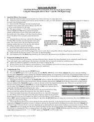
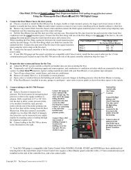
3.2 TrueFlow Measurement Procedure Using the DG-700 Gauge<br />
Step 1: Measure the Normal System Operating Pressure (NSOP)<br />
• Turn on the air handler fan to the desired speed (typically using the thermostat).<br />
• Turn on the gauge and put it the PR/ AH mode by pressing the MODE button 4 times. <strong>The</strong> icon “NSOP” will<br />
begin to flash in the Channel A display. At this point, the gauge is monitoring the real-time Channel A NSOP<br />
pressure, but is not recording the reading. <strong>The</strong> Channel B display is not active at this time.<br />
• Press the START button to begin the NSOP measurement<br />
procedure on Channel A. Once the START button is<br />
pressed, the NSOP icon stops flashing and the gauge begins<br />
recording a long-term average NSOP pressure reading on<br />
Channel A. During the measurement procedure, the<br />
Channel B display is used as a timer to let the user know<br />
how long (in seconds) the NSOP measurement has been active. <strong>The</strong> longer the measurement time, generally the<br />
more stable the reading typically becomes. In the screen to the right, the measured NSOP pressure is 56.7<br />
Pascals (measured over the past 30 seconds).<br />
• Once you are satisfied with the NSOP reading, press the ENTER key to accept and enter the reading into the<br />
gauge. Turn off the air handler fan, and leave the static pressure probe in place and connected to the gauge on<br />
Channel A.<br />
• Note: If the NSOP reading is very low (less than 10 Pascals), or the reading is fluctuating significantly, try to<br />
find a different location for the static pressure probe (see Appendix D).<br />
Step 2: Install the Metering Plate<br />
• Remove the existing filter and install the appropriate Metering Plate in place of the filter as described in<br />
Chapter 2. Note: If the Metering Plate is to be installed in a location that is different from the existing filter<br />
(e.g. installing the Metering Plate in a filter slot built into the air handler blower compartment, while the<br />
existing filter is located at a single return filter grille), the existing filter should still be removed.<br />
• Connect the tubing from the installed Metering Plate to the DG-700. Connect the Red ("total pressure grid")<br />
tubing connection to the Channel B Input pressure tap. Connect the Green ("static pressure grid") tubing<br />
connection to the Channel B Reference pressure tap.<br />
12 <strong>The</strong> ENERGY<br />
CONSERVATORY<br />
DIAGNOSTIC TOOLS TO MEASURE BUILDING PERFORMANCE