TrueFlow® User Manual - The Energy Conservatory
TrueFlow® User Manual - The Energy Conservatory
TrueFlow® User Manual - The Energy Conservatory

You also want an ePaper? Increase the reach of your titles
YUMPU automatically turns print PDFs into web optimized ePapers that Google loves.
Chapter 3<br />
TrueFlow Meter Test Procedure<br />
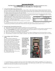
• Using Your Own Pressure Gauge:<br />
Adjust your pressure gauge to read zero if it has a manual zero adjustment. Now connect tubing to the gauge using<br />
the following scheme:<br />
- Connect the Red tubing connection to the positive (or high) pressure tap on your gauge.<br />
- Connect the Green tubing to the negative (or low) pressure tap on your gauge.<br />
Step 5: Measure and Record the Air Flow Through the Installed Metering Plate<br />
With the air handler fan continuing to run, measure and record the air flow through the Metering Plate.<br />
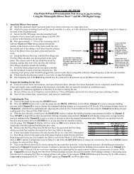
• Direct Flow Readings from the DG-3 Gauge<br />
In order for the DG-3 gauge to directly display air flow in CFM from the Metering Plate, the installed Metering<br />
Plate must be selected in the gauge.<br />
To select the Metering Plate being used in your test, first turn the MODE knob to the Fan Select position. <strong>The</strong><br />
gauge display will show "-SEL" to indicate that a flow measurement device has not yet been selected. <strong>The</strong> selected<br />
flow measurement device is chosen by toggling the SELECT Switch up.<br />
If the<br />
Display<br />
Shows<br />
-SEL<br />
PL 14<br />
PL 20<br />
Description<br />
Begin flow measurement device selection by toggling the SELECT switch up:<br />
- up 3 times to select the #14 Metering Plate.<br />
- up 4 times to select the #20 Metering Plate.<br />
This indicates that you have chosen the #14 TrueFlow Metering Plate.<br />
This indicates that you have chosen the #20 TrueFlow Metering Plate.<br />
Once the proper plate has been selected, turn the MODE switch to Flow. With the CHANNEL knob set to<br />
B, the gauge will now display the air flow through the Metering Plate in CFM. You may want to use the 5<br />
second, 10 second or Long-Term average setting if the flow reading is fluctuating.<br />
Note: DG-3 gauges sold prior to April 2001 may not have the PL14 or PL20 options when selecting a flow<br />
measurement device. <strong>The</strong>se gauges can be retrofitted with a new EPROM by <strong>The</strong> <strong>Energy</strong> <strong>Conservatory</strong><br />
(call for more information).<br />
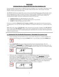
• Determining Air Flow Using the Flow Conversion Tables (DG-2, Magnehelic or other pressure gauges)<br />
Measure the pressure signal from the TrueFlow Metering Plate. If using the DG-2, this measurement is made on<br />
Channel B (you may want to use the 5 second, 10 second or Long-Term time-average setting if the reading is<br />
fluctuating.). <strong>The</strong> Metering Plate pressure can then be converted to airflow in CFM using the appropriate flow<br />
conversion table contained in Appendix A. Laminated flow conversion tables are also provided with the TrueFlow<br />
<strong>Manual</strong>.<br />
Step 6: Calculate a Flow Resistance Correction Factor<br />
A Flow Resistance Correction Factor can be determined using the two system operating pressure measurements<br />
made during the test procedure (Steps 1 and 3). <strong>The</strong> Flow Resistance Correction Factor is used to adjust the<br />
measured air flow through the Metering Plate for differences in resistance between the existing filter and the<br />
TrueFlow Meter.<br />
16 <strong>The</strong> ENERGY<br />
CONSERVATORY<br />
DIAGNOSTIC TOOLS TO MEASURE BUILDING PERFORMANCE