TrueFlow® User Manual - The Energy Conservatory
TrueFlow® User Manual - The Energy Conservatory
TrueFlow® User Manual - The Energy Conservatory

Create successful ePaper yourself
Turn your PDF publications into a flip-book with our unique Google optimized e-Paper software.
Appendix E<br />
Quick Guides<br />
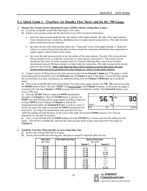
E.2 Quick Guide 2 – TrueFlow Air Handler Flow Meter and the DG-700 Gauge<br />
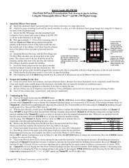
1. Measure the Normal System Operating Pressure (NSOP) with the existing filter in place.<br />
a) Locate the air handler system filter and replace if it is dirty.<br />
b) Install a static pressure probe into the ductwork at one of the 3 locations listed below:<br />
• Insert the static pressure probe into the side surface of the supply plenum. <strong>The</strong> side of the supply plenum<br />
chosen should not have a trunk line, distribution duct or supply register connected to it. <strong>The</strong> static pressure<br />
probe should point into the airstream.<br />
• Or, insert the tip of the static pressure probe into a "dead-end" corner of the supply plenum. A "dead-end"<br />
corner is a corner of the plenum that does not have a trunk line connection, distribution duct connection or<br />
supply register within 8 inches of the corner.<br />
• Or, insert the static pressure probe in the side surface of the return plenum. <strong>The</strong> side of the return plenum<br />
chosen should not have a trunk line, return duct or return register connected to it. <strong>The</strong> location chosen<br />
should also be at least 24 inches upstream from the TrueFlow Metering Plate, and at least 24 inches<br />
downstream from any 90 degree corners or return trunk line connections. <strong>The</strong> static pressure probe should<br />
point into the airstream. Note: if the Metering Plate will be installed at a remote filter grille, the static<br />
pressure probe may not be installed in the return plenum (i.e. install it in the supply plenum).<br />
c) Connect a piece of tubing between the static pressure probe and the Channel A Input tap. If the gauge is in the<br />
house during the test procedure, leave the Reference tap on Channel A open. If the gauge is not in the house during<br />
the test procedure (e.g. attic, crawlspace), run additional tubing from the Channel A Reference tap to inside the<br />
house.<br />
d) Turn on the air handler fan to the desired speed. Now turn on the gauge and put it the PR/ AH mode by pressing<br />
the MODE button 4 times. <strong>The</strong> icon “NSOP” will begin to flash in the Channel A display. At this point, the gauge is<br />
monitoring the real-time Channel A NSOP pressure, but is not recording the reading. <strong>The</strong> Channel B display is not<br />
active at this time.<br />
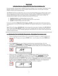
e) Press the START button to begin the NSOP measurement<br />
procedure on Channel A. Once the START button is pressed, the<br />
NSOP icon stops flashing and the gauge begins recording a long term<br />
average NSOP pressure reading on Channel A. During the<br />
measurement procedure, the Channel B display is used as a timer to<br />
let the user know how long (in seconds) the NSOP measurement has<br />
been active. <strong>The</strong> longer the measurement time, generally the more<br />
stable the reading typically becomes. In the screen to the right, the measured NSOP pressure is 56.7 Pascals<br />
(measured over the past 30 seconds).<br />
f) Once you are satisfied with the NSOP reading, press the ENTER key to accept and enter the reading into the<br />
gauge. Turn off the air handler fan, and leave the static pressure probe in place and connected to the gauge on<br />
Channel A.<br />
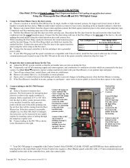
2. Install the TrueFlow Metering Plate in an Existing Filter Slot.<br />
a) Remove the existing filter and set it aside.<br />
b) Choose and assemble the metering plate and spacers needed to match the filter slot size.<br />
Filter Slot<br />
(in. x in.)<br />
Flow Metering Plate<br />
Spacer Dimension<br />
(in. x in.)<br />
Spacer 1 Spacer 2<br />
14 x 20 #14 ------ ------<br />
14 x 25 #14 5 x 14 ------<br />
16 x 20 #14 2 x 20 ------<br />
16 x 24 #14 2 x 20 4 x 16<br />
16 x 25 #14 2 x 20 5 x16<br />
18 x 20 #14 4 x 20 ------<br />
20 x 20 #20 ------ ------<br />
20 x 22 #20 2 x 20 ------<br />
20 x 24 #20 4 x 20 ------<br />
20 x 25 #20 5 x 20 ------<br />
20 x 30 #20 10 x 20 ------<br />
24 x 24 #20 4 x 20 4 x 24<br />
28 <strong>The</strong> ENERGY<br />
CONSERVATORY<br />
DIAGNOSTIC TOOLS TO MEASURE BUILDING PERFORMANCE