TrueFlow® User Manual - The Energy Conservatory
TrueFlow® User Manual - The Energy Conservatory
TrueFlow® User Manual - The Energy Conservatory

You also want an ePaper? Increase the reach of your titles
YUMPU automatically turns print PDFs into web optimized ePapers that Google loves.
TrueFlow ®<br />
Air Handler Flow Meter<br />
Operation <strong>Manual</strong><br />
<strong>The</strong> ENERGY<br />
CONSERVATORY<br />
DIAGNOSTIC TOOLS TO MEASURE BUILDING PERFORMANCE
TrueFlow ®<br />
Air Handler Flow Meter<br />
Operation <strong>Manual</strong><br />
<strong>The</strong> <strong>Energy</strong> <strong>Conservatory</strong><br />
2801 21st Ave. S., Suite 160<br />
Minneapolis, MN 55407<br />
612-827-1117 Fax 612-827-1051<br />
www.energyconservatory.com<br />
email: info@energyconservatory.com<br />
TrueFlow and Duct Blaster are registered trademarks of <strong>The</strong> <strong>Energy</strong> <strong>Conservatory</strong>, Inc.<br />
Magnehelic is a registered trademark of Dwyer Instruments, Inc.
<strong>Manual</strong> Edition: January 2006<br />
Copyright 2006. <strong>The</strong> <strong>Energy</strong> <strong>Conservatory</strong>, Inc. All rights reserved.<br />
EXPRESS LIMITED WARRANTY:<br />
ENERGY CONSERVATORY WARRANTY<br />
Seller warrants that this product, under normal use and service as described in the operator’s manual, shall be free from defects in workmanship<br />
and material for a period of 24 months, or such shorter length of time as may be specified in the operator’s manual, from the date of shipment to<br />
the Customer.<br />
LIMITATION OF WARRANTY AND LIABILITY:<br />
This limited warranty set forth above is subject to the following exclusions:<br />
a) With respect to any repair services rendered, Seller warrants that the parts repaired or replaced will be free from defects in<br />
workmanship and material, under normal use, for a period of 90 days from the date of shipment to the Purchaser.<br />
b) Seller does not provide any warranty on finished goods manufactured by others. Only the original manufacturer’s warranty applies.<br />
c) Unless specifically authorized in a separate writing, Seller makes no warranty with respect to, and shall have no liability in<br />
connection with, any goods which are incorporated into other products or equipment by the Purchaser.<br />
d) All products returned under warranty shall be at the Purchaser’s risk of loss. <strong>The</strong> Purchaser is responsible for all shipping charges to<br />
return the product to <strong>The</strong> <strong>Energy</strong> <strong>Conservatory</strong>. <strong>The</strong> <strong>Energy</strong> <strong>Conservatory</strong> will be responsible for return standard ground shipping<br />
charges. <strong>The</strong> Customer may request and pay for the added cost of expedited return shipping.<br />
<strong>The</strong> foregoing warranty is in lieu of all other warranties and is subject to the conditions and limitations stated herein. No other express or implied<br />
warranty IS PROVIDED, AND THE SELLER DISCLAIMS ANY IMPLIED WARRANTY OF FITNESS for particular purpose or<br />
merchantability.<br />
<strong>The</strong> exclusive remedy of the purchaser FOR ANY BREACH OF WARRANTY shall be the return of the product to the factory or designated<br />
location for repair or replacement, or, at the option of <strong>The</strong> <strong>Energy</strong> <strong>Conservatory</strong>, refund of the purchase price.<br />
<strong>The</strong> <strong>Energy</strong> <strong>Conservatory</strong>’s maximum liability for any and all losses, injuries or damages (regardless of whether such claims are based on<br />
contract, negligence, strict liability or other tort) shall be the purchase price paid for the products. In no event shall the Seller be liable for any<br />
special, incidental or consequential damages. <strong>The</strong> <strong>Energy</strong> <strong>Conservatory</strong> shall not be responsible for installation, dismantling, reassembly or<br />
reinstallation costs or charges. No action, regardless of form, may be brought against the Seller more than one year after the cause of action has<br />
accrued.<br />
<strong>The</strong> Customer is deemed to have accepted the terms of this Limitation of Warranty and Liability, which contains the complete and exclusive<br />
limited warranty of the Seller. This Limitation of Warranty and Liability may not be amended or modified, nor may any of its terms be waived<br />
except by a writing signed by an authorized representative of the Seller.<br />
TO ARRANGE A REPAIR: Please call <strong>The</strong> <strong>Energy</strong> <strong>Conservatory</strong> at 612-827-1117 before sending any product back for repair or to inquire<br />
about warranty coverage. All products returned for repair should include a return shipping address, name and phone number of a contact person<br />
concerning this repair, and the purchase date of the equipment.
Table of Contents<br />
Chapter 1 Introduction 1<br />
Chapter 2 System Components 2<br />
2.1 Metering Plates 2<br />
2.2 Spacers 3<br />
2.3 Installing the Metering Plates 5<br />
2.3.a Installing at a Filter Slot: 5<br />
2.3.b Installing at a Single Central Return: 6<br />
2.4 Static Pressure Probe 7<br />
2.5 Gauge Options 7<br />
2.5.a DG-700 Digital Pressure Gauge: 7<br />
2.5.b DG-2 and DG-3 Digital Pressure Gauges: 7<br />
2.5.c Magnehelic Gauges: 8<br />
Chapter 3 TrueFlow Meter Test Procedure 9<br />
3.1 Set-Up to Measure the Normal System Operating Pressure 10<br />
3.2 TrueFlow Measurement Procedure Using the DG-700 Gauge 12<br />
3.3 TrueFlow Measurement Procedure Using a DG-3, DG-2 or Other Gauge 14<br />
Appendix A Flow Conversion Tables 18<br />
Appendix B Flow Resistance Correction Factors 20<br />
Appendix C Calibration and Measurement Accuracy 22<br />
Appendix D System Pressure Measurement Location 24<br />
Appendix E Quick Guides 25<br />
Appendix F References 31
Chapter 1<br />
Introduction<br />
Chapter 1<br />
Introduction<br />
<strong>The</strong> air flow rate through residential air handlers is an important variable in estimating and optimizing the<br />
performance of heat pumps, air conditioners and furnaces. Numerous field studies of installed heating and cooling<br />
systems around the United States have found that insufficient air flow across the indoor coil is an extremely<br />
common problem. Low air flow can lead to decreased heating and cooling system capacity, increased energy use<br />
and comfort problems.<br />
<strong>The</strong> most widely used methods for estimating the air handler flow rate, (the temperature rise method, static pressure<br />
and fan curve method, and the Duct Blaster® isolated return method) have been found to be either problematic or<br />
time-consuming to perform. <strong>The</strong> <strong>Energy</strong> <strong>Conservatory</strong>’s TrueFlow® Air Handler Flow Meter is designed to provide<br />
a simple and accurate measurement of air flow through residential air handlers rated from 1 to 5 tons. <strong>The</strong> TrueFlow<br />
Meter temporarily replaces the filter in a typical air handler system during the airflow measurement procedure. If the<br />
filter location is directly adjacent to the air handler, the TrueFlow Meter will measure the total air handler flow. If<br />
the filter is located remotely at a single central return, the TrueFlow Meter will measure the airflow through the<br />
central return.<br />
Note: If the return duct system is very airtight, the air flow through the single central return will be very close to the<br />
total air handler flow.<br />
Extensive field testing of the TrueFlow Meter has shown that it:<br />
• Is easy and fast to use in the field. <strong>The</strong> TrueFlow Meter provides direct CFM readings in approximately 2 to 4<br />
minutes without extensive calculations or setup. <strong>The</strong> TrueFlow Meter requires about the same time as the<br />
single-point temperature rise method, when including the time required in the temperature method to measure<br />
the output capacity.<br />
• Can be used in a wide range of return plenums and air handler fan configurations. Adjustable sizing of the<br />
TrueFlow Meter allows it to fit most standard filter slots. Custom adjustments for unusual filter sizes can be<br />
easily made by the operator.<br />
• Has a flow accuracy of +/ 7% for most applications when used with a pressure gauge having an accuracy of 1%<br />
of reading. <strong>The</strong> TrueFlow Meter is approximately 4 times more accurate than the single-point temperature rise<br />
method, and of comparable accuracy to the Duct Blaster isolated return method.<br />
• Is applicable to many systems for which the temperature rise method cannot be used due to inadequate or absent<br />
supply plenum temperature measurement points.<br />
• Can be used with any manometer which has a resolution of 1 Pascal or 0.005 In H 2 O.<br />
1 <strong>The</strong> ENERGY<br />
CONSERVATORY<br />
DIAGNOSTIC TOOLS TO MEASURE BUILDING PERFORMANCE
Chapter 2<br />
System Components<br />
Chapter 2<br />
System Components<br />
<strong>The</strong> TrueFlow Air Handler Flow Meter consists of the following components:<br />
• 2 calibrated Metering Plates.<br />
• 8 spacers which attach to the Metering Plates to provide<br />
for sizing adjustments.<br />
• 1 static pressure probe.<br />
• Flow conversion tables used to convert Metering Plate<br />
pressure measurements to flow in Cubic Feet per Minute.<br />
• 10 feet of blue tubing and 30 feet of clear tubing.<br />
• Operation manual.<br />
• Carrying case.<br />
2.1 Metering Plates<br />
<strong>The</strong> TrueFlow Meter includes 2 Metering Plates (#14 and #20),<br />
each comprised of a clear plastic plate with a series of round<br />
metering holes and black pressure sensing grids. Each plate has<br />
H-channel gasket attached to all 4 sides. <strong>The</strong> H-channel gasket<br />
provides a seal around the Metering Plate when it is installed in<br />
a filter slot, and also provides an attachment channel to attach<br />
spacers to the plate. Two Metering Plates are provided due to<br />
the large range of filter sizes possible in residential air handling<br />
systems.<br />
<strong>The</strong> Metering Plates are installed in place of the system air<br />
filter, which is always located in the return side of the duct<br />
system. <strong>The</strong> front side of the Metering Plate, as shown in<br />
Figure 1, should be facing "upstream" into the airflow (i.e.<br />
away from the air handler fan). <strong>The</strong> 2 tubing connections to the<br />
plate's pressure sensing grids are located on the front side of the plate.<br />
#20<br />
#14<br />
Figure 1: Front Side of Metering Plate (should face into air flow)<br />
Connections to<br />
Sensing Grids<br />
2 <strong>The</strong> ENERGY<br />
CONSERVATORY<br />
DIAGNOSTIC TOOLS TO MEASURE BUILDING PERFORMANCE
Chapter 2<br />
System Components<br />
<strong>The</strong> rear side of the Metering Plate, as shown in Figure 2, should be facing "downstream" away from the air flow<br />
(i.e. toward the air handler fan). <strong>The</strong> plate's pressure sensing grids are attached to the rear side of the plate.<br />
Figure 2: Rear View of Metering Plate (should face away from air flow)<br />
Air flow through the Metering Plate is determined by measuring the pressure difference between the two sensing<br />
grids on the plate. <strong>The</strong> measured pressure difference is converted to air flow in Cubic Feet per Minute using a flow<br />
conversion table (see Appendix A). Each metering plate contains two tubing connections to the pressure sensing<br />
grids. <strong>The</strong> Red tubing connection provides a pressure signal from the plate's "total pressure" grid. <strong>The</strong> Green tubing<br />
connection provides a pressure signal from the plate's "static pressure" grid.<br />
2.2 Spacers<br />
<strong>The</strong> TrueFlow Meter comes with 8 spacers which are used to adjust the size of the Metering Plates. <strong>The</strong> 2 Metering<br />
Plates and 8 spacers are compatible with the following 12 standard filter sizes :<br />
Table 1: Standard Filter Sizes Compatible with the TrueFlow Meter<br />
Plate #14: 14 x 20 14 x 25 16 x 20 16 x 24 16 x 25 18 x20<br />
Plate #20: 20 x 20 20 x 22 20 x 24 20 x 25 20 x 30 24 x 24<br />
Each spacer consists of a clear plastic plate with H-channel gasket<br />
attached to three sides. Spacers are attached to the Metering Plate<br />
by pushing the open side of the spacer into the attachment channel<br />
found on the Metering Plate H-channel. Install the spacer so that<br />
the outside edge of the gasket on the spacer and the Metering Plate<br />
line up with each other.<br />
3 <strong>The</strong> ENERGY<br />
CONSERVATORY<br />
DIAGNOSTIC TOOLS TO MEASURE BUILDING PERFORMANCE
Chapter 2<br />
System Components<br />
It is sometimes necessary to attach two spacers to a Metering Plate<br />
at the same time. Attaching the second spacer is done in the same<br />
manner as the first spacer - push the open side of the second spacer<br />
into the attachment channels found on the Metering Plate and first<br />
spacer. Install the second spacer so that the outside edge of the<br />
gasket on the spacer and the Metering Plate line up with each other.<br />
Table 2 below lists the combination of Metering Plates and spacers needed to adjust the TrueFlow Meter to the 12<br />
most commonly found filter sizes.<br />
Table 2: Metering Plate and Spacer Selection Guide<br />
Filter Size<br />
(in. x in.)<br />
Flow Metering<br />
Plate<br />
Spacer Dimension<br />
(in. x In.)<br />
Spacer 1 Spacer 2<br />
14 x 20 #14 ------ ------<br />
14 x 25 #14 5 x 14 ------<br />
16 x 20 #14 2 x 20 ------<br />
16 x 24 #14 2 x 20 4 x 16<br />
16 x 25 #14 2 x 20 5 x16<br />
18 x 20 #14 4 x 20 ------<br />
20 x 20 #20 ------ ------<br />
20 x 22 #20 2 x 20 ------<br />
20 x 24 #20 4 x 20 ------<br />
20 x 25 #20 5 x 20 ------<br />
20 x 30 #20 10 x 20 ------<br />
24 x 24 #20 4 x 20 4 x 24<br />
To use the Selection Guide, locate the filter slot size in the “Filter Slot” column. Determine the TrueFlow Metering<br />
Plate and spacers needed by referring to the “Flow Metering Plate” and “Spacer Dimension” columns. For example,<br />
a 16” x 25” filter slot requires the #14 Metering Plate, along with the 2” x 20” and 5” x 16” spacers.<br />
Note: If you need to match a filter slot size that is not listed in the Selection Guide, custom sized spacers can be cut<br />
from any 3/32” or 1/8” thick material (e.g. plastic sheet or cardboard). <strong>The</strong>se custom spacers can be attached to the<br />
Metering Plates in the same manner as the standard spacers, or they can be taped to the edge of the Metering Plate.<br />
In addition, the H-channel gasket can be temporarily removed (by removing the gasket fastener plugs) to reduce the<br />
size of the Metering Plates or spacers.<br />
4 <strong>The</strong> ENERGY<br />
CONSERVATORY<br />
DIAGNOSTIC TOOLS TO MEASURE BUILDING PERFORMANCE
Chapter 2<br />
System Components<br />
2.3 Installing the Metering Plates<br />
2.3.a Installing at a Filter Slot:<br />
Remove the existing filter and slide the TrueFlow Metering Plate completely into the empty filter slot. Install the<br />
Metering Plate so that the front side of the plate is facing into the air flow (front side has two diamond shaped labels<br />
on it). <strong>The</strong> H-channel gasket should provide a seal around the Metering Plate - all of the air flow should pass<br />
through the Metering Plate and not around the plate. Be sure that the ends of the flexible tubing connections attached<br />
to the pressure sensing grids remain outside of the filter slot (these will be connected to a pressure gauge).<br />
Occasionally, drilling holes into the ductwork may be required as a pathway for the ends of the flexible tubing. <strong>The</strong><br />
flexible tubing can be passed through one of the plate's metering holes if this helps in getting the tubing ends outside<br />
of the filter slot.<br />
Sliding the TrueFlow Metering Plates Into a Filter Slot<br />
If you wish to install the Metering Plate in a blower compartment and there is no filter slot built into the<br />
compartment, it is sometimes possible to temporarily tape the Metering Plate into the compartment for the test<br />
procedure. In this case, be sure that the tape is not blocking any of the metering holes in the plate.<br />
Close the filter access opening. If the flexible tubing connections are<br />
coming through the filter slot opening, be careful NOT to pinch-off the<br />
flexible tubing with the filter slot cover. Temporarily seal around the<br />
filter slot cover with masking tape to prevent air leakage and to direct<br />
all air flow through the Metering Plate.<br />
Flexible tubing connections<br />
5 <strong>The</strong> ENERGY<br />
CONSERVATORY<br />
DIAGNOSTIC TOOLS TO MEASURE BUILDING PERFORMANCE
Chapter 2<br />
System Components<br />
Installation Notes<br />
- Obstructions within 6 inches upstream or 2 inches downstream of the Metering Plate that are blocking air flow<br />
through any of the metering holes may reduce the accuracy of the device.<br />
- If there is an obstruction, and there is a spacer attached to the Metering Plate, try to install the Metering Plate so<br />
that the spacer is directly in front of the obstruction (this will minimize the effect of the obstruction on the flow<br />
measurement).<br />
- If the Metering Plate is installed directly downstream of a 90 degree bend in the duct system, and there is a<br />
spacer attached to the plate, install the Metering Plate so that the spacer is on the inside corner of the bend (see<br />
Figure 3 below).<br />
Figure 3: Installing Spacer on Inside Corner of 90 Degree Bend<br />
Spacer<br />
2.3.b Installing at a Single Central Return:<br />
If you are installing the TrueFlow Metering Plate at the filter grille<br />
of a single return duct system, simply push the plate into the<br />
empty filter rack. Make sure that the front of the plate is facing out<br />
(into the air flow). <strong>The</strong> H-channel gasket should provide an<br />
airtight seal around the Metering Plate - all of the air flow should<br />
pass through the Metering Plate and not around the plate. Keep the<br />
filter grille door open during the remainder of the test.<br />
Note: If there are multiple returns in the duct system, the only way<br />
to use the TrueFlow Meter is to simultaneously install a TrueFlow<br />
Metering Plate at each of the returns.<br />
6 <strong>The</strong> ENERGY<br />
CONSERVATORY<br />
DIAGNOSTIC TOOLS TO MEASURE BUILDING PERFORMANCE
Chapter 2<br />
System Components<br />
2.4 Static Pressure Probe<br />
<strong>The</strong> TrueFlow Meter comes with one static pressure probe. During the<br />
air flow measurement procedure, the operator will need to measure the<br />
operating pressure in the duct system, both with the existing filter in<br />
place and with the TrueFlow Meter in place. <strong>The</strong>se two operating<br />
pressure measurements are used to adjust the measured air flow through<br />
the Metering Plate for differences in resistance between the existing<br />
filter and the TrueFlow Meter.<br />
2.5 Gauge Options<br />
To use the TrueFlow Meter, you will need a pressure gauge with a resolution of 1 Pascal (or 0.005 In. H 2 O). <strong>The</strong><br />
TrueFlow Meter can be purchased with any of <strong>The</strong> <strong>Energy</strong> <strong>Conservatory</strong>'s Digital Pressure Gauges (Models<br />
DG-700, DG-3 and DG-2), with a set of two Magnehelic® gauges (60 Pa and 250 Pa), or purchased alone for use<br />
with an existing pressure gauge.<br />
2.5.a DG-700 Digital Pressure Gauge:<br />
<strong>The</strong> DG-700’s two independent pressure sensors and built-in Air Handler Flow<br />
measurement mode make it extremely easy to directly measure and display air<br />
handler flow (in CFM) with the TrueFlow system. <strong>The</strong> DG-700 is shipped in a<br />
separate padded case and can be purchased with a gauge board that can be easily<br />
mounted on any metallic surface. <strong>The</strong> DG-700 gauge provides an air flow<br />
measurement accuracy of +/- 7% when used with the TrueFlow Metering Plates.<br />
DG-700<br />
2.5.b DG-2 and DG-3 Digital Pressure Gauges:<br />
<strong>The</strong> DG-2 and DG-3 pressure gauges each have a single<br />
pressure sensor with two switchable measurement channels<br />
which allows you to monitor both the operating pressure in<br />
the duct system, as well as the pressure signal from the<br />
TrueFlow Metering Plate. <strong>The</strong> DG-3 also has the capability<br />
to display the measured airflow through the TrueFlow<br />
Metering Plate directly in cubic feet per minute (CFM). <strong>The</strong><br />
digital gauges are shipped in a separate padded case and<br />
can be purchased with a gauge board that can be easily<br />
mounted on any metallic surface. Both the DG-3 and DG-2<br />
gauges provide an air flow measurement accuracy of<br />
+/- 7% when used with the TrueFlow Metering Plates.<br />
DG-3<br />
DG-2<br />
7 <strong>The</strong> ENERGY<br />
CONSERVATORY<br />
DIAGNOSTIC TOOLS TO MEASURE BUILDING PERFORMANCE
Chapter 2<br />
System Components<br />
2.5.c Magnehelic Gauges:<br />
<strong>The</strong> Magnehelic gauges come mounted on a gauge board that can be easily mounted on<br />
any metallic surface. Two gauges are provided (60 Pascal and 250 Pascal) to provide the<br />
necessary measurement accuracy over a wide range of pressures. When using the<br />
Magnehelic gauges, air flow measurement accuracy of the TrueFlow Meter is +/- 9%.<br />
8 <strong>The</strong> ENERGY<br />
CONSERVATORY<br />
DIAGNOSTIC TOOLS TO MEASURE BUILDING PERFORMANCE
Chapter 3<br />
TrueFlow Meter Test Procedure<br />
Chapter 3<br />
TrueFlow Meter Test Procedure<br />
In order to measure total air flow through the air handler, it is best to install the TrueFlow Metering Plate in a filter<br />
slot as close to the air handler blower as possible. Many duct systems have a filter slot built into the return plenum<br />
ductwork. In addition, most air handler cabinets have a filter slot built into the blower compartment directly<br />
upstream of the blower. Install the TrueFlow Metering Plate in these filter slot locations whenever possible.<br />
A TrueFlow Metering Plate can also be installed at the filter grille of a single return duct system. In this case, the<br />
TrueFlow Meter will be measuring the air flow through the single return. If the return duct system is very airtight,<br />
the air flow through the single return will be very close to the total system air flow. If the duct system has multiple<br />
returns, the only way to use the TrueFlow Meter is to simultaneously install a TrueFlow Metering Plate at each of<br />
the returns.<br />
Figure 4: Example Duct System<br />
Supply<br />
Air Handler Cabinet<br />
Blower<br />
Return<br />
Filter<br />
Grille<br />
Filter Slot<br />
Return<br />
<strong>The</strong> basic test procedure for using the TrueFlow Meter involves the following six steps (test procedure Quick<br />
Guides are located in Appendix E at the end of this manual):<br />
1. With the air handler "on" and the existing filter in place, measure the Normal System Operating Pressure (NSOP)<br />
using a static pressure probe.<br />
2. Replace the existing filter with one of the TrueFlow Metering Plates.<br />
3. Measure the system operating pressure with the TrueFlow Metering Plate in place (TrueFlow System Operating<br />
Pressure or TFSOP) using a static pressure probe.<br />
4. Measure the air flow through the TrueFlow Metering Plate using the pressure signal from the Metering Plate.<br />
5. Calculate a Flow Resistance Correction Factor using the 2 operating pressure measurements (Steps 1 & 3).<br />
6. Multiply the measured air flow through the Metering Plate by the Flow Resistance Correction Factor for the final<br />
adjusted air flow result.<br />
Note: <strong>The</strong> DG-700’s built-in Air Handler Flow Mode automatically calculates and applies the Flow Resistance<br />
Correction Factor (#5 & #6 above).<br />
9 <strong>The</strong> ENERGY<br />
CONSERVATORY<br />
DIAGNOSTIC TOOLS TO MEASURE BUILDING PERFORMANCE
Chapter 3<br />
TrueFlow Meter Test Procedure<br />
3.1 Set-Up to Measure the Normal System Operating Pressure<br />
a) Locate the air handler system filter and replace if dirty,<br />
Locate the air handling system filter and if it is dirty, replace with a new one. A dirty filter can significantly reduce<br />
air flow through the air handling system. Note: If you wish to measure the air flow with the dirty filter, leave the<br />
dirty filter in place.<br />
b) Open all registers and outside window.<br />
Make sure all supply and return registers are open. Open a window or door between the building and outside to<br />
prevent pressure changes in the building during the test. If the air handler fan is installed in an unconditioned zone<br />
(e.g. crawlspace, attic), open any vents or access doors connecting that zone to the outside (or to the building) to<br />
prevent pressure changes in the zone during the test.<br />
c) Install the static pressure probe.<br />
Install the static pressure probe into the ductwork at any one of the three locations listed below (the operator will<br />
typically need to drill or punch a small hole in the ductwork in order to insert the static pressure probe):<br />
• Insert the static pressure probe into the side surface of the supply<br />
plenum. <strong>The</strong> side of the supply plenum chosen should not have a<br />
trunk line, distribution duct or supply register connected to it. <strong>The</strong><br />
static pressure probe should point into the airstream.<br />
• Or, insert the tip of the static pressure probe into a "dead-end"<br />
corner of the supply plenum. A "dead-end" corner is simply a<br />
corner of the plenum that does not have a trunk line connection,<br />
distribution duct connection or supply register within 8 inches of<br />
the corner.<br />
• Or, insert the static pressure probe in the side surface of the return<br />
plenum. <strong>The</strong> side of the return plenum chosen should not have a<br />
trunk line, return duct or return register connected to it. <strong>The</strong> location chosen should also be at least 24 inches<br />
upstream from the TrueFlow Metering Plate, and at least 24 inches downstream from any 90 degree corners or<br />
return trunk line connections. <strong>The</strong> static pressure probe should point into the airstream. Note: If the Metering<br />
Plate will be installed at a remote filter grille, the static pressure probe may not be installed in the return plenum<br />
(i.e. install it in the supply plenum).<br />
<strong>The</strong>se three duct locations typically provide a very stable static pressure reading and are readily available in most<br />
applications. If one of the three locations listed above is not available, see Appendix D for other location options.<br />
d) Connect the static pressure probe to a pressure gauge.<br />
Static Pressure Probe<br />
Connect one end of the static pressure probe to the 10 foot length of blue tubing. Now connect the remaining end of<br />
the tubing to a pressure gauge. Note: If you are using the "dead-end" corner location, you may simply insert the end<br />
of the tubing into the "dead-end" corner and not use a static pressure probe.<br />
10 <strong>The</strong> ENERGY<br />
CONSERVATORY<br />
DIAGNOSTIC TOOLS TO MEASURE BUILDING PERFORMANCE
Chapter 3<br />
TrueFlow Meter Test Procedure<br />
• DG-700, DG-3 or DG-2 Pressure Gauge<br />
If using a DG-700, DG-3 or DG-2 digital pressure gauge, connect the end of the blue tubing to the Channel A Input<br />
pressure tap. If the pressure gauge is located inside the house, leave the Channel A Reference tap on the gauge<br />
open (we want to measure the system operating pressure with reference to the house). If the pressure gauge is not<br />
located in the house (e.g. it is in the crawlspace, garage, or attic), run the 30 foot piece of clear tubing from the<br />
Channel A Reference tap to inside the house<br />
Figure 5: Connecting the Static Pressure Probe to a DG-700, DG-3 or DG-2 Gauge<br />
Connect static pressure probe to<br />
the Channel A Input tap.<br />
If gauge is in the house, leave Reference tap open. If<br />
gauge is not in the house, run additional tubing from<br />
the Reference tap to inside the house.<br />
• Magnehelic Gauges<br />
If using the Magnehelic gauges, first mount the magnetic gauge board on a vertical metal surface (e.g. the air<br />
handler cabinet or supply plenum). Adjust both gauges to read zero. Magnehelic gauge adjustments are made by<br />
turning the adjustment screw near the bottom of the gauge with a small screwdriver while gently tapping the face<br />
plate of the gauge. Now connect the end of the blue tubing to the 60 Pascal gauge using the following scheme:<br />
- If the static pressure probe is inserted into the supply plenum,<br />
connect the blue tubing to the top tap on the 60 Pascal gauge.<br />
- If the static pressure probe is inserted into the return plenum,<br />
connect the blue tubing to the bottom tap on the 60 Pascal gauge.<br />
- If the pressure gauge is located inside the house, leave the remaining pressure tap<br />
on the gauge open. If the pressure gauge is not located in the house (e.g. it is in the<br />
crawlspace, garage, or attic), run the 30' piece of clear tubing from the remaining pressure<br />
tap to inside the house.<br />
11 <strong>The</strong> ENERGY<br />
CONSERVATORY<br />
DIAGNOSTIC TOOLS TO MEASURE BUILDING PERFORMANCE
Chapter 3<br />
TrueFlow Meter Test Procedure<br />
• Using Your Own Pressure Gauge<br />
Adjust your pressure gauge to read zero if it has a manual zero adjustment. Now connect the end of the blue tubing<br />
to your gauge using the following scheme:<br />
- If the static pressure probe is inserted into the supply plenum, connect the blue tubing to the positive (or<br />
high) pressure tap on your gauge.<br />
- If the static pressure probe is inserted into the return plenum, connect the blue tubing to the negative (or<br />
low) pressure tap on your gauge.<br />
- If the pressure gauge is located inside the house, leave the remaining pressure tap on the gauge open. If the<br />
pressure gauge is not located in the house (e.g. it is in the crawlspace, garage, or attic), run the 30' piece of<br />
clear tubing from the remaining pressure tap to inside the house.<br />
3.2 TrueFlow Measurement Procedure Using the DG-700 Gauge<br />
Step 1: Measure the Normal System Operating Pressure (NSOP)<br />
• Turn on the air handler fan to the desired speed (typically using the thermostat).<br />
• Turn on the gauge and put it the PR/ AH mode by pressing the MODE button 4 times. <strong>The</strong> icon “NSOP” will<br />
begin to flash in the Channel A display. At this point, the gauge is monitoring the real-time Channel A NSOP<br />
pressure, but is not recording the reading. <strong>The</strong> Channel B display is not active at this time.<br />
• Press the START button to begin the NSOP measurement<br />
procedure on Channel A. Once the START button is<br />
pressed, the NSOP icon stops flashing and the gauge begins<br />
recording a long-term average NSOP pressure reading on<br />
Channel A. During the measurement procedure, the<br />
Channel B display is used as a timer to let the user know<br />
how long (in seconds) the NSOP measurement has been active. <strong>The</strong> longer the measurement time, generally the<br />
more stable the reading typically becomes. In the screen to the right, the measured NSOP pressure is 56.7<br />
Pascals (measured over the past 30 seconds).<br />
• Once you are satisfied with the NSOP reading, press the ENTER key to accept and enter the reading into the<br />
gauge. Turn off the air handler fan, and leave the static pressure probe in place and connected to the gauge on<br />
Channel A.<br />
• Note: If the NSOP reading is very low (less than 10 Pascals), or the reading is fluctuating significantly, try to<br />
find a different location for the static pressure probe (see Appendix D).<br />
Step 2: Install the Metering Plate<br />
• Remove the existing filter and install the appropriate Metering Plate in place of the filter as described in<br />
Chapter 2. Note: If the Metering Plate is to be installed in a location that is different from the existing filter<br />
(e.g. installing the Metering Plate in a filter slot built into the air handler blower compartment, while the<br />
existing filter is located at a single return filter grille), the existing filter should still be removed.<br />
• Connect the tubing from the installed Metering Plate to the DG-700. Connect the Red ("total pressure grid")<br />
tubing connection to the Channel B Input pressure tap. Connect the Green ("static pressure grid") tubing<br />
connection to the Channel B Reference pressure tap.<br />
12 <strong>The</strong> ENERGY<br />
CONSERVATORY<br />
DIAGNOSTIC TOOLS TO MEASURE BUILDING PERFORMANCE
Chapter 3<br />
TrueFlow Meter Test Procedure<br />
Figure 6: Connecting the Metering Plate to the DG-700<br />
Channel A Input tap should<br />
remain connected to the<br />
static pressure probe.<br />
Connect Red tubing to the<br />
Channel B Input tap<br />
Connect the Green tubing to the<br />
Channel B Reference tap..<br />
Note: With the DG-700 don’t worry if you reverse the Red and Green tubing connections because the absolute<br />
pressure difference between the tubing connections is used to determine air flow.<br />
Step 3: Measure the TrueFlow System Operating Pressure (TFSOP) and Adjusted Total Air Handler Flow<br />
• Check and adjust if necessary the selected test Device and Configuration shown in the upper part of the gauge<br />
display to match the Metering Plate installed in Step 2 above. When using the TrueFlow Metering Plates, the<br />
Device icon should always be set to TF, and the Configuration icon should be set to 14 or 20 depending on<br />
which Metering Plate is installed. Changes to the selected Device and Configuration are made by pressing the<br />
DEVICE and CONFIG buttons.<br />
• Turn the air handler fan back on to the same speed as used<br />
in Step 1 above. Channel A will now display the TFSOP<br />
reading from the static pressure probe, and Channel B will<br />
display adjusted air handler flow. <strong>The</strong> static pressure probe<br />
should be in exactly the same position as it was in Step 1<br />
above. <strong>The</strong> air handler flow rate estimate shown on<br />
Channel B is determined by continuously adjusting the measured air flow from the TrueFlow Metering Plate<br />
using a flow resistance correction factor calculated from the NSOP and TFSOP pressure readings. If the<br />
readings are fluctuating, change the time averaging setting to 5 second, 10 second, or Long-Term average using<br />
the TIME AVG button.<br />
• Record the adjusted air flow reading from Channel B. This result is the estimated air flow at the measurement<br />
location with the existing filter in place. Turn off the air handler fan.<br />
Note: When the TrueFlow Air Handler Flow Meter is installed at a remote filter grille, it is possible to make a<br />
correction to the measured flow through the Metering Plate which increases the accuracy of the flow measurement.<br />
See Appendix C for more details.<br />
13 <strong>The</strong> ENERGY<br />
CONSERVATORY<br />
DIAGNOSTIC TOOLS TO MEASURE BUILDING PERFORMANCE
Chapter 3<br />
TrueFlow Meter Test Procedure<br />
3.3 TrueFlow Measurement Procedure Using a DG-3, DG-2 or Other Gauge<br />
Step 1: Measure the Normal System Operating Pressure (NSOP)<br />
• Turn on the air handler fan to the desired speed (typically using the thermostat).<br />
• If using a DG-3 or DG-2 gauge, set-up the gauge to measure pressure on Channel A and turn the RANGE<br />
switch to Low (200.0). You may want to use the 5 second, 10 second or Long-Term time-average setting if the<br />
pressure reading is fluctuating.<br />
• Measure and record the NSOP reading from the static pressure probe. Turn off the air handler fan, and leave the<br />
static pressure probe in place and connected to the gauge.<br />
• If the NSOP reading is very low (less than 10 Pascals), or the reading is fluctuating significantly, try to find a<br />
different location for the static pressure probe (see Appendix D).<br />
• When using the Magnehelic gauges and the NSOP reading is greater than 60 Pascals, switch the tubing<br />
connection(s) from the 60 Pascal gauge to the 250 Pascal gauge and record the reading.<br />
Step 2: Install the Metering Plate<br />
• Remove the existing filter and install the appropriate Metering Plate in place of the filter as described in<br />
Chapter 2. Note: If the Metering Plate is to be installed in a location that is different from the existing filter<br />
(e.g. installing the Metering Plate in a filter slot built into the air handler blower compartment, while the<br />
existing filter is located at a single return filter grille), the existing filter should still be removed.<br />
Step 3: Measure the TrueFlow System Operating Pressure (TFSOP)<br />
• Turn the air handler fan back on to the same speed as used in Step 1 above.<br />
• Measure and record the TrueFlow system operating pressure (TFSOP) using the static pressure probe. <strong>The</strong><br />
static pressure probe should be in exactly the same position as it was in Step 1 above.<br />
• If using a DG-3 or DG-2 gauge, this measurement is made on Channel A. You may want to use the 5 second,<br />
10 second or Long-Term time-average setting if the pressure reading is fluctuating.<br />
• If using Magnehelic gauges and the TFSOP reading is greater than 60 Pascals, switch the tubing connection(s)<br />
from the 60 Pascal gauge to the 250 Pascal gauge and record the reading.<br />
Step 4: Connect the Tubing from the Installed Metering Plate to your Pressure Gauge<br />
• DG-3 or DG-2 Pressure Gauge:<br />
Connect the Red ("total pressure grid") tubing connection to the Channel B Input pressure tap. Connect the Green<br />
("static pressure grid") tubing connection to the Channel B Reference pressure tap.<br />
14 <strong>The</strong> ENERGY<br />
CONSERVATORY<br />
DIAGNOSTIC TOOLS TO MEASURE BUILDING PERFORMANCE
Chapter 3<br />
TrueFlow Meter Test Procedure<br />
Figure 7: Connecting the Metering Plate to the DG-3 and DG-2 Gauges<br />
Connect Red tubing to the<br />
Channel B Input tap.<br />
Connect the Green tubing to the<br />
Channel B Reference tap.<br />
Note: With the DG-3 or DG-2 gauges, don’t worry if you reverse the Red and Green tubing connections because the<br />
absolute pressure difference between the tubing connections is used to determine air flow.<br />
• Magnehelic Gauges:<br />
First disconnect the tubing used to measure the NSOP and TFSOP readings. Now re-zero the Magnehelic gauges by<br />
turning the adjustment screw near the bottom of the gauges with a small screwdriver while gently tapping the<br />
faceplate. Connect the Red ("total pressure grid") tubing connection to the top tap on the 60 Pascal gauge. Connect<br />
the Green ("static pressure grid") tubing connection to the bottom tap on the 60 Pascal gauge.<br />
Figure 8: Connecting the Metering Plate to Magnehelic Gauges<br />
Connect the Red tubing to the top tap<br />
on the 60 Pascal gauge.<br />
Connect the Green tubing to the bottom<br />
tap on the 60 Pascal gauge.<br />
15 <strong>The</strong> ENERGY<br />
CONSERVATORY<br />
DIAGNOSTIC TOOLS TO MEASURE BUILDING PERFORMANCE
Chapter 3<br />
TrueFlow Meter Test Procedure<br />
• Using Your Own Pressure Gauge:<br />
Adjust your pressure gauge to read zero if it has a manual zero adjustment. Now connect tubing to the gauge using<br />
the following scheme:<br />
- Connect the Red tubing connection to the positive (or high) pressure tap on your gauge.<br />
- Connect the Green tubing to the negative (or low) pressure tap on your gauge.<br />
Step 5: Measure and Record the Air Flow Through the Installed Metering Plate<br />
With the air handler fan continuing to run, measure and record the air flow through the Metering Plate.<br />
• Direct Flow Readings from the DG-3 Gauge<br />
In order for the DG-3 gauge to directly display air flow in CFM from the Metering Plate, the installed Metering<br />
Plate must be selected in the gauge.<br />
To select the Metering Plate being used in your test, first turn the MODE knob to the Fan Select position. <strong>The</strong><br />
gauge display will show "-SEL" to indicate that a flow measurement device has not yet been selected. <strong>The</strong> selected<br />
flow measurement device is chosen by toggling the SELECT Switch up.<br />
If the<br />
Display<br />
Shows<br />
-SEL<br />
PL 14<br />
PL 20<br />
Description<br />
Begin flow measurement device selection by toggling the SELECT switch up:<br />
- up 3 times to select the #14 Metering Plate.<br />
- up 4 times to select the #20 Metering Plate.<br />
This indicates that you have chosen the #14 TrueFlow Metering Plate.<br />
This indicates that you have chosen the #20 TrueFlow Metering Plate.<br />
Once the proper plate has been selected, turn the MODE switch to Flow. With the CHANNEL knob set to<br />
B, the gauge will now display the air flow through the Metering Plate in CFM. You may want to use the 5<br />
second, 10 second or Long-Term average setting if the flow reading is fluctuating.<br />
Note: DG-3 gauges sold prior to April 2001 may not have the PL14 or PL20 options when selecting a flow<br />
measurement device. <strong>The</strong>se gauges can be retrofitted with a new EPROM by <strong>The</strong> <strong>Energy</strong> <strong>Conservatory</strong><br />
(call for more information).<br />
• Determining Air Flow Using the Flow Conversion Tables (DG-2, Magnehelic or other pressure gauges)<br />
Measure the pressure signal from the TrueFlow Metering Plate. If using the DG-2, this measurement is made on<br />
Channel B (you may want to use the 5 second, 10 second or Long-Term time-average setting if the reading is<br />
fluctuating.). <strong>The</strong> Metering Plate pressure can then be converted to airflow in CFM using the appropriate flow<br />
conversion table contained in Appendix A. Laminated flow conversion tables are also provided with the TrueFlow<br />
<strong>Manual</strong>.<br />
Step 6: Calculate a Flow Resistance Correction Factor<br />
A Flow Resistance Correction Factor can be determined using the two system operating pressure measurements<br />
made during the test procedure (Steps 1 and 3). <strong>The</strong> Flow Resistance Correction Factor is used to adjust the<br />
measured air flow through the Metering Plate for differences in resistance between the existing filter and the<br />
TrueFlow Meter.<br />
16 <strong>The</strong> ENERGY<br />
CONSERVATORY<br />
DIAGNOSTIC TOOLS TO MEASURE BUILDING PERFORMANCE
Chapter 3<br />
TrueFlow Meter Test Procedure<br />
A table of Flow Resistance Correction Factors can be found in Appendix B and are based on the following formula.<br />
• Flow Resistance Correction Factor = NSOP / TFSOP<br />
where:<br />
- NSOP equals the normal system operating pressure recorded from Step 1.<br />
- TFSOP equals the system operating pressure with the TrueFlow Metering Plate installed recorded<br />
from Step 3.<br />
Laminated correction factor tables are also provided with the TrueFlow <strong>Manual</strong>.<br />
Step 7: Calculate the Adjusted Air Flow<br />
Multiply the measured air flow through the TrueFlow Metering Plate (Step 5) by the Flow Resistance Correction<br />
Factor (Step 6) to determine the final adjusted air flow result. This result is the estimated air flow at the<br />
measurement location with the existing filter in place. Turn off the air handler fan.<br />
Example:<br />
Using the #20 Metering Plate, the three test readings are:<br />
Normal system operating pressure (NSOP) = 50 Pa<br />
TrueFlow system operating pressure (TFSOP) = 46 Pa<br />
Air Flow through the TrueFlow Metering Plate = 1,152 CFM (56 Pa Metering Plate pressure)<br />
From Appendix B, the Flow Resistance Correction Factor equals 1.04.<br />
<strong>The</strong> Adjusted Air Flow equals 1,198 CFM (1,152 CFM x 1.04)<br />
Note: When the TrueFlow Air Handler Flow Meter is installed at a remote filter grille, it is possible to make a<br />
correction to the measured flow through the Metering Plate which increases the accuracy of the flow measurement.<br />
See Appendix C for more details.<br />
17 <strong>The</strong> ENERGY<br />
CONSERVATORY<br />
DIAGNOSTIC TOOLS TO MEASURE BUILDING PERFORMANCE
Appendix A<br />
TrueFlow Meter Flow Conversion Tables<br />
Appendix A<br />
Flow Conversion Tables<br />
Table A.1: Flow Conversion Table for TrueFlow Metering Plates (using Pascals)<br />
Plate Plate Plate Plate Plate Plate Plate Plate Plate<br />
Pressure #14 #20 Pressure #14 #20 Pressure #14 #20<br />
(Pascals) (CFM) (CFM) 66 934 1251 126 1291 1729<br />
67 941 1261 127 1296 1735<br />
68 948 1270 128 1301 1742<br />
69 955 1279 129 1306 1749<br />
10 364 487 70 962 1288 130 1311 1756<br />
11 381 511 71 969 1298 131 1316 1763<br />
12 398 533 72 976 1307 132 1321 1769<br />
13 415 555 73 983 1316 133 1326 1776<br />
14 430 576 74 989 1325 134 1331 1783<br />
15 445 596 75 996 1334 135 1336 1789<br />
16 460 616 76 1003 1343 136 1341 1796<br />
17 474 635 77 1009 1351 137 1346 1803<br />
18 488 653 78 1016 1360 138 1351 1809<br />
19 501 671 79 1022 1369 139 1356 1816<br />
20 514 689 80 1029 1377 140 1361 1822<br />
21 527 706 81 1035 1386 141 1366 1829<br />
22 539 722 82 1041 1395 142 1370 1835<br />
23 552 739 83 1048 1403 143 1375 1842<br />
24 563 754 84 1054 1411 144 1380 1848<br />
25 575 770 85 1060 1420 145 1385 1854<br />
26 586 785 86 1066 1428 146 1390 1861<br />
27 598 800 87 1073 1436 147 1394 1867<br />
28 609 815 88 1079 1445 148 1399 1873<br />
29 619 829 89 1085 1453 149 1404 1880<br />
30 630 843 90 1091 1461 150 1408 1886<br />
31 640 857 91 1097 1469 151 1413 1892<br />
32 651 871 92 1103 1477 152 1418 1899<br />
33 661 885 93 1109 1485 153 1422 1905<br />
34 671 898 94 1115 1493 154 1427 1911<br />
35 680 911 95 1121 1501 155 1432 1917<br />
36 690 924 96 1127 1509 156 1436 1923<br />
37 700 937 97 1133 1517 157 1441 1930<br />
38 709 949 98 1138 1525 158 1446 1936<br />
39 718 962 99 1144 1532 159 1450 1942<br />
40 727 974 100 1150 1540 160 1455 1948<br />
41 736 986 101 1156 1548 161 1459 1954<br />
42 745 998 102 1161 1555 162 1464 1960<br />
43 754 1010 103 1167 1563 163 1468 1966<br />
44 763 1022 104 1173 1570 164 1473 1972<br />
45 771 1033 105 1178 1578 165 1477 1978<br />
46 780 1044 106 1184 1586 166 1482 1984<br />
47 788 1056 107 1190 1593 167 1486 1990<br />
48 797 1067 108 1195 1600 168 1491 1996<br />
49 805 1078 109 1201 1608 169 1495 2002<br />
50 813 1089 110 1206 1615 170 1499 2008<br />
51 821 1100 111 1212 1622 171 1504 2014<br />
52 829 1111 112 1217 1630 172 1508 2020<br />
53 837 1121 113 1222 1637 173 1513 2026<br />
54 845 1132 114 1228 1644 174 1517 2031<br />
55 853 1142 115 1233 1651 175 1521 2037<br />
56 861 1152 116 1239 1659 176 1526 2043<br />
57 868 1163 117 1244 1666 177 1530 2049<br />
58 876 1173 118 1249 1673 178 1534 2055<br />
59 883 1183 119 1255 1680 179 1539 2060<br />
60 891 1193 120 1260 1687 180 1543 2066<br />
61 898 1203 121 1265 1694 181 1547 2072<br />
62 906 1213 122 1270 1701 182 1551 2078<br />
63 913 1222 123 1275 1708 183 1556 2083<br />
64 920 1232 124 1281 1715 184 1560 2089<br />
65 927 1242 125 1286 1722 185 1564 2095<br />
18 <strong>The</strong> ENERGY<br />
CONSERVATORY<br />
DIAGNOSTIC TOOLS TO MEASURE BUILDING PERFORMANCE
Appendix A<br />
TrueFlow Meter Flow Conversion Tables<br />
Table A.2: Flow Conversion Table for TrueFlow Metering Plates (using In. H 2 O)<br />
Plate Plate Plate Plate Plate Plate Plate Plate Plate<br />
Pressure #14 #20 Pressure #14 #20 Pressure #14 #20<br />
(In. H 2 0) (CFM) (CFM) 0.280 959 1284 0.580 1380 1848<br />
0.285 967 1296 0.585 1386 1856<br />
0.290 976 1307 0.590 1392 1864<br />
0.295 984 1318 0.595 1398 1872<br />
0.040 362 485 0.300 993 1329 0.600 1404 1880<br />
0.045 384 515 0.305 1001 1340 0.605 1410 1888<br />
0.050 405 543 0.310 1009 1351 0.610 1415 1895<br />
0.055 425 569 0.315 1017 1362 0.615 1421 1903<br />
0.060 444 594 0.320 1025 1373 0.620 1427 1911<br />
0.065 462 619 0.325 1033 1384 0.625 1433 1919<br />
0.070 479 642 0.330 1041 1394 0.630 1438 1926<br />
0.075 496 665 0.335 1049 1405 0.635 1444 1934<br />
0.080 513 686 0.340 1057 1415 0.640 1450 1942<br />
0.085 528 708 0.345 1064 1425 0.645 1455 1949<br />
0.090 544 728 0.350 1072 1436 0.650 1461 1957<br />
0.095 559 748 0.355 1080 1446 0.655 1467 1964<br />
0.100 573 767 0.360 1087 1456 0.660 1472 1972<br />
0.105 587 786 0.365 1095 1466 0.665 1478 1979<br />
0.110 601 805 0.370 1102 1476 0.670 1483 1986<br />
0.115 615 823 0.375 1110 1486 0.675 1489 1994<br />
0.120 628 841 0.380 1117 1496 0.680 1494 2001<br />
0.125 641 858 0.385 1124 1506 0.685 1500 2009<br />
0.130 653 875 0.390 1132 1516 0.690 1505 2016<br />
0.135 666 892 0.395 1139 1525 0.695 1511 2023<br />
0.140 678 908 0.400 1146 1535 0.700 1516 2030<br />
0.145 690 924 0.405 1153 1544 0.705 1522 2038<br />
0.150 702 940 0.410 1160 1554 0.710 1527 2045<br />
0.155 713 955 0.415 1167 1563 0.715 1532 2052<br />
0.160 725 971 0.420 1174 1573 0.720 1538 2059<br />
0.165 736 986 0.425 1181 1582 0.725 1543 2066<br />
0.170 747 1001 0.430 1188 1591 0.730 1548 2074<br />
0.175 758 1015 0.435 1195 1601 0.735 1554 2081<br />
0.180 769 1030 0.440 1202 1610 0.740 1559 2088<br />
0.185 779 1044 0.445 1209 1619 0.745 1564 2095<br />
0.190 790 1058 0.450 1216 1628 0.750 1569 2102<br />
0.195 800 1072 0.455 1222 1637<br />
0.200 810 1085 0.460 1229 1646<br />
0.172 752 1007 0.465 1236 1655<br />
0.176 760 1018 0.470 1242 1664<br />
0.180 769 1030 0.475 1249 1673<br />
0.184 777 1041 0.480 1256 1681<br />
0.188 786 1052 0.485 1262 1690<br />
0.192 794 1063 0.490 1269 1699<br />
0.196 802 1074 0.495 1275 1707<br />
0.200 810 1085 0.500 1281 1716<br />
0.205 821 1099 0.505 1288 1725<br />
0.210 830 1112 0.510 1294 1733<br />
0.215 840 1125 0.515 1301 1742<br />
0.220 850 1138 0.520 1307 1750<br />
0.225 860 1151 0.525 1313 1758<br />
0.230 869 1164 0.530 1319 1767<br />
0.235 879 1176 0.535 1326 1775<br />
0.240 888 1189 0.540 1332 1783<br />
0.245 897 1201 0.545 1338 1792<br />
0.250 906 1213 0.550 1344 1800<br />
0.255 915 1226 0.555 1350 1808<br />
0.260 924 1237 0.560 1356 1816<br />
0.265 933 1249 0.565 1362 1824<br />
0.270 942 1261 0.570 1368 1832<br />
0.275 950 1273 0.575 1374 1840<br />
19 <strong>The</strong> ENERGY<br />
CONSERVATORY<br />
DIAGNOSTIC TOOLS TO MEASURE BUILDING PERFORMANCE
Appendix B<br />
Flow Resistance Correction Factors<br />
Appendix B<br />
Flow Resistance Correction Factors<br />
Table B.1: Flow Resistance Correction Factors (using Pascals)<br />
Normal System Operating Pressure in Pascals (NSOP)<br />
TrueFlow<br />
System<br />
Operating<br />
Pressure<br />
in<br />
Pascals.<br />
(TF SOP)<br />
10 12 14 16 18 20 22 24 26 28 30 32 34 36 38 40 42 44 46 48 50<br />
10 1.00 1.10 1.18 1.26 1.34 1.41 1.48 1.55 1.61 1.67 1.73 1.79 1.84 1.90 1.95 2.00 2.05 2.10 2.14 2.19 2.24<br />
12 0.91 1.00 1.08 1.15 1.22 1.29 1.35 1.41 1.47 1.53 1.58 1.63 1.68 1.73 1.78 1.83 1.87 1.91 1.96 2.00 2.04<br />
14 0.85 0.93 1.00 1.07 1.13 1.20 1.25 1.31 1.36 1.41 1.46 1.51 1.56 1.60 1.65 1.69 1.73 1.77 1.81 1.85 1.89<br />
16 0.79 0.87 0.94 1.00 1.06 1.12 1.17 1.22 1.27 1.32 1.37 1.41 1.46 1.50 1.54 1.58 1.62 1.66 1.70 1.73 1.77<br />
18 0.75 0.82 0.88 0.94 1.00 1.05 1.11 1.15 1.20 1.25 1.29 1.33 1.37 1.41 1.45 1.49 1.53 1.56 1.60 1.63 1.67<br />
20 0.71 0.77 0.84 0.89 0.95 1.00 1.05 1.10 1.14 1.18 1.22 1.26 1.30 1.34 1.38 1.41 1.45 1.48 1.52 1.55 1.58<br />
22 0.67 0.74 0.80 0.85 0.90 0.95 1.00 1.04 1.09 1.13 1.17 1.21 1.24 1.28 1.31 1.35 1.38 1.41 1.45 1.48 1.51<br />
24 0.65 0.71 0.76 0.82 0.87 0.91 0.96 1.00 1.04 1.08 1.12 1.15 1.19 1.22 1.26 1.29 1.32 1.35 1.38 1.41 1.44<br />
26 0.62 0.68 0.73 0.78 0.83 0.88 0.92 0.96 1.00 1.04 1.07 1.11 1.14 1.18 1.21 1.24 1.27 1.30 1.33 1.36 1.39<br />
28 0.60 0.65 0.71 0.76 0.80 0.85 0.89 0.93 0.96 1.00 1.04 1.07 1.10 1.13 1.16 1.20 1.22 1.25 1.28 1.31 1.34<br />
30 0.58 0.63 0.68 0.73 0.77 0.82 0.86 0.89 0.93 0.97 1.00 1.03 1.06 1.10 1.13 1.15 1.18 1.21 1.24 1.26 1.29<br />
32 0.56 0.61 0.66 0.71 0.75 0.79 0.83 0.87 0.90 0.94 0.97 1.00 1.03 1.06 1.09 1.12 1.15 1.17 1.20 1.22 1.25<br />
34 0.54 0.59 0.64 0.69 0.73 0.77 0.80 0.84 0.87 0.91 0.94 0.97 1.00 1.03 1.06 1.08 1.11 1.14 1.16 1.19 1.21<br />
36 0.53 0.58 0.62 0.67 0.71 0.75 0.78 0.82 0.85 0.88 0.91 0.94 0.97 1.00 1.03 1.05 1.08 1.11 1.13 1.15 1.18<br />
38 0.51 0.56 0.61 0.65 0.69 0.73 0.76 0.79 0.83 0.86 0.89 0.92 0.95 0.97 1.00 1.03 1.05 1.08 1.10 1.12 1.15<br />
40 0.50 0.55 0.59 0.63 0.67 0.71 0.74 0.77 0.81 0.84 0.87 0.89 0.92 0.95 0.97 1.00 1.02 1.05 1.07 1.10 1.12<br />
42 0.49 0.53 0.58 0.62 0.65 0.69 0.72 0.76 0.79 0.82 0.85 0.87 0.90 0.93 0.95 0.98 1.00 1.02 1.05 1.07 1.09<br />
44 0.48 0.52 0.56 0.60 0.64 0.67 0.71 0.74 0.77 0.80 0.83 0.85 0.88 0.90 0.93 0.95 0.98 1.00 1.02 1.04 1.07<br />
46 0.47 0.51 0.55 0.59 0.63 0.66 0.69 0.72 0.75 0.78 0.81 0.83 0.86 0.88 0.91 0.93 0.96 0.98 1.00 1.02 1.04<br />
48 0.46 0.50 0.54 0.58 0.61 0.65 0.68 0.71 0.74 0.76 0.79 0.82 0.84 0.87 0.89 0.91 0.94 0.96 0.98 1.00 1.02<br />
50 0.45 0.49 0.53 0.57 0.60 0.63 0.66 0.69 0.72 0.75 0.77 0.80 0.82 0.85 0.87 0.89 0.92 0.94 0.96 0.98 1.00<br />
Normal System Operating Pressure in Pascals (NSOP)<br />
TrueFlow<br />
System<br />
Operating<br />
Pressure<br />
in Pascals.<br />
(TF SOP)<br />
50 55 60 65 70 75 80 85 90 95 100 105 110 115 120 125 130 135 140 145 150<br />
50 1.00 1.05 1.10 1.14 1.18 1.22 1.26 1.30 1.34 1.38 1.41 1.45 1.48 1.52 1.55 1.58 1.61 1.64 1.67 1.70 1.73<br />
55 0.95 1.00 1.04 1.09 1.13 1.17 1.21 1.24 1.28 1.31 1.35 1.38 1.41 1.45 1.48 1.51 1.54 1.57 1.60 1.62 1.65<br />
60 0.91 0.96 1.00 1.04 1.08 1.12 1.15 1.19 1.22 1.26 1.29 1.32 1.35 1.38 1.41 1.44 1.47 1.50 1.53 1.55 1.58<br />
65 0.88 0.92 0.96 1.00 1.04 1.07 1.11 1.14 1.18 1.21 1.24 1.27 1.30 1.33 1.36 1.39 1.41 1.44 1.47 1.49 1.52<br />
70 0.85 0.89 0.93 0.96 1.00 1.04 1.07 1.10 1.13 1.16 1.20 1.22 1.25 1.28 1.31 1.34 1.36 1.39 1.41 1.44 1.46<br />
75 0.82 0.86 0.89 0.93 0.97 1.00 1.03 1.06 1.10 1.13 1.15 1.18 1.21 1.24 1.26 1.29 1.32 1.34 1.37 1.39 1.41<br />
80 0.79 0.83 0.87 0.90 0.94 0.97 1.00 1.03 1.06 1.09 1.12 1.15 1.17 1.20 1.22 1.25 1.27 1.30 1.32 1.35 1.37<br />
85 0.77 0.80 0.84 0.87 0.91 0.94 0.97 1.00 1.03 1.06 1.08 1.11 1.14 1.16 1.19 1.21 1.24 1.26 1.28 1.31 1.33<br />
90 0.75 0.78 0.82 0.85 0.88 0.91 0.94 0.97 1.00 1.03 1.05 1.08 1.11 1.13 1.15 1.18 1.20 1.22 1.25 1.27 1.29<br />
95 0.73 0.76 0.79 0.83 0.86 0.89 0.92 0.95 0.97 1.00 1.03 1.05 1.08 1.10 1.12 1.15 1.17 1.19 1.21 1.24 1.26<br />
100 0.71 0.74 0.77 0.81 0.84 0.87 0.89 0.92 0.95 0.97 1.00 1.02 1.05 1.07 1.10 1.12 1.14 1.16 1.18 1.20 1.22<br />
105 0.69 0.72 0.76 0.79 0.82 0.85 0.87 0.90 0.93 0.95 0.98 1.00 1.02 1.05 1.07 1.09 1.11 1.13 1.15 1.18 1.20<br />
110 0.67 0.71 0.74 0.77 0.80 0.83 0.85 0.88 0.90 0.93 0.95 0.98 1.00 1.02 1.04 1.07 1.09 1.11 1.13 1.15 1.17<br />
115 0.66 0.69 0.72 0.75 0.78 0.81 0.83 0.86 0.88 0.91 0.93 0.96 0.98 1.00 1.02 1.04 1.06 1.08 1.10 1.12 1.14<br />
120 0.65 0.68 0.71 0.74 0.76 0.79 0.82 0.84 0.87 0.89 0.91 0.94 0.96 0.98 1.00 1.02 1.04 1.06 1.08 1.10 1.12<br />
125 0.63 0.66 0.69 0.72 0.75 0.77 0.80 0.82 0.85 0.87 0.89 0.92 0.94 0.96 0.98 1.00 1.02 1.04 1.06 1.08 1.10<br />
130 0.62 0.65 0.68 0.71 0.73 0.76 0.78 0.81 0.83 0.85 0.88 0.90 0.92 0.94 0.96 0.98 1.00 1.02 1.04 1.06 1.07<br />
135 0.61 0.64 0.67 0.69 0.72 0.75 0.77 0.79 0.82 0.84 0.86 0.88 0.90 0.92 0.94 0.96 0.98 1.00 1.02 1.04 1.05<br />
140 0.60 0.63 0.65 0.68 0.71 0.73 0.76 0.78 0.80 0.82 0.85 0.87 0.89 0.91 0.93 0.94 0.96 0.98 1.00 1.02 1.04<br />
145 0.59 0.62 0.64 0.67 0.69 0.72 0.74 0.77 0.79 0.81 0.83 0.85 0.87 0.89 0.91 0.93 0.95 0.96 0.98 1.00 1.02<br />
150 0.58 0.61 0.63 0.66 0.68 0.71 0.73 0.75 0.77 0.80 0.82 0.84 0.86 0.88 0.89 0.91 0.93 0.95 0.97 0.98 1.00<br />
Flow Resistance Correction Factor =<br />
NSOP / TF SOP<br />
20 <strong>The</strong> ENERGY<br />
CONSERVATORY<br />
DIAGNOSTIC TOOLS TO MEASURE BUILDING PERFORMANCE
Appendix B<br />
Flow Resistance Correction Factors<br />
Table B.2: Flow Resistance Correction Factors (using In. H 2 O)<br />
Normal System Operating Pressure in In. H 2 O (NSOP)<br />
TrueFlow<br />
System<br />
Operating<br />
Pressure<br />
in In. H 2 0<br />
(TF SOP)<br />
0.04 0.05 0.06 0.07 0.08 0.09 0.10 0.11 0.12 0.13 0.14 0.15 0.16 0.17 0.18 0.19 0.20 0.21 0.22 0.23 0.24<br />
0.04 1.00 1.12 1.22 1.32 1.41 1.50 1.58 1.66 1.73 1.80 1.87 1.94 2.00 2.06 2.12 2.18 2.24 2.29 2.35 2.40 2.45<br />
0.05 0.89 1.00 1.10 1.18 1.26 1.34 1.41 1.48 1.55 1.61 1.67 1.73 1.79 1.84 1.90 1.95 2.00 2.05 2.10 2.14 2.19<br />
0.06 0.82 0.91 1.00 1.08 1.15 1.22 1.29 1.35 1.41 1.47 1.53 1.58 1.63 1.68 1.73 1.78 1.83 1.87 1.91 1.96 2.00<br />
0.07 0.76 0.85 0.93 1.00 1.07 1.13 1.20 1.25 1.31 1.36 1.41 1.46 1.51 1.56 1.60 1.65 1.69 1.73 1.77 1.81 1.85<br />
0.08 0.71 0.79 0.87 0.94 1.00 1.06 1.12 1.17 1.22 1.27 1.32 1.37 1.41 1.46 1.50 1.54 1.58 1.62 1.66 1.70 1.73<br />
0.09 0.67 0.75 0.82 0.88 0.94 1.00 1.05 1.11 1.15 1.20 1.25 1.29 1.33 1.37 1.41 1.45 1.49 1.53 1.56 1.60 1.63<br />
0.10 0.63 0.71 0.77 0.84 0.89 0.95 1.00 1.05 1.10 1.14 1.18 1.22 1.26 1.30 1.34 1.38 1.41 1.45 1.48 1.52 1.55<br />
0.11 0.60 0.67 0.74 0.80 0.85 0.90 0.95 1.00 1.04 1.09 1.13 1.17 1.21 1.24 1.28 1.31 1.35 1.38 1.41 1.45 1.48<br />
0.12 0.58 0.65 0.71 0.76 0.82 0.87 0.91 0.96 1.00 1.04 1.08 1.12 1.15 1.19 1.22 1.26 1.29 1.32 1.35 1.38 1.41<br />
0.13 0.55 0.62 0.68 0.73 0.78 0.83 0.88 0.92 0.96 1.00 1.04 1.07 1.11 1.14 1.18 1.21 1.24 1.27 1.30 1.33 1.36<br />
0.14 0.53 0.60 0.65 0.71 0.76 0.80 0.85 0.89 0.93 0.96 1.00 1.04 1.07 1.10 1.13 1.16 1.20 1.22 1.25 1.28 1.31<br />
0.15 0.52 0.58 0.63 0.68 0.73 0.77 0.82 0.86 0.89 0.93 0.97 1.00 1.03 1.06 1.10 1.13 1.15 1.18 1.21 1.24 1.26<br />
0.16 0.50 0.56 0.61 0.66 0.71 0.75 0.79 0.83 0.87 0.90 0.94 0.97 1.00 1.03 1.06 1.09 1.12 1.15 1.17 1.20 1.22<br />
0.17 0.49 0.54 0.59 0.64 0.69 0.73 0.77 0.80 0.84 0.87 0.91 0.94 0.97 1.00 1.03 1.06 1.08 1.11 1.14 1.16 1.19<br />
0.18 0.47 0.53 0.58 0.62 0.67 0.71 0.75 0.78 0.82 0.85 0.88 0.91 0.94 0.97 1.00 1.03 1.05 1.08 1.11 1.13 1.15<br />
0.19 0.46 0.51 0.56 0.61 0.65 0.69 0.73 0.76 0.79 0.83 0.86 0.89 0.92 0.95 0.97 1.00 1.03 1.05 1.08 1.10 1.12<br />
0.20 0.45 0.50 0.55 0.59 0.63 0.67 0.71 0.74 0.77 0.81 0.84 0.87 0.89 0.92 0.95 0.97 1.00 1.02 1.05 1.07 1.10<br />
0.21 0.44 0.49 0.53 0.58 0.62 0.65 0.69 0.72 0.76 0.79 0.82 0.85 0.87 0.90 0.93 0.95 0.98 1.00 1.02 1.05 1.07<br />
0.22 0.43 0.48 0.52 0.56 0.60 0.64 0.67 0.71 0.74 0.77 0.80 0.83 0.85 0.88 0.90 0.93 0.95 0.98 1.00 1.02 1.04<br />
0.23 0.42 0.47 0.51 0.55 0.59 0.63 0.66 0.69 0.72 0.75 0.78 0.81 0.83 0.86 0.88 0.91 0.93 0.96 0.98 1.00 1.02<br />
0.24 0.41 0.46 0.50 0.54 0.58 0.61 0.65 0.68 0.71 0.74 0.76 0.79 0.82 0.84 0.87 0.89 0.91 0.94 0.96 0.98 1.00<br />
Normal System Operating Pressure in In. H 2 O (NSOP)<br />
TrueFlow<br />
System<br />
Operating<br />
Pressure<br />
in In. H 2 0<br />
(TF SOP)<br />
0.20 0.22 0.24 0.26 0.28 0.30 0.32 0.34 0.36 0.38 0.40 0.42 0.44 0.46 0.48 0.50 0.52 0.54 0.56 0.58 0.60<br />
0.20 1.00 1.05 1.10 1.14 1.18 1.22 1.26 1.30 1.34 1.38 1.41 1.45 1.48 1.52 1.55 1.58 1.61 1.64 1.67 1.70 1.73<br />
0.22 0.95 1.00 1.04 1.09 1.13 1.17 1.21 1.24 1.28 1.31 1.35 1.38 1.41 1.45 1.48 1.51 1.54 1.57 1.60 1.62 1.65<br />
0.24 0.91 0.96 1.00 1.04 1.08 1.12 1.15 1.19 1.22 1.26 1.29 1.32 1.35 1.38 1.41 1.44 1.47 1.50 1.53 1.55 1.58<br />
0.26 0.88 0.92 0.96 1.00 1.04 1.07 1.11 1.14 1.18 1.21 1.24 1.27 1.30 1.33 1.36 1.39 1.41 1.44 1.47 1.49 1.52<br />
0.28 0.85 0.89 0.93 0.96 1.00 1.04 1.07 1.10 1.13 1.16 1.20 1.22 1.25 1.28 1.31 1.34 1.36 1.39 1.41 1.44 1.46<br />
0.30 0.82 0.86 0.89 0.93 0.97 1.00 1.03 1.06 1.10 1.13 1.15 1.18 1.21 1.24 1.26 1.29 1.32 1.34 1.37 1.39 1.41<br />
0.32 0.79 0.83 0.87 0.90 0.94 0.97 1.00 1.03 1.06 1.09 1.12 1.15 1.17 1.20 1.22 1.25 1.27 1.30 1.32 1.35 1.37<br />
0.34 0.77 0.80 0.84 0.87 0.91 0.94 0.97 1.00 1.03 1.06 1.08 1.11 1.14 1.16 1.19 1.21 1.24 1.26 1.28 1.31 1.33<br />
0.36 0.75 0.78 0.82 0.85 0.88 0.91 0.94 0.97 1.00 1.03 1.05 1.08 1.11 1.13 1.15 1.18 1.20 1.22 1.25 1.27 1.29<br />
0.38 0.73 0.76 0.79 0.83 0.86 0.89 0.92 0.95 0.97 1.00 1.03 1.05 1.08 1.10 1.12 1.15 1.17 1.19 1.21 1.24 1.26<br />
0.40 0.71 0.74 0.77 0.81 0.84 0.87 0.89 0.92 0.95 0.97 1.00 1.02 1.05 1.07 1.10 1.12 1.14 1.16 1.18 1.20 1.22<br />
0.42 0.69 0.72 0.76 0.79 0.82 0.85 0.87 0.90 0.93 0.95 0.98 1.00 1.02 1.05 1.07 1.09 1.11 1.13 1.15 1.18 1.20<br />
0.44 0.67 0.71 0.74 0.77 0.80 0.83 0.85 0.88 0.90 0.93 0.95 0.98 1.00 1.02 1.04 1.07 1.09 1.11 1.13 1.15 1.17<br />
0.46 0.66 0.69 0.72 0.75 0.78 0.81 0.83 0.86 0.88 0.91 0.93 0.96 0.98 1.00 1.02 1.04 1.06 1.08 1.10 1.12 1.14<br />
0.48 0.65 0.68 0.71 0.74 0.76 0.79 0.82 0.84 0.87 0.89 0.91 0.94 0.96 0.98 1.00 1.02 1.04 1.06 1.08 1.10 1.12<br />
0.50 0.63 0.66 0.69 0.72 0.75 0.77 0.80 0.82 0.85 0.87 0.89 0.92 0.94 0.96 0.98 1.00 1.02 1.04 1.06 1.08 1.10<br />
0.52 0.62 0.65 0.68 0.71 0.73 0.76 0.78 0.81 0.83 0.85 0.88 0.90 0.92 0.94 0.96 0.98 1.00 1.02 1.04 1.06 1.07<br />
0.54 0.61 0.64 0.67 0.69 0.72 0.75 0.77 0.79 0.82 0.84 0.86 0.88 0.90 0.92 0.94 0.96 0.98 1.00 1.02 1.04 1.05<br />
0.56 0.60 0.63 0.65 0.68 0.71 0.73 0.76 0.78 0.80 0.82 0.85 0.87 0.89 0.91 0.93 0.94 0.96 0.98 1.00 1.02 1.04<br />
0.58 0.59 0.62 0.64 0.67 0.69 0.72 0.74 0.77 0.79 0.81 0.83 0.85 0.87 0.89 0.91 0.93 0.95 0.96 0.98 1.00 1.02<br />
0.60 0.58 0.61 0.63 0.66 0.68 0.71 0.73 0.75 0.77 0.80 0.82 0.84 0.86 0.88 0.89 0.91 0.93 0.95 0.97 0.98 1.00<br />
Flow Resistance Correction Factor =<br />
NSOP / TF SOP<br />
21 <strong>The</strong> ENERGY<br />
CONSERVATORY<br />
DIAGNOSTIC TOOLS TO MEASURE BUILDING PERFORMANCE
Appendix C<br />
Calibration and Measurement Accuracy<br />
Appendix C<br />
Calibration and Measurement Accuracy<br />
C.1 TrueFlow Metering Plate Calibration Formula<br />
C.1.a Using Pascals<br />
Metering Plate Formula<br />
#14 Flow (CFM) = 115 x (TrueFlow Plate Pressure in Pascals) 0.5<br />
#20 Flow (CFM) = 154 x (TrueFlow Plate Pressure in Pascals) 0.5<br />
C.1.b Using IN H 2 O<br />
Metering Plate Formula<br />
#14 Flow (CFM) = 1,812 x (TrueFlow Plate Pressure in In H 2 O) 0.5<br />
#20 Flow (CFM) = 2,427 x (TrueFlow Plate Pressure in In H 2 O) 0.5<br />
Note: All <strong>Energy</strong> <strong>Conservatory</strong> air flow measuring devices are calibrated to a standard air density of 0.075 lbs/ft 3<br />
(1.204 kg/m 3 ). If the density of air going through the Metering Plates differs from this standard air density, the air<br />
flow indicated on an <strong>Energy</strong> <strong>Conservatory</strong> gauge or Flow Table will not be the actual volumetric air flow. If the<br />
volumetric flow rate, or the standard flow rate (SCFM) going through the Metering Plate is desired, multiply the<br />
indicated air flow by the air density factors listed in Tables C.1.c and C.1.d on the next page.<br />
C.2 Correction for Filter Grille Measurements<br />
When the TrueFlow Air Handler Flow Meter is installed at a remote filter grille, it is possible to make a correction<br />
to the measured flow through the Metering Plate which increases the accuracy of the flow measurement. A<br />
correction is possible with remote filter grilles because the installation conditions and air flow characteristics of this<br />
application are highly predictable and repeatable.<br />
• Correction Factor for Filter Grilles: Multiply the final adjusted air flow reading by 1.04.<br />
C.3 Specifications<br />
Flow Accuracy: +/- 7% for most applications when used with a 1% pressure gauge (DG-700, DG-3 etc). *<br />
+/- 9% for most applications when used with Magnehelic gauges. *<br />
Flow Range:<br />
Nominal Size of<br />
Metering Plates:<br />
System Weight:<br />
manual.)<br />
#14 Metering Plate: 365 cfm to 1,565 cfm.<br />
#20 Metering Plate: 485 cfm to 2,100 cfm.<br />
#14 Metering Plate: 14.5 in. by 20.5 in. (with gasket material).<br />
#20 Metering Plate: 20.5 in. by 20.5 in (with gasket material).<br />
13 lbs. (2 Metering Plates, 8 spacers, carrying case, tubing, static pressure probe,<br />
* <strong>The</strong> accuracy of the TrueFlow Air Handler Flow Meter is installation dependent. <strong>The</strong> stated flow accuracy covers<br />
95% of the typical installations documented during both the field and laboratory testing of the device. Obstructions<br />
within 6 inches upstream or 2 inches downstream of the Metering Plate that are blocking air flow through any of the<br />
metering holes may reduce the flow accuracy beyond the specifications listed here. Always follow the installation<br />
and operation instructions listed in Chapters 2 and 3 of this manual.<br />
22 <strong>The</strong> ENERGY<br />
CONSERVATORY<br />
DIAGNOSTIC TOOLS TO MEASURE BUILDING PERFORMANCE
Appendix C<br />
Calibration and Measurement Accuracy<br />
Table C.1.c: Air Density Factors to Convert from Indicated Flow to Volumetric Flow.<br />
Temp. of air<br />
Elevation (feet)<br />
through the<br />
Metering Plate (F) 0 1000 2000 3000 4000 5000 6000 7000 8000 9000 10000<br />
0 0.933 0.950 0.968 0.986 1.005 1.023 1.043 1.062 1.083 1.104 1.125<br />
10 0.943 0.961 0.978 0.996 1.016 1.034 1.054 1.074 1.095 1.116 1.138<br />
20 0.953 0.971 0.989 1.007 1.026 1.045 1.065 1.085 1.106 1.128 1.150<br />
30 0.963 0.981 0.999 1.017 1.037 1.056 1.076 1.097 1.118 1.139 1.162<br />
40 0.973 0.991 1.009 1.028 1.048 1.067 1.087 1.108 1.129 1.151 1.173<br />
50 0.983 1.001 1.019 1.038 1.058 1.077 1.098 1.119 1.140 1.162 1.185<br />
60 0.992 1.010 1.029 1.048 1.068 1.088 1.108 1.130 1.152 1.174 1.197<br />
70 1.002 1.020 1.039 1.058 1.078 1.098 1.119 1.140 1.163 1.185 1.208<br />
80 1.011 1.030 1.049 1.068 1.089 1.109 1.130 1.151 1.174 1.196 1.219<br />
90 1.021 1.039 1.058 1.078 1.099 1.119 1.140 1.162 1.184 1.207 1.231<br />
100 1.030 1.049 1.068 1.088 1.109 1.129 1.150 1.172 1.195 1.218 1.242<br />
110 1.039 1.058 1.078 1.097 1.118 1.139 1.161 1.183 1.206 1.229 1.253<br />
120 1.048 1.067 1.087 1.107 1.128 1.149 1.171 1.193 1.216 1.240 1.264<br />
130 1.057 1.076 1.096 1.117 1.138 1.159 1.181 1.203 1.227 1.250 1.275<br />
140 1.066 1.085 1.106 1.126 1.148 1.169 1.191 1.213 1.237 1.261 1.285<br />
150 1.075 1.094 1.115 1.135 1.157 1.178 1.201 1.224 1.247 1.271 1.296<br />
Volumetric Flow = Indicated Flow x Sqrt (0.075/air density) where air density is the density of air, in lbs/ft 3 , going through<br />
the Metering Plate.<br />
Table C.1.d: Air Density Factors to Convert from Indicated Flow to SCFM.<br />
Temp. of air<br />
Elevation (feet)<br />
through the<br />
Metering Plate (F) 0 1000 2000 3000 4000 5000 6000 7000 8000 9000 10000<br />
0 1.071 1.052 1.033 1.014 0.995 0.977 0.959 0.941 0.923 0.906 0.889<br />
10 1.060 1.041 1.022 1.004 0.985 0.967 0.949 0.931 0.913 0.896 0.879<br />
20 1.049 1.030 1.011 0.993 0.974 0.957 0.939 0.921 0.904 0.887 0.870<br />
30 1.038 1.020 1.001 0.983 0.964 0.947 0.929 0.912 0.895 0.878 0.861<br />
40 1.028 1.009 0.991 0.973 0.955 0.937 0.920 0.903 0.886 0.869 0.852<br />
50 1.018 0.999 0.981 0.963 0.945 0.928 0.911 0.894 0.877 0.860 0.844<br />
60 1.008 0.990 0.972 0.954 0.936 0.919 0.902 0.885 0.868 0.852 0.836<br />
70 0.998 0.980 0.962 0.945 0.927 0.911 0.894 0.877 0.860 0.844 0.828<br />
80 0.989 0.971 0.954 0.936 0.919 0.902 0.885 0.869 0.852 0.836 0.820<br />
90 0.980 0.962 0.945 0.928 0.910 0.894 0.877 0.861 0.844 0.828 0.813<br />
100 0.971 0.954 0.936 0.919 0.902 0.886 0.869 0.853 0.837 0.821 0.805<br />
110 0.962 0.945 0.928 0.911 0.894 0.878 0.862 0.845 0.829 0.814 0.798<br />
120 0.954 0.937 0.920 0.903 0.886 0.870 0.854 0.838 0.822 0.807 0.791<br />
130 0.946 0.929 0.912 0.896 0.879 0.863 0.847 0.831 0.815 0.800 0.785<br />
140 0.938 0.921 0.905 0.888 0.871 0.856 0.840 0.824 0.808 0.793 0.778<br />
150 0.930 0.914 0.897 0.881 0.864 0.849 0.833 0.817 0.802 0.787 0.772<br />
SCFM = Indicated Flow x Sqrt (air density/0.075) where air density is the density of air, in lbs/ft 3 , going through the<br />
Metering Plate.<br />
23 <strong>The</strong> ENERGY<br />
CONSERVATORY<br />
DIAGNOSTIC TOOLS TO MEASURE BUILDING PERFORMANCE
Appendix D<br />
Duct System Pressure Measurement Location<br />
Appendix D<br />
System Pressure Measurement Location<br />
Due to the nature of air flows within the duct system, certain locations for measuring the “system operating<br />
pressures” are more stable, lower in fluctuations and greater in magnitude than other locations. <strong>The</strong> following three<br />
duct locations typically provide a very stable static pressure reading and should be used whenever possible.<br />
D.1 Best Locations for Measuring System Operating Pressures<br />
• Insert the static pressure probe into the side surface of the supply plenum. <strong>The</strong> side of the supply plenum chosen<br />
should not have a trunk line, distribution duct or supply register connected to it. <strong>The</strong> static pressure probe<br />
should point into the airstream.<br />
• Or, insert the tip of the static pressure probe into a "dead-end" corner of the supply plenum. A "dead-end"<br />
corner is simply a corner of the plenum that does not have a trunk line connection, distribution duct connection<br />
or supply register within 8 inches of the corner.<br />
• Or, insert the static pressure probe in the side surface of the return plenum. <strong>The</strong> side of the return plenum<br />
chosen should not have a trunk line, return duct or return register connected to it. <strong>The</strong> location chosen should<br />
also be at least 24 inches upstream from the TrueFlow Metering Plate, and 24 inches away from any 90 degree<br />
corners or return trunk line connections. <strong>The</strong> static pressure probe should point into the airstream. Note: If the<br />
Metering Plate will be installed at a remote filter grille, the static pressure probe may not be installed in the<br />
return plenum (i.e. install it in the supply plenum).<br />
D.2 Secondary Locations for Measuring System Operating Pressures<br />
If one of the above three "Best" locations is not available, choose from one of the Secondary locations below:<br />
• Insert the end of the tubing being used to measure system operating pressure into a supply register, without the<br />
static pressure probe attached. Place the tubing so that the end of the tubing is facing into the air flow stream<br />
exiting the register. This location typically, provides a small pressure signal and requires a high resolution<br />
manometer on the order of 1/10th Pascal. Note: Using the supply register is common in mobile homes where<br />
there is no return ductwork and the supply ducts are inaccessible.<br />
When measuring system operating pressure at a supply register, it is also possible to attach a "total pressure<br />
probe" to the end of the tubing. Total pressure probes can be purchased at most HVAC supply stores, or one can<br />
be made by simply cutting off the end of a static pressure probe.<br />
• Insert the static pressure probe into the side surface of a supply trunk or branch duct. <strong>The</strong> location should be at<br />
least 2 feet away from any elbow, ducting junctions or transitions. <strong>The</strong> static pressure probe should point into<br />
the airstream.<br />
24 <strong>The</strong> ENERGY<br />
CONSERVATORY<br />
DIAGNOSTIC TOOLS TO MEASURE BUILDING PERFORMANCE
Appendix E<br />
Quick Guides<br />
Appendix E<br />
Quick Guides<br />
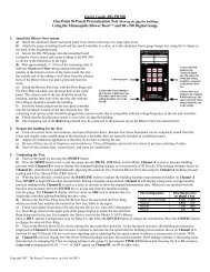
E.1 Quick Guide 1 – TrueFlow Air Handler Flow Meter and the DG-3 Gauge<br />
1. Measure the Normal System Operating Pressure (NSOP) with the existing filter in place.<br />
a) Locate the air handler system filter and replace if it is dirty.<br />
b) Install a static pressure probe into the ductwork at one of the 3 locations listed below:<br />
• Insert the static pressure probe into the side surface of the supply plenum. <strong>The</strong> side of the supply plenum<br />
chosen should not have a trunk line, distribution duct or supply register connected to it. <strong>The</strong> static pressure<br />
probe should point into the airstream.<br />
• Or, insert the tip of the static pressure probe into a "dead-end" corner of the supply plenum. A "dead-end"<br />
corner is a corner of the plenum that does not have a trunk line connection, distribution duct connection or<br />
supply register within 8 inches of the corner.<br />
• Or, insert the static pressure probe in the side surface of the return plenum. <strong>The</strong> side of the return plenum<br />
chosen should not have a trunk line, return duct or return register connected to it. <strong>The</strong> location chosen<br />
should also be at least 24 inches upstream from the TrueFlow Metering Plate, and at least 24 inches<br />
downstream from any 90 degree corners or return trunk line connections. <strong>The</strong> static pressure probe should<br />
point into the airstream. Note: if the Metering Plate will be installed at a remote filter grille, the static<br />
pressure probe may not be installed in the return plenum (i.e. install it in the supply plenum).<br />
c) Connect a piece of tubing between the static pressure probe and the Channel A Input tap. If the gauge is in the<br />
house during the test procedure, leave the Reference tap on Channel A open. If the gauge is not in the house during<br />
the test procedure (e.g. attic, crawlspace), run additional tubing from the Channel A Reference tap to inside the<br />
house.<br />
d) Turn the CHANNEL knob to "A", the RANGE switch to Low (200.0 Pa) and the MODE switch to Pressure.<br />
e) Turn on the air handler fan to the desired speed and record the normal system operating pressure (NSOP) from<br />
the gauge. You may want to use the 5 second, 10 second or long-term time-average setting if the reading is<br />
fluctuating.<br />
f) After recording the NSOP, turn off the air handler fan. Leave the static pressure probe in place and connected to<br />
the gauge.<br />
2. Install the TrueFlow Metering Plate in an Existing Filter Slot.<br />
a) Remove the existing filter and set it aside.<br />
b) Choose and assemble the metering plate and spacers needed to match the filter slot size.<br />
Filter Slot<br />
(in. x in.)<br />
Flow Metering Plate<br />
Spacer Dimension<br />
(in. x in.)<br />
Spacer 1 Spacer 2<br />
14 x 20 #14 ------ ------<br />
14 x 25 #14 5 x 14 ------<br />
16 x 20 #14 2 x 20 ------<br />
16 x 24 #14 2 x 20 4 x 16<br />
16 x 25 #14 2 x 20 5 x16<br />
18 x 20 #14 4 x 20 ------<br />
20 x 20 #20 ------ ------<br />
20 x 22 #20 2 x 20 ------<br />
20 x 24 #20 4 x 20 ------<br />
20 x 25 #20 5 x 20 ------<br />
20 x 30 #20 10 x 20 ------<br />
24 x 24 #20 4 x 20 4 x 24<br />
c) Install the assembled metering plate into the filter slot. Be sure the front side of the metering plate is facing into<br />
the air flow (front side has two diamond shaped labels on it). <strong>The</strong> H-channel gasket should provide a seal around the<br />
metering plate - all of the air flow should pass through the metering plate and not around it. Be sure that the ends of<br />
the flexible tubing connections attached to the plate's pressure sensing grids remain out of the filter slot. Occasionally,<br />
drilling holes into the ductwork may be required as a pathway for the ends of the flexible tubing. <strong>The</strong> flexible tubing<br />
can be passed through one of the plate's metering holes if this helps in getting the tubing ends outside of the filter slot.<br />
25 <strong>The</strong> ENERGY<br />
CONSERVATORY<br />
DIAGNOSTIC TOOLS TO MEASURE BUILDING PERFORMANCE
Appendix E<br />
Quick Guides<br />
• Obstructions within 6 inches upstream or 2 inches downstream of the metering plate that are blocking air flow<br />
through any of the metering holes may reduce the accuracy of the device.<br />
• If there is an obstruction and there is a spacer attached to the metering plate, try to<br />
install the metering plate so that the spacer is directly in front of the obstruction (this<br />
will minimize the effect of the obstruction on the flow measurement).<br />
• If the metering plate is installed directly downstream of a 90 degree bend in the duct<br />
system, and there is a spacer attached to the plate, install the metering plate so that the<br />
spacer is on the inside corner of the bend (see diagram to right).<br />
Spacer<br />
d) Close the filter access opening. Be careful not to pinch off the flexible tubing<br />
connections. Temporarily seal around the filter slot cover with masking tape to prevent air<br />
leakage.<br />
Note: If you are installing the metering plate at the filter grille of a single return duct system, simply push the plate<br />
into the empty filter rack. Make sure that the front of the metering plate is facing out (into the air flow). Keep the<br />
filter grille door open for the remainder of the test.<br />
3. Re-Measure the System Operating Pressure (TrueFlow Plate Installed).<br />
a) Turn the air handler fan back on to the same speed as Step 1 above.<br />
b) Measure and record the new system operating pressure (TFSOP) using the static pressure probe and Channel A<br />
of the DG-3. <strong>The</strong> static pressure probe should be in the exact same position as Step 1 above.<br />
4. Measure the Air Flow Through the TrueFlow Metering Plate<br />
a) Connect the flexible tubing connections from the metering plate<br />
to Channel B as shown in the diagram.<br />
b) In order for the DG-3 gauge to directly display air flow in CFM<br />
from the metering plate, the installed metering plate must be selected<br />
in the gauge. To select the metering plate being used in your test,<br />
first turn the MODE knob to the Fan Select position. <strong>The</strong> gauge<br />
display will show "-SEL" to indicate that a flow measurement device<br />
has not been selected. <strong>The</strong> selected flow measurement device is<br />
chosen by toggling up the SELECT Switch.<br />
Toggle up 3 times to select the #14 Metering Plate.<br />
Toggle up 4 times to select the #20 Metering Plate.<br />
PL 14 This indicates that you have chosen the #14<br />
TrueFlow Metering Plate.<br />
Turn the CHANNEL<br />
knob to B.<br />
SELECT Switch<br />
Connect Red tubing to the<br />
Channel B Input tap.<br />
Connect the Green tubing to the<br />
Channel B Reference tap.<br />
PL 20 This indicates that you have chosen the #20<br />
TrueFlow Metering Plate.<br />
Once the proper plate has been selected, turn the MODE switch to Flow. With the CHANNEL knob set to B, the gauge<br />
will now display the air flow through the metering plate in CFM. You may want to use the 5 second, 10 second or longterm<br />
time-average setting if the flow reading is fluctuating.<br />
Note: DG-3 gauges sold prior to March 2001 do not have the PL14 or PL20 options when selecting a flow measurement<br />
device. <strong>The</strong>se gauges can be retrofitted with a new EPROM by <strong>The</strong> <strong>Energy</strong> <strong>Conservatory</strong> (call for more information).<br />
Flow can also be determined by measuring the pressure signal from the metering plate, and using the Flow Conversion<br />
Table<br />
26 <strong>The</strong> ENERGY<br />
CONSERVATORY<br />
DIAGNOSTIC TOOLS TO MEASURE BUILDING PERFORMANCE
Appendix E<br />
Quick Guides<br />
5. Look up the Flow Resistance Correction Factor<br />
a) <strong>The</strong> Flow Resistance Correction Factor can be determined using the correction factor table provided with the<br />
manual, and the two system operating pressure measurements (Step 1 and Step 3). <strong>The</strong> Flow Resistance Correction<br />
Factor is used to adjust the measured air flow through the metering plate for differences in resistance between the<br />
existing filter and the TrueFlow Meter.<br />
6. Calculate the Adjusted Air Flow<br />
a) Multiply the measured air flow through the metering plate (Step 4) by the Flow Resistance Correction Factor<br />
(Step 5) to determine the final adjusted air flow amount. This result is the estimated air flow at the measurement<br />
location with the existing filter in place. Turn off the air handler fan.<br />
Note: When the TrueFlow Air Handler Flow Meter is installed at a remote filter grille, it is possible to make a correction<br />
to the measured flow through the metering plate which increases the accuracy of the flow measurement. See Appendix C<br />
of the TrueFlow manual for more details.<br />
27 <strong>The</strong> ENERGY<br />
CONSERVATORY<br />
DIAGNOSTIC TOOLS TO MEASURE BUILDING PERFORMANCE
Appendix E<br />
Quick Guides<br />
E.2 Quick Guide 2 – TrueFlow Air Handler Flow Meter and the DG-700 Gauge<br />
1. Measure the Normal System Operating Pressure (NSOP) with the existing filter in place.<br />
a) Locate the air handler system filter and replace if it is dirty.<br />
b) Install a static pressure probe into the ductwork at one of the 3 locations listed below:<br />
• Insert the static pressure probe into the side surface of the supply plenum. <strong>The</strong> side of the supply plenum<br />
chosen should not have a trunk line, distribution duct or supply register connected to it. <strong>The</strong> static pressure<br />
probe should point into the airstream.<br />
• Or, insert the tip of the static pressure probe into a "dead-end" corner of the supply plenum. A "dead-end"<br />
corner is a corner of the plenum that does not have a trunk line connection, distribution duct connection or<br />
supply register within 8 inches of the corner.<br />
• Or, insert the static pressure probe in the side surface of the return plenum. <strong>The</strong> side of the return plenum<br />
chosen should not have a trunk line, return duct or return register connected to it. <strong>The</strong> location chosen<br />
should also be at least 24 inches upstream from the TrueFlow Metering Plate, and at least 24 inches<br />
downstream from any 90 degree corners or return trunk line connections. <strong>The</strong> static pressure probe should<br />
point into the airstream. Note: if the Metering Plate will be installed at a remote filter grille, the static<br />
pressure probe may not be installed in the return plenum (i.e. install it in the supply plenum).<br />
c) Connect a piece of tubing between the static pressure probe and the Channel A Input tap. If the gauge is in the<br />
house during the test procedure, leave the Reference tap on Channel A open. If the gauge is not in the house during<br />
the test procedure (e.g. attic, crawlspace), run additional tubing from the Channel A Reference tap to inside the<br />
house.<br />
d) Turn on the air handler fan to the desired speed. Now turn on the gauge and put it the PR/ AH mode by pressing<br />
the MODE button 4 times. <strong>The</strong> icon “NSOP” will begin to flash in the Channel A display. At this point, the gauge is<br />
monitoring the real-time Channel A NSOP pressure, but is not recording the reading. <strong>The</strong> Channel B display is not<br />
active at this time.<br />
e) Press the START button to begin the NSOP measurement<br />
procedure on Channel A. Once the START button is pressed, the<br />
NSOP icon stops flashing and the gauge begins recording a long term<br />
average NSOP pressure reading on Channel A. During the<br />
measurement procedure, the Channel B display is used as a timer to<br />
let the user know how long (in seconds) the NSOP measurement has<br />
been active. <strong>The</strong> longer the measurement time, generally the more<br />
stable the reading typically becomes. In the screen to the right, the measured NSOP pressure is 56.7 Pascals<br />
(measured over the past 30 seconds).<br />
f) Once you are satisfied with the NSOP reading, press the ENTER key to accept and enter the reading into the<br />
gauge. Turn off the air handler fan, and leave the static pressure probe in place and connected to the gauge on<br />
Channel A.<br />
2. Install the TrueFlow Metering Plate in an Existing Filter Slot.<br />
a) Remove the existing filter and set it aside.<br />
b) Choose and assemble the metering plate and spacers needed to match the filter slot size.<br />
Filter Slot<br />
(in. x in.)<br />
Flow Metering Plate<br />
Spacer Dimension<br />
(in. x in.)<br />
Spacer 1 Spacer 2<br />
14 x 20 #14 ------ ------<br />
14 x 25 #14 5 x 14 ------<br />
16 x 20 #14 2 x 20 ------<br />
16 x 24 #14 2 x 20 4 x 16<br />
16 x 25 #14 2 x 20 5 x16<br />
18 x 20 #14 4 x 20 ------<br />
20 x 20 #20 ------ ------<br />
20 x 22 #20 2 x 20 ------<br />
20 x 24 #20 4 x 20 ------<br />
20 x 25 #20 5 x 20 ------<br />
20 x 30 #20 10 x 20 ------<br />
24 x 24 #20 4 x 20 4 x 24<br />
28 <strong>The</strong> ENERGY<br />
CONSERVATORY<br />
DIAGNOSTIC TOOLS TO MEASURE BUILDING PERFORMANCE
Appendix E<br />
Quick Guides<br />
c) Install the assembled metering plate into the filter slot. Be sure the front side of the metering plate is facing into<br />
the air flow (front side has two diamond shaped labels on it). <strong>The</strong> H-channel gasket should provide a seal around the<br />
metering plate - all of the air flow should pass through the metering plate and not around it. Be sure that the ends of<br />
the flexible tubing connections attached to the plate's pressure sensing grids remain out of the filter slot. Occasionally,<br />
drilling holes into the ductwork may be required as a pathway for the ends of the flexible tubing. <strong>The</strong> flexible tubing<br />
can be passed through one of the plate's metering holes if this helps in getting the tubing ends outside of the filter slot.<br />
• Obstructions within 6 inches upstream or 2 inches downstream of the metering plate that are blocking air<br />
flow through any of the metering holes may reduce the accuracy of the device.<br />
• If there is an obstruction and there is a spacer attached to the metering plate,<br />
try to install the metering plate so that the spacer is directly in front of the<br />
obstruction (this will minimize the effect of the obstruction on the flow<br />
measurement).<br />
• If the metering plate is installed directly downstream of a 90 degree bend in<br />
the duct system, and there is a spacer attached to the plate, install the metering<br />
plate so that the spacer is on the inside corner of the bend (see diagram to<br />
right).<br />
Spacer<br />
d) Close the filter access opening. Be careful not to pinch off the flexible tubing<br />
connections. Temporarily seal around the filter slot cover with masking tape to prevent<br />
air leakage.<br />
Note: If you are installing the metering plate at the filter grille of a single return duct system, simply push the plate<br />
into the empty filter rack. Make sure that the front of the metering plate is facing out (into the air flow). Keep the<br />
filter grille door open for the remainder of the test.<br />
3. Connect the Metering Plate to the DG-700.<br />
a) Connect the tubing from the<br />
installed metering plate to the<br />
DG-700. Connect the Red ("total<br />
pressure grid") tubing<br />
connection to the Channel B<br />
Input pressure tap. Connect the<br />
Green ("static pressure grid")<br />
tubing connection to the<br />
Channel B Reference pressure<br />
tap.<br />
Channel A Input tap<br />
should remain connected to<br />
the static pressure probe.<br />
Connect Red tubing to the<br />
Channel B Input tap<br />
Connect the Green tubing to the<br />
Channel B Reference tap.<br />
4. Measure the TrueFlow System Operating Pressure (TFSOP) and Adjusted Total Air Handler Flow.<br />
a) Check and adjust if necessary the selected test Device and Configuration shown in the upper part of the gauge<br />
display to match the metering plate installed in Step 2 above. When using the TrueFlow Metering Plates, the Device<br />
icon should always be set to TF, and the Configuration icon should be set to 14 or 20 depending on which metering<br />
plate is installed. Changes to the selected Device and Configuration are made by pressing the DEVICE and CONFIG<br />
buttons.<br />
29 <strong>The</strong> ENERGY<br />
CONSERVATORY<br />
DIAGNOSTIC TOOLS TO MEASURE BUILDING PERFORMANCE
Appendix E<br />
Quick Guides<br />
b) Turn the air handler fan back on to the same speed as used<br />
in Step 1 above. Channel A will now display the TFSOP<br />
reading from the static pressure probe, and Channel B will<br />
display adjusted air handler flow. <strong>The</strong> static pressure probe<br />
should be in exactly the same position as it was in Step 1 above.<br />
<strong>The</strong> air handler flow rate estimate shown on Channel B is<br />
determined by continuously adjusting the measured air flow<br />
from the TrueFlow Metering Plate using a flow resistance correction factor calculated from the NSOP and TFSOP<br />
pressure readings. If the readings are fluctuating, change the time averaging setting to 5 second, 10 second, or Long-<br />
Term average using the TIME AVG button.<br />
c) Record the adjusted air flow reading from Channel B. In the screen to the right, the adjusted air flow reading is<br />
1,566 CFM. This result is the estimated air flow at the measurement location with the existing filter in place. Turn off<br />
the air handler fan.<br />
Note: When the TrueFlow Air Handler Flow Meter is installed at a remote filter grille, it is possible to make a correction<br />
to the measured flow through the metering plate which increases the accuracy of the flow measurement. See Appendix C<br />
of the TrueFlow manual for more details.<br />
30 <strong>The</strong> ENERGY<br />
CONSERVATORY<br />
DIAGNOSTIC TOOLS TO MEASURE BUILDING PERFORMANCE
Appendix F<br />
References<br />
Appendix F<br />
References<br />
D. Parker, 2000, "Summary of Impacts of Refrigerant Charge, Air Flow and Maintenance Issues for Residential Air<br />
Conditioning Systems", Proceedings of the ACEEE 2000 Summer Study on <strong>Energy</strong> Efficiency in Buildings.<br />
D. Parker et al., 1997, "Impact of Evaporator Coil Airflow in Residential Air Conditioning Systems", ASHRAE<br />
Transactions, Vol. 103, Pt.2.<br />
M. Blasnik et al., 1996. "Assessment of HVAC Installations in New Homes in APS Service Territory", Proctor<br />
Engineering Group.<br />
M. Blasnik et al., 1995. "Assessment of HVAC Installation in New Homes in Nevada Power Company's Service<br />
Territory", Proctor Engineering Group.<br />
J. Proctor, 1990, "Pacific Gas and Electric Appliance Doctor Pilot Project", Proctor Engineering Group.<br />
31 <strong>The</strong> ENERGY<br />
CONSERVATORY<br />
DIAGNOSTIC TOOLS TO MEASURE BUILDING PERFORMANCE