Create successful ePaper yourself
Turn your PDF publications into a flip-book with our unique Google optimized e-Paper software.
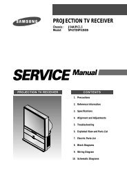
SECTION 4<br />
ADJUSTMENT<br />
4.1 Before adjustment<br />
4.1.1 Precaution<br />
• The adjustments of this unit inclu<strong>de</strong> the mechanism compatibility<br />
and electrical adjustments. During the performance<br />
of this work, be sure to observe the precautions for<br />
each type of adjustment.<br />
• If there is a reference to a signal input method in the signal<br />
column of the adjustment chart, “Ext. S-input” means the<br />
Y/C separated vi<strong>de</strong>o signal and “Ext. input” means the<br />
composite vi<strong>de</strong>o signal input.<br />
• Unless otherwise specified, all measuring points and<br />
adjustment parts are located on the Main board.<br />
4.1.2 Required <strong>test</strong> equipments<br />
• Color (colour) television or monitor<br />
• Oscilloscope: wi<strong>de</strong>-band, dual-trace, triggered <strong>de</strong>layed sweep<br />
• Signal generator: RF / IF sweep / marker<br />
• Signal generator: stairstep, color (colour) bar [NTSC]<br />
• Recording tape<br />
• Digit-key remote controller(provi<strong>de</strong>d)<br />
4.1.3 Required adjustment tools<br />
• : Used --- : Not used<br />
Mechanism<br />
compatibility<br />
adjustment<br />
Electrical<br />
adjustment<br />
Roller driver • ---<br />
Jig RCU --- •<br />
Back tension cassette gauge • ---<br />
Alignment tape(MHP) • ---<br />
Alignment tape(MHP-L) • •<br />
Roller driver<br />
PTU94002<br />
Alignment tape<br />
(SP, stairstep, NTSC)<br />
MHP<br />
Jig RCU<br />
PTU94023B<br />
Alignment tape<br />
(EP, stairstep, NTSC)<br />
MHP-L<br />
Back tension cassette gauge<br />
PUJ48076-2<br />
4.1.4 Color (colour) bar signal,Color (colour) bar pattern<br />
1V<br />
Color(colour) bar signal [NTSC]<br />
White(75%)<br />
100 IRE<br />
40 IRE<br />
Horizontal sync<br />
White(100%)<br />
Q<br />
Yellow<br />
Cyan<br />
Green<br />
Magenta<br />
Red<br />
Blue<br />
I<br />
Burst<br />
40 IRE<br />
Color(colour) bar pattern [NTSC]<br />
(75%)<br />
White<br />
Yellow<br />
Cyan<br />
Green<br />
Magenta<br />
Red<br />
White<br />
Q<br />
100%<br />
I Black<br />
Blue<br />
4.1.5 Switch settings<br />
When adjusting this unit, set the VCR mo<strong>de</strong> and switches<br />
as <strong>de</strong>scribed below.<br />
• When using the Jig RCU, it is required to set the VCR to the<br />
Jig RCU mo<strong>de</strong> (the mo<strong>de</strong> in which co<strong>de</strong>s from the Jig RCU can<br />
be received). (See "section 2 SPECIFIC <strong>SERVICE</strong> INSTRUC-<br />
TIONS".)<br />
Jig RCU<br />
[Data transmitting method]<br />
Depress the " "( 3 ) button<br />
after the data co<strong>de</strong> is set.<br />
CUSTOM CODE<br />
43: A CODE<br />
DATA CODE<br />
Fig.4-1 Jig RCU [PTU94023B]<br />
• Set the switches as shown below unless otherwise specified<br />
on the relevant adjustment chart. The switches that are not listed<br />
below can be set as <strong>de</strong>sired.<br />
If the VCR is not equipped with the functions <strong>de</strong>tailed below,<br />
setup is not required.<br />
AUTO PICTURE/VIDEO CALIBRATION/<br />
B.E.S.T./D.S.P.C.<br />
PICTURE CONTROL/SMART PICTURE<br />
VIDEO STABILIZER<br />
TBC<br />
Digital 3R<br />
VIDEO NAVIGATION/TAPE MANAGER<br />
BLUE BACK<br />
OFF<br />
INITIAL MODE<br />
NORMAL/NATURAL<br />
OFF<br />
ON<br />
ON<br />
OFF<br />
OFF<br />
4.1.6 Manual tracking mo<strong>de</strong> (Auto tracking ON/OFF) setting<br />
(1) In or<strong>de</strong>r to set to the manual tracking mo<strong>de</strong> during tape<br />
playback, press the “SP/EP(LP)”button on the remote control<br />
unit.<br />
• Each press of the button switches the auto tracking ON<br />
or OFF.<br />
• When the manual tracking mo<strong>de</strong> is set, the tracking is<br />
placed at the center position.<br />
(2) Press “channel +/-” to adjust the tracking manually.<br />
4.1.7 EVR Adjustment<br />
Some of the electrical adjustments require the adjustment performed<br />
by the EVR system. The main unit have EEPROMs for<br />
storing the EVR adjustment data and user setups.<br />
Notes:<br />
• In the EVR adjustment mo<strong>de</strong>, the value is varied with the<br />
channel buttons (+, -). The adjusted data is stored when<br />
the setting mo<strong>de</strong> changes (from PB to STOP, when the<br />
tape speed is changed, etc.). Take care to i<strong>de</strong>ntify the<br />
current mo<strong>de</strong> of each adjustment item when making an<br />
adjustment.<br />
• When changing the address setting in the EVR adjustment<br />
mo<strong>de</strong>, use the Jig RCU or the remote controller<br />
having numeric keypad with which a numeric co<strong>de</strong> can<br />
be directly input.<br />
The remote control co<strong>de</strong> of the Jig RCU corresponds to<br />
each of the digit keys on the remote controller as follows.<br />
1-10 (No.YD006)