You also want an ePaper? Increase the reach of your titles
YUMPU automatically turns print PDFs into web optimized ePapers that Google loves.
4.3.2.2 EE Y level<br />
Signal<br />
(A1)<br />
(A2)<br />
• Ext. input<br />
• Color (colour) bar signal<br />
Mo<strong>de</strong> (B) • EE<br />
Equipment (C) • Oscilloscope<br />
Measuring point (D) • Y OUT (S terminal)<br />
EVR mo<strong>de</strong><br />
EVR address<br />
(F1)<br />
(F2)<br />
(F3)<br />
(F4)<br />
(F5)<br />
• Jig co<strong>de</strong> “95”<br />
• "ADJUST02 : **"<br />
• Jig co<strong>de</strong> “22”<br />
• Jig co<strong>de</strong> “18” or “19” (Channel +/-)<br />
• Jig co<strong>de</strong> “3C”<br />
Specified value (G) • 1.00 ± 0.02 Vp-p (terminated)<br />
Adjustment tool (H) • Jig RCU [PTU94023B]<br />
(1) Observe the Y OUT waveform at the measuring point (D).<br />
(2) Set the VCR to the EVR mo<strong>de</strong> by transmitting the co<strong>de</strong> (F1)<br />
from the Jig RCU.<br />
(3) Set the EVR address to (F2) by transmitting the co<strong>de</strong> (F3)<br />
from the Jig RCU.<br />
(4) Transmit the co<strong>de</strong> (F4) from the Jig RCU to adjust so that<br />
the Y level of the Y OUT waveform becomes the specified<br />
value (G).<br />
(5) Release the EVR mo<strong>de</strong> of the VCR by transmitting the<br />
co<strong>de</strong> (F5) from the Jig RCU again. (When the EVR mo<strong>de</strong><br />
is released, the adjusted data is memorized.)<br />
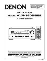
H. rate<br />
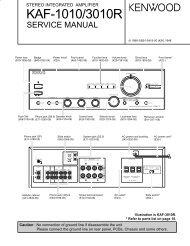
Fig.4-3c EE Y level<br />
4.3.2.3 EE COMPONENT PB/CB level<br />
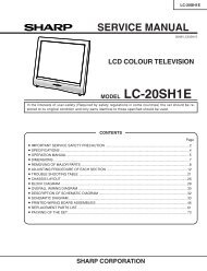
Y level<br />
PB/CB level<br />
Fig.4-3d EE component PB/CB level<br />
4.3.3 Syscon circuit<br />
Notes:<br />
• When perform this adjustment, remove the Mechanism<br />
assembly.<br />
4.3.3.1 Timer clock<br />
Signal (A) • No signal<br />
Mo<strong>de</strong> (B) • EE<br />
Equipment (C) • Frequency counter<br />
Measuring point (D1) • IC3001 pin 61<br />
(D2) • IC3001 pin 24<br />
(D3) • C3026 + and -<br />
Adjustment part (F) • C3025 (TIMER CLOCK)<br />
Specified value (G) • 1024.008 ± 0.001 Hz<br />
(976.5549 ± 0.0010 usec)<br />
(1) Connect the frequency counter to the measuring point<br />
(D1).<br />
(2) Connect the short wire between the short point (D2) and<br />
Vcc (5V).<br />
(3) Short the leads of capacitor (D3) once in or<strong>de</strong>r to reset<br />
the microprocessor of the Syscon.<br />
(4) Disconnect the short wire between the short point (D2)<br />
and Vcc then connect it again.<br />
(5) Adjust the Adjustment part (F) so that the output frequency<br />
becomes the specified value (G).<br />
Signal (A) • Internal color bar<br />
Mo<strong>de</strong> (B) • EE<br />
Equipment (C) • Oscilloscope<br />
Measuring point (D) • COMPONENT PB/CB terminal<br />
EVR mo<strong>de</strong><br />
EVR address<br />
(F1)<br />
(F2)<br />
(F3)<br />
(F4)<br />
(F5)<br />
• Jig co<strong>de</strong> “95”<br />
• "ADJUST06 : **"<br />
• Jig co<strong>de</strong> “26”<br />
• Jig co<strong>de</strong> “18” or “19” (Channel +/-)<br />
• Jig co<strong>de</strong> “3C”<br />
Specified value (G) • 0.70 ± 20 Vp-p (terminated)<br />
Adjustment tool (H) • Jig RCU [PTU94023B]<br />
(1) Observe the CB OUT waveform at the measuring point (D).<br />
(2) Set the VCR to the EVR mo<strong>de</strong> by transmitting the co<strong>de</strong> (F1)<br />
from the Jig RCU.<br />
(3) Set the EVR address to (F2) by transmitting the co<strong>de</strong> (F3)<br />
from the Jig RCU.<br />
(4) Transmit the co<strong>de</strong> (F4) from the Jig RCU to adjust so that<br />
the CB level of the CB OUT waveform becomes the specified<br />
value (G).<br />
(5) Release the EVR mo<strong>de</strong> of the VCR by transmitting the<br />
co<strong>de</strong> (F5) from the Jig RCU again. (When the EVR mo<strong>de</strong><br />
is released, the adjusted data is memorized.)<br />
1-14 (No.YD006)