Create successful ePaper yourself
Turn your PDF publications into a flip-book with our unique Google optimized e-Paper software.
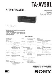
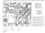
Proper waveform variation<br />
Improper waveform variation<br />
Up Down<br />
A<br />
C<br />
B<br />
D<br />
Roller driver<br />
Gui<strong>de</strong> roller<br />
(supply si<strong>de</strong>)<br />
Fig.4-2c<br />
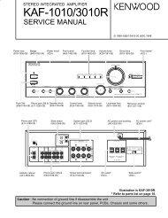
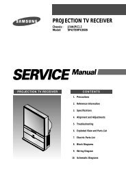
4.2.3 Height and tilt of the A/C head<br />
Note:<br />
• Set a temporary level of the height of the A/C head in advance<br />
to make the adjustment easier after the A/C head<br />
has been replaced. (Refer to the <strong>SERVICE</strong> <strong>MANUAL</strong><br />
No.86700 [MECHANISM ASSEMBLY].)<br />
Signal (A) • Alignment tape(SP, stairstep, NTSC) [MHP]<br />
Mo<strong>de</strong> (B) • PB<br />
Equipment (C) • Oscilloscope<br />
Measuring point (D1)<br />
(D2)<br />
• TP106 (PB. FM)<br />
• TP4001 (CTL. P)<br />
External trigger (E) • TP111 (D.FF)<br />
Adjustment part (F) • A/C head [Mechanism assembly]<br />
Specified value (G) • Maximum waveform<br />
(1) Play back the alignment tape (A).<br />
(2) Apply the external trigger signal to D.FF (E), to observe the<br />
AUDIO OUT waveform and Control pulse waveform at the<br />
measuring points (D1) and (D2) in the ALT mo<strong>de</strong>.<br />
(3) Set the VCR to the manual tracking mo<strong>de</strong>.<br />
(4) Adjust the AUDIO OUT waveform and Control pulse waveform<br />
by turning the screws (1), (2) and (3) little by little until<br />
both waveforms reach maximum. The screw (1)<br />
and (3) are for adjustment of tilt and the screw (2) for azimuth.<br />
(2)<br />
Head base<br />
(1)<br />
AUDIO OUT<br />
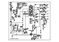
4.2.4 A/C head phase (X-value)<br />
Signal (A1)<br />
(A2)<br />
• Alignment tape(SP, stairstep, NTSC) [MHP]<br />
• Alignment tape(EP,stairstep,NTSC) [MHP-L]<br />
Mo<strong>de</strong> (B) • PB<br />
Equipment (C) • Oscilloscope<br />
Measuring point (D) • TP106 (PB. FM)<br />
External trigger (E) • TP111 (D.FF)<br />
Adjustment part (F) • A/C head base [Mechanism assembly]<br />
Specified value (G) • Flat V.PB FM waveform<br />
Adjustment tool (H) • Roller driver [PTU94002]<br />
(1) Play back the alignment tape (A1).<br />
(2) Apply the external trigger signal to D.FF (E), to observe the<br />
V.PB FM waveform at the measuring point (D).<br />
(3) Set the VCR to the manual tracking mo<strong>de</strong>.<br />
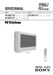
(4) Loosen the screws (4) and (5), then set the Roller driver to<br />
the innermost projected part of the A/C head. (See Fig. 4-<br />
2e.)<br />
(5) Rotate the roller driver so that the A/C head comes closest<br />
to the capstan. From there, move the A/C head back gradually<br />
toward the drum until the point where the FM waveform<br />
is maximized for the second time, and then<br />
tighten the screws (4) and (5) temporarily.<br />
(6) Play an alignment tape (A2) and set to the manual-tracking<br />
mo<strong>de</strong>.<br />
(7) Fine-adjust A/C head base position to maximize the FM<br />
waveform, and then tighten the screws (4) and (5) firmly.<br />
(8) Play alignment tapes (A1) and (A2) and confirm that the FM<br />
waveforms are maximized when the tracking is at the center<br />
position.<br />
To the drum<br />
Toward the capstan<br />
Toward the drum<br />
A/C head<br />
Waveform output<br />
Screw (5)<br />
Roller driver<br />
Screw (4)<br />
Head base<br />
To the capstan<br />
Fig.4-2e<br />
Alignment tape<br />
[SP, stairstep]<br />
played with the<br />
SP head<br />
Alignment tape<br />
[EP(LP), stairstep]<br />
played with the<br />
EP(LP) head<br />
X-value adjustment point<br />
Drum si<strong>de</strong> Control head position Capstan si<strong>de</strong><br />
A/C head<br />
(3)<br />
Fig.4-2d<br />
CTL.P<br />
Fig.4-2f<br />
Maximum<br />
1-12 (No.YD006)