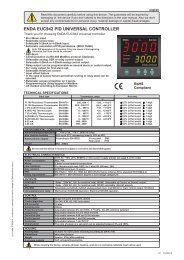
enda euc442 pid universal controller - SURAN Industrieelektronik
enda euc442 pid universal controller - SURAN Industrieelektronik
enda euc442 pid universal controller - SURAN Industrieelektronik

Create successful ePaper yourself
Turn your PDF publications into a flip-book with our unique Google optimized e-Paper software.
Read this document carefully before using this device. The guarantee will be expired by<br />
damaging of the device if you don't attend to the directions in the user manual. Also we don't<br />
accept any compensations for personal injury, material damage or capital disadvantages.<br />
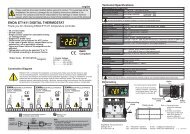
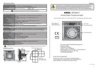
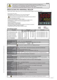
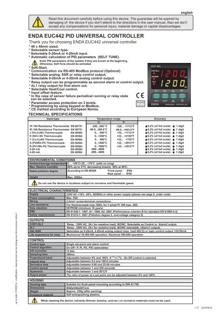
ENDA EUC442 PID UNIVERSAL CONTROLLER<br />
Thank you for choosing ENDA EUC442 <strong>universal</strong> <strong>controller</strong>.<br />
* 48 x 48mm sized.<br />
* Selectable sensor type.<br />
* Selectable 0-20mA or 4-20mA input.<br />
* Automatic calculation of PID parameters (SELF TUNE).<br />
Enter PID parameters of the system if they are known at the beginning.<br />
Otherwise, Self-Tune should be activated.<br />
* Soft-Start.<br />
* Communication via<br />
RS-485 ModBus protocol (Optional).<br />
* Selectable analog, SSR or relay control output.<br />
* Selectable 0-20mA or 4-20mA analog control output.<br />
* Relay output can be programmable as second alarm or control output.<br />
* AL1 relay output for first alarm out.<br />
* Selectable Heat/Cool control.<br />
* Input offset feature.<br />
* In the case of sensor failure periodical running or relay state<br />
can be selected.<br />
* Parameter access protection on 3 levels.<br />
* Programming by using keypad or Modbus.<br />
* CE marked according to European Norms.<br />
TECHNICAL SPECIFICATIONS<br />
Input type Temperature range Accuracy<br />
°C °F<br />
Pt 100 Resistance Thermometer EN 60751<br />
Pt 100 Resistance Thermometer EN 60751<br />
-200...600 °C<br />
-99.9...300.0°C<br />
-328... +1112°F<br />
-99.9...+543.0°F<br />
0,2% ( of full scale)<br />
0,2% ( of full scale)<br />
J (Fe-CuNi) Thermocouple<br />
K (NiCr-Ni) Thermocouple<br />
EN 60584<br />
EN 60584<br />
0... 600°C<br />
0...1200°C<br />
+32... +1112°F<br />
+32... +2192°F<br />
0,2% ( of full scale)<br />
0,2% ( of full scale)<br />
T (Cu-CuNi) Thermocouple EN 60584 0... 400°C<br />
+32... +752°F<br />
0,2% ( of full scale)<br />
S (Pt/0Rh-Pt) Thermocouple<br />
R (Pt13Rh-Pt) Thermocouple<br />
0-20 mA<br />
4-20 mA<br />
EN 60584<br />
EN 60584<br />
EN 60584<br />
EN 60584<br />
0...1600°C<br />
0...1600°C<br />
-999...4000<br />
-999...4000<br />
+32... +2912°F<br />
+32... +2912°F<br />
0,2% ( of full scale)<br />
0,2% ( of full scale)<br />
0,2% ( of full scale)<br />
0,2% ( of full scale)<br />
ENVIRONMENTAL CONDITIONS<br />
Ambient/storage temperature 0 ... +50 °C/<br />
-25... +70°C (with no icing)<br />
Max. Relative humidity 80% up to 31°C decreasing linearly 50%<br />
at 40 °C.<br />
Rated pollution degree According to EN 60529 Front panel : IP65<br />
Rear panel : IP20<br />
Height<br />
Max. 2000m<br />
Do not use the device in locations subject to corrosive and flammable gases.<br />
RoHS<br />
conform<br />
EUC 442<br />
CNT/AL2<br />
AN/SSR<br />
AL1<br />
SET<br />
CSET<br />
ENDA<br />
ASET<br />
1 digit<br />
1 digit<br />
1 digit<br />
1 digit<br />
1 digit<br />
1 digit<br />
1 digit<br />
1 digit<br />
1 digit<br />
english<br />
PV<br />
SV<br />
UNIVERSAL CONTROLLER<br />
up to date: 01022014, modification reserved and can be change any time previous notice !<br />
ELECTRICAL CHARACTERISTICS<br />
Supply<br />
230V AC +10% -20%, 50/60Hz or other power supply (please see page 5, order code)<br />
Power consumption Max. 5VA<br />
Wiring<br />
2.5mm² screw-terminal connections<br />
Line resistance<br />
For thermocouple max.100 Ù, for 3 wired Pt 100 max. 20Ù<br />
Data retention<br />
EEPROM (minimum 10 years)<br />
EMC<br />
EN 61326-1: 1997, A1: 1998, A2: 2001 (Performance criterion B for standard EN 61000-4-3)<br />
Safety requirements EN 61010-1: 2001 (Pollution degree 2, overvoltage category II)<br />
OUTPUTS<br />
CONT./AL2<br />
AL1<br />
ANL/SSR<br />
Life expectancy for relay<br />
CONTROL<br />
Control type<br />
Control algorithm<br />
A/D converter<br />
Sampling time<br />
Proportional band<br />
Integral time<br />
Derivative time<br />
Control period<br />
Hysteresis<br />
Output power<br />
Relay : 250V AC, 2A ( for resistive load), NO/NC. Selectable as Control or Alarm2 output.<br />
Relay : 250V AC, 2A ( for resistive load), NO/NC selectable. (Alarm1 output).<br />
Selectable as 0-20mA, 4-20mA analog output (max. load 400 Ù) or logic control output 12V/20mA<br />
Mechanical 30.000.000 operation; Electrical 300.000 operation<br />
Single set-point and alarm control<br />
On-Off / P, PI, PD, PID (selectable)<br />
15 bits<br />
500ms<br />
Adjustable between 0% and 100 %. If Pb=<br />
0%<br />
, On-Off control is selected.<br />
Adjustable between 0.0 and 100.0 minutes<br />
Adjustable between 0.00 and 25.00 minutes<br />
Adjustable between 1 and 250 seconds<br />
Adjustable between 1 and 50°C/F<br />
The ratio of power at a set point can be adjusted between 0% and 100%<br />
HOUSING<br />
Housing type Suitable for flush-panel mounting according to DIN 43 700.<br />
Dimensions<br />
W48xH48xD87mm<br />
Weight<br />
Approx. 250g (after packing)<br />
Enclosure material Self extinguishing plastics.<br />
While cleaning the device, solvents (thinner, benzine, acid etc.) or corrosive materials must not be used.<br />
1./5 EUC442-E
SET<br />
CSET<br />
ASET<br />
SET<br />
If key is pressed while holding key, the programming mode is enabled.<br />
ASET<br />
CSET<br />
Con.o.<br />
ASET<br />
ALr.o.<br />
ASET<br />
ConF.<br />
ASET<br />
Page 3/5<br />
Pb<br />
4<br />
tý<br />
4.0<br />
td<br />
1.00<br />
Ct<br />
20<br />
P.SEt.<br />
0<br />
C.HyS.<br />
2<br />
C.StA.<br />
HEAt<br />
Pr.Er.<br />
0<br />
C.oT.S.<br />
Out1<br />
S.S.T.S.<br />
0<br />
A.o.L.L.<br />
Pb = Proportional band.<br />
Adjustable between 0% and 100%<br />
Setting Pb = 0% On-Off control<br />
is selected.<br />
Ti = Integral time.<br />
Adjustable between 0.0 and 100.0 minutes.<br />
If ti = 0.0, integral effect is not used.<br />
Setting Pb = 0 this parameter is not seen.<br />
td = Derivative time.<br />
Adjustable between 0.00 and 25.00 minutes.<br />
If td = 0.00, derivation effect is not used.<br />
Setting Pb = 0 this parameter is not seen.<br />
Ct = Control period.<br />
Adjustable between 1 and 250 seconds.<br />
Setting Pb = 0 andC.ot.S. = Out1 this<br />
parameter is not seen.<br />
P.SEt. = The ratio of output power at the set<br />
point.Adjustable between 0% and 100%.<br />
If this parameter is set to 0, the output power<br />
becomes 0 at the set point. If it is adjusted to<br />
50% output power becomes 50% at the set<br />
point. Using this parameter the energy<br />
requirements of the system is adjusted at the<br />
set point. So the set point can be achieved by<br />
minimum fluctuations and in the shortest time.<br />
Setting Pb = 0, this parameter is not seen.<br />
C/HYS. = Hysteresis of the control<br />
output.<br />
Adjustable between 1 and 50 °C/F.<br />
C.StA. = Configuration of the control output.<br />
C.StA.<br />
= HEAt means heating control.<br />
C.StA. = cooL means cooling control.<br />
Pr.Er. = This parameter is used to adjust the<br />
control output during a sensor failure.<br />
Adjustable between 0% and 100%.<br />
If this parameter is adjusted to a value closer to<br />
the energy requirements of the system at the set<br />
point, process temperature is prevented to rise or<br />
drop to dangerous levels.<br />
C.ot.S. = Type of control output (PID)<br />
out1 = Out1 is control output.<br />
020 - = Analog output is control output.<br />
( 0mA %0 energy, 20mA %100 energy)<br />
Out1 = Alarm2 output.<br />
420 - = Analog output is control output.<br />
( 4mA %0 energy, 20mA %100 energy)<br />
Out1 = Alarm2 output.<br />
s.s.r = SSR is control output..<br />
Out1 = Alarm2 output.<br />
S.S.t.S. = Soft Star timer set point value<br />
This parameter indicates the time to reach set<br />
point value when the device is first enegised.<br />
Adjustable between 0 and 250 minutes.<br />
If 0 is selected, soft start feature will be enable<br />
and the device reaches set point value quickly.<br />
NOTE! Setting Pb = 0, softstart feature will be<br />
disable.<br />
A.o.L.L. =Minimum analog output value (%<br />
output) ,adjustable between 0 and 100.<br />
A1. Hy.<br />
2<br />
A1.tp.<br />
ýndE.<br />
A1.St.<br />
Hý.<br />
A1.P.e.<br />
oFF<br />
A2. Hy.<br />
2<br />
A2.tp.<br />
ýndE.<br />
A2.St.<br />
Hý.<br />
A2.P.e.<br />
oFF<br />
A1. Hy. = Hysteresis of the Alarm1<br />
output.<br />
Adjustable between 1 and 50°C.<br />
A1.tP. = Function of Alarm1 output.<br />
Four kinds of functions can be<br />
selected.<br />
indE. = Independent<br />
dE. = Deviation<br />
bAnd = Band<br />
bAn.i. = Band with inhibition<br />
A1.St. = The state of Alarm1.<br />
If independent or deviation alarm is<br />
selected, this parameter can be Lo.<br />
and Hi. . For Lo.<br />
alarm output is<br />
energised below the alarm set point.<br />
For Hi.<br />
alarm output is energized<br />
above the alarm set point. If band<br />
alarm is selected, this parameter can<br />
bebIHI orboHI.<br />
bIHI means<br />
alarm is activated inside the band.<br />
boHI means alarm is activated<br />
outside the band.<br />
A1.p.e. = State of Alarm1 output in<br />
the case of sensor failure.<br />
If A1.p.e.=<br />
On , the alarm output is<br />
energised during the sensor failure.<br />
If A1.p.e. = oFF, the alarm output is not<br />
energized during the sensor failure.<br />
A2. Hy. = Hysteresis of the Alarm2<br />
output.<br />
Adjustable between 1 and 50°C.<br />
NOTE! IfC.ot.S. = .out1, this<br />
parameter is not seen.<br />
A2.tP. = Function of Alarm2 output.<br />
Four kinds of functions can be<br />
selected.<br />
indE. = Independent<br />
dE. = Deviation<br />
bAnd = Band<br />
bAn.i. = Band with inhibition<br />
NOTE! IfC.ot.S. = .out1, this<br />
parameter is not seen.<br />
A2.St. = The state of Alarm2.<br />
If independent or deviation alarm is<br />
selected, this parameter can be Lo.<br />
and Hi ..<br />
For Lo.<br />
alarm output is<br />
energised below the alarm set point.<br />
For Hi.<br />
alarm output is energized<br />
above the alarm set point. If band<br />
alarm is selected, this parameter can<br />
be bIHI or boHI. bIHI means alarm is<br />
activated inside the band. boHI means<br />
alarm is activated outside the band.<br />
NOTE! If C.ot.S. = . out1, this<br />
parameter is not seen.<br />
A2.p.e. = State of Alarm2 output in<br />
the case of sensor failure.<br />
If A2.p.e.<br />
= On, the alarm output is<br />
Energised during the sensor failure.<br />
If A2.p.e.<br />
= oFF, the alarm output is not<br />
energized during the sensor failure.<br />
NOTE! If C.ot.S.<br />
= . out1, this<br />
parameter is not seen.<br />
ýnP.<br />
FE.cn.<br />
C.Hi.L.<br />
600<br />
C.Lo.L.<br />
0<br />
oFFS.<br />
0<br />
Unit.<br />
°C<br />
A1.H.L.<br />
600<br />
A1.L.L.<br />
0<br />
A2.H.L.<br />
600<br />
A2.L.L..<br />
0<br />
fL.Co.<br />
4<br />
inP. = Type of input and scale.<br />
Pt = Pt 100 -200 to +600°C<br />
Pt.0 = Pt 100 -99.0 to +300.0°C<br />
FE.cn. = J (Iron vs. Copper-Nickel) 0 to +600°C<br />
nc.nA.<br />
= K (Nickel-Cr.vs. Nickel-Alum.) 0 to +1200°C<br />
c.cn. = T (Copper vs. Copper-Nickel) 0 to +400°C<br />
P10.r. = S (Platinum-10%Rhodium vs. Pt.) 0 to +1600°C<br />
P13.r. = R (Platinum-13%Rhodium vs. Pt.) 0 to +1600°C<br />
020 - = 0-20 mA -999 to 4000<br />
420 - = 4-20 mA -999 to 4000<br />
Note : If the selected input type is changed, the value of<br />
C.Hi.L, C.Lo.L , A.Hi.L., A.Lo.L. parameters changes<br />
automatically.<br />
C.Hi.L. = Set point upper limit.<br />
IfInP. orUnIt.<br />
parameters are changed, the maximum<br />
value of the C.Hi.L. parameter changes to the<br />
maximum scale value of the selected input. The<br />
minimum value is the value of C.Lo.L. parameter.<br />
C.LoL. = Set point lower limit.<br />
If InP. or UnIt. parameters are changed, the minimum<br />
value of theC.Lo.L.<br />
parameter changes to the minimum<br />
scale value of the selected input. The maximum value is<br />
the value ofC.Hi.L.<br />
parameter.<br />
oFFS. = Offset value.<br />
Offset value is added to the measurement value.<br />
Adjusted between -99 and +99°C.<br />
The normal value is 0.<br />
UnIt = The temperature unit.<br />
Selectable as °C or °F.<br />
Note : If the temperature unit is changed, the value of<br />
the CHiL. , C.LoL. , A1HL, A1LL, A2HL, A2LL,<br />
Parameters changes automatically.<br />
NOTE! IfInp<br />
parameter is selected TC or Pt100, this<br />
parameter is seen.<br />
A1.H.L = Alarm1 value upper limit.<br />
IfInP. orUnIt.<br />
parameters are changed, the maximum<br />
value of theA1.H.L.<br />
parameter changes to the maximum<br />
scale value of the selected input type. Minimum of<br />
A1.H.L. parameter is the value ofA1.L.L.<br />
parameter.<br />
A1.L.L. = Alarm1 value lower limit.<br />
IfInP. orUnIt.<br />
parameters are changed, the minimum<br />
value of theA1.L.L.<br />
parameter changes to the minimum<br />
scale value of the selected input type. The maximum<br />
value is the value ofA1.H.L.<br />
parameter.<br />
A2.H.L = Alarm2 value upper limit.<br />
IfInP. orUnIt.<br />
parameters are changed, the maximum<br />
value of theA2.H.L.<br />
parameter changes to the maximum<br />
scale value of the selected input type. Minimum of<br />
A2.H.L. parameter is the value ofA2.L.L.<br />
parameter.<br />
NOTE! If C.ot.S. = . out1, this parameter is not seen.<br />
A2.L.L. = Alarm2 value lower limit.<br />
IfInP. orUnIt.<br />
parameters are changed, the minimum<br />
value of theA2.L.L.<br />
parameter changes to the minimum<br />
scale value of the selected input type. The maximum<br />
value is the value ofA2.H.L.<br />
parameter.<br />
NOTE! If C.ot.S. = . out1, this parameter is not seen.<br />
fL.Co. = Coefficient of digital filter.<br />
Filter for display value.<br />
Adjustable between 1 and 32. If this parameter is 1,<br />
digital filter runs most quick. If the parameter is 31, the<br />
filter run most slow. The value of parameter should be<br />
increased in interference.<br />
A.o.H.L.<br />
A.o.H.L. =Maximum analog output value (%<br />
output) ,adjustable between 0 and 100.<br />
ConF. Page 3/5<br />
Modification of Parameter<br />
C.HyS.<br />
6<br />
SET<br />
CSET<br />
C.HyS.<br />
6<br />
SET<br />
CSET<br />
C.HyS.<br />
5<br />
SET<br />
CSET<br />
C.HyS.<br />
6<br />
SET<br />
CSET<br />
SET<br />
When holding key, the value of parameter flashes and using keys the requested value can be adjusted.<br />
CSET<br />
If<br />
key is pressed and held 0.6 seconds, the value of the selected parameter changes ra<strong>pid</strong>ly. If waited enough,<br />
the value increases 100 at each step. After 1 second following the release of the key, initial condition is returned.<br />
The same procedure is valid for the decrement key.<br />
2./5 EUC442-E
Entering from the programming mode to the run mode:<br />
If no key is pressed within 20 seconds during programming mode, the data is stored automatically and the run mode is entered.<br />
Alternatively, the same function occurs first pressing key and then pressing keys together.<br />
ASET<br />
CSET ASET<br />
SET<br />
SET<br />
CSET<br />
ASET<br />
Page 2/5<br />
ASET<br />
S.tun.<br />
ASET<br />
SECU.<br />
ASET<br />
ConF. Page 2/5<br />
Before starting sef-tune<br />
procedure, be sureA.tun<br />
parameter isYES<br />
in theSECU<br />
menu.<br />
S.cod.<br />
0<br />
S.cod. = Security menu access<br />
code.<br />
It should be 666.<br />
U.sC.l.<br />
-999<br />
U.sC.H.<br />
3000<br />
d.pnt.<br />
0<br />
U.sC.l. = Lower scale value for mA inputs.<br />
Adjustable between -999 and the ( U.sC.H. - 100)<br />
NOTE! IfInp is selected one of the mA input types, this<br />
parameter is seen.<br />
U.sC.H. = Upper scale value for mA inputs.<br />
Adjustable between ( U.sC.l. + 100) and 3000.<br />
NOTE! IfInp is selected one of the mA input types, this<br />
parameter is seen.<br />
d.pnt. = Decimal point for mA inputs.<br />
Adjustable between 0 and 2.<br />
NOTE! IfInp is selected one of the mA input types, this<br />
parameter is seen.<br />
A.Con.<br />
P.yES<br />
A.ALr.<br />
P.yES<br />
A.CNF.<br />
P.yES<br />
A.Con. = Parameters ofCoN.o<br />
menu<br />
access level code.<br />
nonE = Invisible<br />
P.yES = Modification can be done.<br />
P. no = Only visible.<br />
A.ALr.. = Parameters ofALr.o<br />
menu access level code.<br />
nonE = Invisible<br />
P.yES = Modification can be done.<br />
P. no = Only visible.<br />
A.CNf. = Parameters ofConF.<br />
menu<br />
access level code.<br />
nonE = Invisible<br />
P.yES = Modification can be done.<br />
P. no = Only visible.<br />
d.adr.<br />
1<br />
d.adr. = Device address.<br />
Adjusable between 1 and 247. Difference addresses<br />
should be selected for every device.<br />
A.tun.<br />
yES<br />
A.tun. = Parameters ofS.tun.<br />
menu access level code.<br />
no = Invisible<br />
yES = Self tune can be done.<br />
baud<br />
9600<br />
Baud= Modbus baud rate.<br />
Selectable 1200, 2400, 4800 and 9600.<br />
If baud=<br />
off, Modbus communication will be disable.<br />
S.Str.<br />
run<br />
SET<br />
CSET<br />
press and hold<br />
S.Str.<br />
run<br />
SET<br />
CSET<br />
Process value is<br />
equal or lower than<br />
60 %of the set point ?<br />
No<br />
70<br />
TE.Hý.<br />
When process value decreases<br />
appropriate temperature<br />
to self tune<br />
Yes<br />
25<br />
REdY.<br />
Press<br />
any key<br />
25<br />
Pýd.t.<br />
After<br />
PID is<br />
calculated<br />
25<br />
P.SE.t.<br />
Press any key<br />
to deactivate<br />
the self-tune procedure.<br />
SET<br />
While holding key, run message flashes. Then when key is pressed, self tune mode is entered if there is no probe failure. If process value is<br />
CSET<br />
appropriate to begin self tune, rEdY. message flashes. Then press any key to seePid.t.<br />
message and self tune procedure begins.<br />
Process value must be equal or lower than 60%of the setpoint to begin self tune procedure. If not, tE.Hi. message flashes and device waits to decrease<br />
appropriate temperature to begin self tune. ThenrEdY.<br />
message flashes and press any key to begin sellf tune procedure.<br />
Before self tune procedure, A.tun. parameter must be selectedyES from theSECU menu.If self tune is achievedA.tun. parameter becomesno<br />
automatically<br />
andS.tun<br />
menu is canceled. Before self tune procedure, temperature setpoint value should be adjusted. When self tune procedure begins with no failure,<br />
Pid.t. message flashes and remains during the calculation of PID parameters. When PID parameters are calculated, P.SE.t. message flashes. Then the device<br />
heats until setpoint value according to PID parameters and calculates the energyrequirement for stable temperature and writesP.SE.t.<br />
parameter as %and run<br />
mode enters.<br />
If any key is pressed while Pid.t. message flashes, self tune prosedure is deactivated before calculation of PID parameters. If any key is pressed while P.SE.t.<br />
message flashes, then self tune prosedure is deactivated as PID parameters are calculated andP.SE.t. parameter is done0.<br />
3./5 EUC442-E
TERMS<br />
( 7 )<br />
EUC 442<br />
CNT/AL2<br />
AN/SSR<br />
AL1<br />
SET<br />
CSET<br />
ENDA<br />
( 1 ) PV display<br />
( 2 ) SV display<br />
Character heights<br />
ASET<br />
( 3 ),( 4 ),( 5 ),( 6 ) Keypad<br />
( 7 ) State indicator<br />
ALARM1 AND ALARM2 OUTPUT TYPES<br />
Independent Alarm<br />
A1.tP.=<br />
indE<br />
PV<br />
SV<br />
UNIVERSAL CONTROLLER<br />
4 digits 7 segment red LED<br />
Deviation Alarm<br />
A1.tP. = DE.<br />
( 1 ) Process value during normal operation<br />
Mnemonic parameter code during programming<br />
( 2 ) Set point during normal operation.<br />
Data value during programming<br />
( 3 ) Increment key during normal operation and programming<br />
Parameter selection key during programming<br />
( 4 ) Decrement key during normal operation<br />
If only this key is pressed in normal operation, software version number is seen.<br />
Parameter selection during programming<br />
( 5 ) Alarm set key during normal operation<br />
Menu selection key during programming<br />
4 digits 7 segment yellow LED<br />
PV display : 7 mm<br />
SV display :7 mm<br />
Micro switch<br />
( 6 ) Heat set key during normal operation<br />
Parameter selection key during programming<br />
3 red LEDs for Control, Alarm1 and SSR outputs<br />
Band Alarm<br />
A1.tP.<br />
= bAnd<br />
SV<br />
ON SV ON SV<br />
ON<br />
OFF OFF A.StA. = Hi<br />
OFF A1.St. = boHi<br />
ON ON ON<br />
OFF OFF A.StA. = Lo<br />
OFF<br />
A1.St. = biHi<br />
a1.Hy. A1.Hy.. A1.Hy. A1.Hy.<br />
ASV<br />
SV-ASV SV+ASV<br />
( ASV min = beginning of scale -300 SV+ASV +300 300<br />
300<br />
ASV max = end of scale)<br />
(ASV min. =-300, ASV max. = +300)<br />
SV = Set point of CONT output ASV = Set point of AL1 output<br />
( If inP = Pt..0,<br />
ASV min. = -30.0,<br />
ASV max. = +30.0)<br />
(ASV min. = 0, ASV max. = +300)<br />
SV = Set point of CONT output ASV = Set point of alarm output<br />
( If inP = Pt..0,<br />
ASV min. = 0.0, ASV max. = +30.0)<br />
Band Alarm With Inhibition<br />
A1.tP. = BAn.i.<br />
SV+ASV<br />
SV<br />
SV-ASV<br />
SV+ASV<br />
SV<br />
SV-ASV<br />
ON<br />
OFF<br />
ON<br />
OFF<br />
Beginning<br />
of procedure<br />
Band alarm is possible<br />
Beginning<br />
of procedure<br />
Band alarm is possible<br />
SV =Set point of CONT output ASV = Set point of AL1 output (ASV min. = 0, ASV max. = 300 )<br />
MODIFICATION OF CONTROL AND ALARM SET POINTS<br />
130<br />
150<br />
PV<br />
SV<br />
SET<br />
CSET<br />
C.SEt<br />
150<br />
PV<br />
SV<br />
SET<br />
CSET<br />
C.SEt<br />
149<br />
PV<br />
SV<br />
SET<br />
CSET<br />
C.SEt<br />
150<br />
PV<br />
SV<br />
When CSET is released, it<br />
returns to normal operation.<br />
SET<br />
CSET<br />
SET<br />
First, press and hold key until the massageC.Set<br />
appears on the display. Then, the value is adjusted by using keys.<br />
CSET<br />
A1.sE.<br />
250<br />
PV<br />
A1.sE.<br />
249<br />
SV<br />
SV<br />
ASET ASET ASET<br />
PV<br />
A1.sE.<br />
250<br />
PV<br />
SV<br />
ASET<br />
When ASET is released, it<br />
returns to normal operation.<br />
First, press and hold key, alarm setpoint value appears on the display. Then, the value is adjusted by using keys. .<br />
ASET<br />
IfC.ot.S<br />
different fromout1.<br />
Alarm1 and Alarm2 setpoint values can be adjusted in sequence when per press key.<br />
ASET<br />
NOTE: The maximum ofC.SEt is the value ofC.Hi.L. parameter and the minimum of it is the value ofC.Lo.L.<br />
parameter.<br />
If independent alarm is selected, A1.SE. andA2.SE.<br />
values can be adjusted between the limits of the full scale.<br />
If deviation alarm is selected, A1.SE. andA2.SE.<br />
values can be adjusted between -300 and + 300.<br />
If band alarm is selected, A1.SE. andA2.SE.<br />
values can be adjusted between0 and + 300.<br />
Error Messages<br />
- - - -<br />
- - - - PFA<br />
150 150 150<br />
Temperature value is<br />
higher than the scale<br />
PV PV PV PV<br />
PSC<br />
SV SV SV SV<br />
Temperature value is<br />
lower than the scale<br />
Temperature sensor<br />
is broken or over temperature<br />
150<br />
Pt 100 or a sensor<br />
line is short circuited<br />
4./5 EUC442-E
-<br />
+<br />
DIMENSIONS<br />
Depth<br />
87mm<br />
EUC 442<br />
CNT/AL2<br />
AN/SSR<br />
PV<br />
1<br />
For removing the device from<br />
the panel:<br />
- While pressing both side of<br />
the device in direction 1, push it<br />
in direction 2.<br />
58mm<br />
48mm<br />
AL1<br />
SET<br />
SV<br />
CSET<br />
ENDA<br />
ASET<br />
UNIVERSAL CONTROLLER<br />
Connection<br />
cables<br />
1 2<br />
Panel cut-out<br />
51mm<br />
+0.6<br />
45 mm<br />
Flush mounting<br />
clamp<br />
Panel<br />
80mm<br />
45 mm<br />
+0.6<br />
Note 1) While panel mounting, additional distance required for<br />
connection cables should be considered.<br />
2) Panel thickness should be maximum 9mm.<br />
3) If there is no 100mm free space at back side of the device,<br />
it would be difficult to remove it from the panel.<br />
CONNECTION DIAGRAM<br />
ENDA<br />
INDUSTRIAL ELECTRONICS<br />
EUC442-230VAC-RS<br />
PID UNIVERSAL CONTROLLER<br />
SN: XXXXXXXXX<br />
+<br />
-<br />
A 1<br />
RS- 485<br />
B 2<br />
RS-485 COM. 3<br />
ANL/SSR<br />
OUT<br />
TC<br />
(mA inp).<br />
+<br />
Pt 100<br />
-<br />
+<br />
-<br />
ENDA EUC442 is intended for installation in control panels. Make sure that the device is used only for intended<br />
purpose. The shielding must be grounded on the instrument side. During an installation, all of the cables that are<br />
connected to the device must be free of energy. The device must be protected against inadmissible humidity,<br />
vibrations, severe soiling and make sure that the operation temperature is not exceeded. All input and output lines<br />
that are not connected to the supply network must be laid out as shielded and twisted cables. These cables should<br />
not be close to the power cables or components. The installation and electrical connections must be carried on by<br />
a qualified staff and must be according to the relevant locally applicable regulations.<br />
4<br />
5<br />
6<br />
7<br />
8<br />
9<br />
10<br />
11<br />
12<br />
13<br />
14<br />
15<br />
230V AC +10% -20%<br />
50/60Hz 5VA<br />
OUT1 / AL2<br />
AC 250V 2A<br />
RESISTIVE LOAD<br />
AL1<br />
AC 250V 2A<br />
RESISTIVE LOAD<br />
ENDA<br />
INDUSTRIAL ELECTRONICS<br />
EUC442-24VAC<br />
PID UNIVERSAL CONTROLLER<br />
SN: XXXXXXXXX<br />
ANL/SSR<br />
OUT<br />
TC<br />
(mA inp).<br />
+<br />
Pt 100<br />
-<br />
+<br />
-<br />
1<br />
2<br />
3<br />
4<br />
5<br />
6<br />
7<br />
8<br />
9<br />
10<br />
11<br />
12<br />
13<br />
14<br />
15<br />
24V AC ±10%<br />
50/60Hz 5VA<br />
OUT1 / AL2<br />
AC 250V 2A<br />
RESISTIVE LOAD<br />
AL1<br />
AC 250V 2A<br />
RESISTIVE LOAD<br />
Logic output of the instrument is not electrically<br />
insulated from the internal circuits. Therefore,<br />
when using a grounding thermocouple, do not<br />
connect the logic output terminals to the ground.<br />
Note 1) Mains supply cords shall meet the requirements<br />
of IEC 60227 or IEC 60245.<br />
2) In accordance with the safety regulations, the<br />
power supply switch shall bring the identification of<br />
the relevant instrument and it should be easily<br />
accessible by the operator.<br />
NOTE :<br />
SUPPLY :<br />
184-253V AC<br />
50/60Hz 5VA<br />
10<br />
SENSOR INPUT :<br />
Line<br />
Neutral<br />
For J-K-T-S-R type thermocouple :<br />
Use suitable compensation cables. Don't use<br />
jointed cables. Pay attention to the polarities of the<br />
thermocouple cables as shown in the figure right<br />
are connected to the .<br />
For resistance thermometer :<br />
When 2 wired Pt 100 is used,<br />
terminals 6 and 7 must be<br />
short circuited.<br />
9<br />
Fuse<br />
F 100 mA<br />
250V AC<br />
Fuse should<br />
be connected.<br />
Pt 100<br />
switch<br />
6<br />
7<br />
8<br />
TC<br />
230V or 24V AC<br />
Supply<br />
Cable size: 1,5mm²<br />
+<br />
-<br />
+<br />
0-20mA or 7<br />
4-20mA<br />
-<br />
input 8<br />
7<br />
8<br />
-<br />
+<br />
Holding screw<br />
0.4-0.5Nm<br />
Order Code : EUC442--<br />
1 2<br />
1- Supply Voltage<br />
230VAC...230V AC<br />
110VAC...110V AC<br />
24VAC.....24V AC<br />
SM...........9-30V DC / 7-24V AC<br />
Equipment is protected throughout<br />
by DOUBLE INSULATION.<br />
2- Modbus Option<br />
RS........RS-485 Modbus communication<br />
None....Don’t support RS-485 Modbus communication<br />
<strong>SURAN</strong> <strong>Industrieelektronik</strong><br />
Dettinger Str. 9 / D-72160 Horb a.N<br />
Tel.: +49 (0)7451 / 625 617<br />
Fax: +49 (0)7451 / 625 0650<br />
E-mail : info@suran-elektronik.de<br />
Internet : www.suran-elektronik.de<br />
5./5 EUC442-E