BTC 120-500 - AO Smith Water Heaters
BTC 120-500 - AO Smith Water Heaters
BTC 120-500 - AO Smith Water Heaters
You also want an ePaper? Increase the reach of your titles
YUMPU automatically turns print PDFs into web optimized ePapers that Google loves.
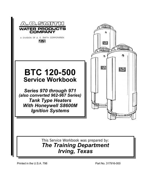
<strong>BTC</strong> <strong>120</strong>-<strong>500</strong><br />
Service Workbook<br />
Series 970 through 971<br />
(also converted 962-967 Series)<br />
Tank Type <strong>Heaters</strong><br />
With Honeywell S8600M<br />
Ignition Systems<br />
This Service Workbook was prepared by:<br />
The Training Department<br />
Irving, Texas<br />
Printed in the U.S.A. 798 Part No. 317916-000
<strong>BTC</strong> TANK TYPE HEATERS<br />
SERVICE WORKBOOK<br />
<strong>BTC</strong> WORKBOOK<br />
TABLE OF CONTENTS<br />
PAGE<br />
Troubleshooting (continued)<br />
PAGE<br />
Introduction 2-3 Wire Harness Test 31<br />
IID Module 32<br />
Installation Pilot Spark 33<br />
Clearances 3-4 Pilot Valve 34<br />
Air Requirements 5-9 Main Burner Test 35<br />
Contaminated Air 10 Flame Rectification 36<br />
Flammable 11 IID Module 37<br />
Gas Pressure 12 Main Gas Valve 38<br />
Gas Valve 13<br />
Venting 14-17 Wiring Schematics<br />
Natural and Propane Gas 39<br />
Sequence of Operation<br />
Mechanical 18 Service Charts 40-41<br />
Electrical 19-20<br />
General Questions & Answers 42<br />
Troubleshooting<br />
Transformer 21<br />
High Limit 22-23<br />
Damper (on Standby) 24 Component Part Information 50<br />
PC Board 25-26<br />
Thermostat 27 Product Information Table 51<br />
Damper (call for heat) 28-30<br />
Service Check List 52-54<br />
<strong>BTC</strong> WORKBOOK INTRODUCTION<br />
This service workbook is designed to aid in servicing and troubleshooting A.O. <strong>Smith</strong> <strong>BTC</strong> water heaters in<br />
the field. No duplication or reproduction of this book may be made without the express written authorization<br />
of the A.O. <strong>Smith</strong> <strong>Water</strong> Products Company.<br />
The following text and illustrations will provide you with a step by step procedure to verify proper installation,<br />
operation, and troubleshooting procedures. Additional quick reference data is included to assist you in<br />
servicing this product.<br />
The information contained in this workbook is designed to answer commonly faced situations encountered in<br />
the operation of the <strong>BTC</strong> product line and is not meant to be all inclusive. If you are experiencing a problem<br />
not covered in this workbook, please contact the A.O. <strong>Smith</strong> Technical Information Department at 1-800-<br />
527-1953 or your local A.O. <strong>Smith</strong> <strong>Water</strong> Products Company representative for further assistance. This<br />
workbook is intended for use by licensed plumbing professionals and reference should be made to the<br />
installation manual accompanying the product. This workbook contains supplemental information to the<br />
<strong>BTC</strong> installation and operation manual.<br />
A.O. <strong>Smith</strong> <strong>Water</strong> Products<br />
Irving, Texas ©1998<br />
1<br />
Service Workbook<br />
Training Department
<strong>BTC</strong> TANK TYPE HEATERS<br />
SERVICE WORKBOOK<br />
Qualifications: Installation or service of this water heater requires ability equivalent to that of a<br />
licensed tradesman in the field involved. Plumbing, venting and electrical testing skills are<br />
required.<br />
Tools Required:<br />
• Phillips head screw driver<br />
• standard screw drivers<br />
• a 3/8 and 7/16 inch open end wrench<br />
• set of marked drill bits<br />
• an electrical multimeter tester capable of measuring continuity<br />
• gas pressure gauge or manometer<br />
• water pressure gauge<br />
• thermometer (range 0 - 220 degree F)<br />
• 1/2 inch socket with extension for removal of the clean out cover,<br />
• 1 1/8 inch socket with extension for anode removal.<br />
A.O. <strong>Smith</strong> <strong>Water</strong> Products<br />
Irving, Texas ©1998<br />
2<br />
Service Workbook<br />
Training Department
<strong>BTC</strong> TANK TYPE HEATERS<br />
SERVICE WORKBOOK<br />
INSTALLATION<br />
This portion of the workbook will review some often overlooked installation considerations, taking<br />
note of necessary installation requirements for the <strong>BTC</strong> <strong>120</strong>-<strong>500</strong> 970 through 971 series heaters,<br />
and the <strong>BTC</strong> series 962-967 models which have been converted to Honeywell ignition systems.<br />
The installation manual covers most of these items in detail.<br />
Note: For <strong>BTC</strong> models prior to 962 series, see troubleshooting manual TC-015.<br />
FROM COMBUSTIBLES OR NON-COMBUSTIBLES AS WELL AS SERVICE<br />
<strong>BTC</strong> heaters are approved for installation on combustible flooring. Most can be installed in an<br />
alcove with minimum clearances to combustibles or non-combustibles of 6 inches from the<br />
sides and rear, 6 inches from any draft hood surface or vent piping, and 12 inches from the top<br />
cover. A 24 inch clearance for all serviceable parts is recommended. Clearances may vary<br />
between <strong>BTC</strong> models – See instruction manual or the label on the heater, for clearances<br />
applicable to your specific model.<br />
A.O. <strong>Smith</strong> <strong>Water</strong> Products<br />
Irving, Texas ©1998<br />
3<br />
Service Workbook<br />
Training Department
<strong>BTC</strong> TANK TYPE HEATERS<br />
SERVICE WORKBOOK<br />
This illustrates the exterior roof clearances for <strong>BTC</strong> units with natural draft venting. The vent shall<br />
extend at least 3 feet above the highest point where it passes through a roof of a building, and at<br />
least 2 feet higher than any portion of a building within a horizontal distance of 8 feet (for vents of<br />
12" in diameter or less). (NFPA 54 ANSI Z 223.1)<br />
"Copyright by the American Gas Association. Used by permission of the copyright holder".<br />
A.O. <strong>Smith</strong> <strong>Water</strong> Products<br />
Irving, Texas ©1998<br />
4<br />
Service Workbook<br />
Training Department
<strong>BTC</strong> TANK TYPE HEATERS<br />
SERVICE WORKBOOK<br />
Stoichiometric or theoretical complete combustion requires 10 cubic feet of air per 1000 BTUH<br />
input of the gas input. The National Fuel Gas Code also recommends an additional 2.5 cu.ft. of<br />
"excess" air. This 12.5 cu.ft minimum supply air per 1000 BTUH input applies to natural and<br />
propane gas models.<br />
The National Fuel Gas Code also specifies minimum make-up air opening sizes for various<br />
building installations. (Ref: NFPA 54, ANSI Z223.1)<br />
A.O. <strong>Smith</strong> <strong>Water</strong> Products<br />
Irving, Texas ©1998<br />
5<br />
Service Workbook<br />
Training Department
<strong>BTC</strong> TANK TYPE HEATERS<br />
SERVICE WORKBOOK<br />
A fresh supply of make-up air for combustion can be supplied to the heater through make-up air<br />
ducts which directly communicate with the out of doors. Two openings are required - one within<br />
12 inches of the top of the enclosure and one within twelve inches of the bottom of the<br />
enclosure. Each opening shall have a free area of not less than 1 square inch per 4000 BTUH of<br />
the total input of all appliances within the enclosure.<br />
The lower opening is primarily providing combustion air. The upper opening is providing vent<br />
dilution air and acts as a relief opening for flue gases should the vent become obstructed or a<br />
downdraft condition occur. Additionally, when the heater is installed in a confined space and<br />
communicating with the outdoor air, one permanent opening, commencing within 12 in. (30 cm)<br />
of the top of the enclosure, shall be permitted where the equipment has clearances of at least 1<br />
in. (2.5 cm) from the sides and back and 6 in. (16 cm) from the front of the appliance. The<br />
opening shall directly communicate with the outdoors and shall communicate through a vertical<br />
or horizontal duct to the outdoors or spaces (crawl or attic) that freely communicate with the<br />
outdoors, and shall have a minimum free area of:<br />
a. 1 sq. in. per 3000 BTU per hr (7 cm 2 per kW) of the total input of all equipment<br />
located in the enclosure, and<br />
b. Not less than the sum of the areas of all vent connectors in the confined space.<br />
A.O. <strong>Smith</strong> <strong>Water</strong> Products<br />
Irving, Texas ©1998<br />
6<br />
Service Workbook<br />
Training Department
<strong>BTC</strong> TANK TYPE HEATERS<br />
SERVICE WORKBOOK<br />
Often it is more practical to install vertical make-up air ducts to the out of doors. Again, two<br />
openings are required - one within 12 inches of the top of the enclosure and one within twelve<br />
inches of the bottom of the enclosure. Each opening shall have a free area of not less than 1<br />
square inch per 4000 BTUH of the total input of all appliances within the enclosure.<br />
A.O. <strong>Smith</strong> <strong>Water</strong> Products<br />
Irving, Texas ©1998<br />
7<br />
Service Workbook<br />
Training Department
<strong>BTC</strong> TANK TYPE HEATERS<br />
SERVICE WORKBOOK<br />
When the heater is installed in an interior room with no roof access for vertical ducts, horizontal<br />
make-up air ducts should be installed. When using horizontal ducts, two openings are required -<br />
one within 12 inches of the top of the enclosure and one within twelve inches of the bottom of the<br />
enclosure. Each opening shall have a free area of not less than 1 square inch per 2000 BTUH of<br />
the total input of all appliances within the enclosure.<br />
A.O. <strong>Smith</strong> <strong>Water</strong> Products<br />
Irving, Texas ©1998<br />
8<br />
Service Workbook<br />
Training Department
<strong>BTC</strong> TANK TYPE HEATERS<br />
SERVICE WORKBOOK<br />
Insufficient make-up air is a major cause of combustion problems. One common example is in<br />
a restaurant installation where exhaust vent equipment was not considered in sizing make-up air<br />
requirements. This may result in air being backdrafted by the restaurant exhaust equipment<br />
through the heater causing flue gas spillage, flame roll out, improper combustion, inconsistent<br />
pilot operation, and/or erratic heater shut down.<br />
A.O. <strong>Smith</strong> <strong>Water</strong> Products<br />
Irving, Texas ©1998<br />
9<br />
Service Workbook<br />
Training Department
<strong>BTC</strong> TANK TYPE HEATERS<br />
SERVICE WORKBOOK<br />
Along with adequate make-up air, the quality of the air is important. Contaminants in combustion<br />
air can lead to premature heater failure. Vapors from bleaches, soaps, waxes, salts, etc. are<br />
drawn into the combustion chamber with the make-up air and, once fired, mix with water vapor in<br />
the gases to form extremely corrosive hydrochloric or hydrofluoric acid and other corrosive<br />
byproducts.<br />
A.O. <strong>Smith</strong> <strong>Water</strong> Products<br />
Irving, Texas ©1998<br />
10<br />
Service Workbook<br />
Training Department
<strong>BTC</strong> TANK TYPE HEATERS<br />
SERVICE WORKBOOK<br />
Flammable items, pressurized containers or any other potentially hazardous articles must never<br />
be placed on or adjacent to the heater. Open containers of flammable material should not be<br />
stored or used in the same room with the heater.<br />
A.O. <strong>Smith</strong> <strong>Water</strong> Products<br />
Irving, Texas ©1998<br />
11<br />
Service Workbook<br />
Training Department
<strong>BTC</strong> TANK TYPE HEATERS<br />
SERVICE WORKBOOK<br />
The supply gas pressure is normally measured at the dirt leg or at the gas pressure tapping on<br />
the gas supply shutoff valve. This reading must be measured with 'flowing' gas.<br />
The manifold gas pressure is measured at the manifold pressure tap of the gas valve when the<br />
gas is flowing.<br />
A.O. <strong>Smith</strong> <strong>Water</strong> Products<br />
Irving, Texas ©1998<br />
12<br />
Service Workbook<br />
Training Department
<strong>BTC</strong> TANK TYPE HEATERS<br />
SERVICE WORKBOOK<br />
See page 38 for dual valve used on <strong>BTC</strong>-<strong>500</strong> models.<br />
The gas valves used on all <strong>BTC</strong> water heaters are 24 volt AC combination step opening gas<br />
valves. They incorporate the pilot valve, main valve, and gas pressure regulators into one body.<br />
The inlet view of the valve features a filter screen and pilot solenoid. On the outlet view of the<br />
gas valve, we see the pilot gas connection port, manifold gas connection port, a limited bleed<br />
vent port, and the manifold gas pressure tap.<br />
On the top view of the gas valve, we see the top knob which is a manual on/off gas control for<br />
both the pilot and main gas valves. When the top knob is placed on the black mark, gas is<br />
supplied only to the pilot valve. The pilot gas regulator is found under its cover screw. It is factory<br />
preset at 3.5"w.c. but can be adjusted from 2.5 to 5 inches water column. The main gas<br />
regulator is found under its cover screw. It is factory preset to 3.5 inches w.c. and adjusts gas<br />
pressure output from 2.5 to 5 inches water column.<br />
The two electrical terminals are marked TH and TR. The TH terminal is the common between<br />
the pilot valve solenoid coil and the main valve solenoid coil. The other wire emerging from the<br />
pilot solenoid connects to the pilot valve electrical output on the IID (terminal PV). The TR<br />
terminal connects directly to the main valve electrical output from the IID module (terminal MV).<br />
A.O. <strong>Smith</strong> <strong>Water</strong> Products<br />
Irving, Texas ©1998<br />
13<br />
Service Workbook<br />
Training Department
<strong>BTC</strong> TANK TYPE HEATERS<br />
SERVICE WORKBOOK<br />
All <strong>BTC</strong> water heaters are classified by ANSI as category I (non-condensing, negative pressure<br />
venting) appliances. They are approved for type B vent.<br />
<strong>BTC</strong>s may be common vented only with other category I appliances. (See venting section in the<br />
National Fuel Gas Code). This illustrates a single unit connected to a chimney. A minimum of<br />
1/4 inch rise per foot of the horizontal vent piping is required.<br />
A.O. <strong>Smith</strong> <strong>Water</strong> Products<br />
Irving, Texas ©1998<br />
14<br />
Service Workbook<br />
Training Department
<strong>BTC</strong> TANK TYPE HEATERS<br />
SERVICE WORKBOOK<br />
For larger applications, <strong>BTC</strong> water heaters can be common vented together either in a tapered<br />
manifold or constant size manifold. (Follow National Fuel Gas Code requirements for sizing and<br />
installation.)<br />
A.O. <strong>Smith</strong> <strong>Water</strong> Products<br />
Irving, Texas ©1998<br />
15<br />
Service Workbook<br />
Training Department
<strong>BTC</strong> TANK TYPE HEATERS<br />
SERVICE WORKBOOK<br />
SEQUENCE OF OPERATION<br />
To understand <strong>BTC</strong> tank type water heaters, an examination of their sequence of operation is<br />
necessary.<br />
When the thermostat calls for heat, the relay in the draft hood assembly activates, de-energizing<br />
the flue damper motor. The damper opens and power flows to the IID (Intermittent Ignition<br />
Device). This activates the IID module to open the pilot valve and begin sparking at the pilot<br />
burner assembly. Once the pilot flame is established and confirmed back to the IID by the flame<br />
sensor, the sparking is stopped and the main gas valve is opened, allowing gas flow to the main<br />
burner.<br />
A.O. <strong>Smith</strong> <strong>Water</strong> Products<br />
Irving, Texas ©1998<br />
18<br />
Service Workbook<br />
Training Department
<strong>BTC</strong> TANK TYPE HEATERS<br />
SERVICE WORKBOOK<br />
Honeywell Ignition Module<br />
Model S8600M<br />
CONTINUOUS RE-TRY<br />
100% SHUTOFF IP<br />
90 sec Trial - 5 min. Delay - 90 sec Retrial<br />
MV<br />
PV/MV<br />
PV<br />
GND<br />
24V (GND)<br />
24V<br />
TH-W (OPT.)<br />
SPARK<br />
B W B<br />
White<br />
Red<br />
Blue<br />
3 Wire<br />
Molex<br />
Pilot Valve<br />
White<br />
Pilot<br />
Damper<br />
White<br />
White<br />
TH TR<br />
Main Gas Valve<br />
Black<br />
Yellow<br />
<strong>120</strong> V Supply<br />
MV<br />
(Red)<br />
MV/PV (Wht)<br />
PV (Blue)<br />
L 2 L 1<br />
Neu.<br />
Hot<br />
24 Vac<br />
Transformer<br />
Hi<br />
Limit<br />
Thermostat<br />
GND<br />
Brown<br />
Honeywell Gas Valve<br />
VR8404<br />
<strong>BTC</strong>-<strong>500</strong><br />
A.O. <strong>Smith</strong> <strong>Water</strong> Products<br />
Irving, Texas ©1998<br />
19<br />
Service Workbook<br />
Training Department
<strong>BTC</strong> TANK TYPE HEATERS<br />
SERVICE WORKBOOK<br />
Electrical Sequence of Operation<br />
This wiring diagram illustrates the automatic flue damper and electronic spark ignition system on<br />
<strong>BTC</strong> commercial gas water heaters. <strong>120</strong> VAC power enters the electrical junction box on L1<br />
and L2 and is connected to a 24 VAC transformer. The neutral leg of the 24 VAC transformer is<br />
connected to the 24V (GND) on the IID and the common on the draft hood. The pilot valve<br />
solenoid and main valve solenoid are grounded to the module PV/MV terminal. The pilot is<br />
grounded to the module “GND” terminal.<br />
The hot leg of the 24 VAC transformer is connected to the IID terminal TH through the draft hood<br />
via the ECO and thermostat, powering the flue damper motor, keeping the damper closed.<br />
When the thermostat calls for heat, 24 VAC is sent through the thermostat to the draft hood,<br />
energizing the relay coil. When energized, the relay interrupts power to the flue damper motor<br />
and sends power to the end switch. A spring in the damper assembly rotates the flue damper to<br />
the open position.<br />
When fully open, the damper closes the contacts in the end switch, sending power to terminal<br />
24V of the IID, completing the circuit and activating the IID.<br />
When activated, the IID sends 24 VAC to terminal PV (energizing the normally closed pilot gas<br />
solenoid valve), and also sends a 10,000 volt spark down the ignition wire to the pilot burner.<br />
The spark ignites the pilot gas and establishes a pilot flame.<br />
The pilot flame induces a flame rectification signal, which is returned back to the IID through the<br />
igniter and ground wires, proving the pilot. When the proven pilot signal is received, the sparking<br />
is switched off and 24 VAC is sent to IID terminal MV, powering the normally closed main gas<br />
valve solenoid. The main gas valve opens and the pilot ignites the main burner.<br />
When the temperature of the water in the tank equals the temperature set on the thermostat, the<br />
contacts in the thermostat open, interrupting power, shutting down the system.<br />
A.O. <strong>Smith</strong> <strong>Water</strong> Products<br />
Irving, Texas ©1998<br />
20<br />
Service Workbook<br />
Training Department
<strong>BTC</strong> TANK TYPE HEATERS<br />
SERVICE WORKBOOK<br />
TROUBLESHOOTING <strong>BTC</strong> WATER HEATERS<br />
To troubleshoot a <strong>BTC</strong> water heater check that:<br />
• <strong>120</strong> VAC is supplied to the heater<br />
• the tank is full of water<br />
• gas is supplied to the unit<br />
STEP 1 TO TEST THE TRANSFORMER, using a multimeter, test for 24VAC between the<br />
secondary transformer terminals.<br />
- If the meter does not read 24 VAC, check the <strong>120</strong> VAC connections and retest. If<br />
still no 24 VAC, replace transformer.<br />
- If the meter reads 24 VAC, go to Step 2.<br />
A.O. <strong>Smith</strong> <strong>Water</strong> Products<br />
Irving, Texas ©1998<br />
21<br />
Service Workbook<br />
Training Department
<strong>BTC</strong> TANK TYPE HEATERS<br />
SERVICE WORKBOOK<br />
STEP 2. HIGH LIMIT, LEFT TERMINAL TEST. Test for 24 VAC between the left high limit<br />
terminal and ground.<br />
- If the meter does not read 24 VAC, check wiring between transformer and high<br />
limit.<br />
- If the meter reads 24 VAC, go to Step 3.<br />
Note: The high limit (Energy Cut Off) opens if the tank water temperature exceeds 205 degrees. The control is<br />
resettable (manually) when the tank water temperature drops below 185 degrees.<br />
A.O. <strong>Smith</strong> <strong>Water</strong> Products<br />
Irving, Texas ©1998<br />
22<br />
Service Workbook<br />
Training Department
<strong>BTC</strong> TANK TYPE HEATERS<br />
SERVICE WORKBOOK<br />
STEP 3. TO TEST HIGH LIMIT RIGHT TERMINAL , Ensure that the jumper wire between the<br />
high limit and thermostat is connected, and the damper motor power line is connected. Test for<br />
24 VAC between the high limit right terminal and ground.<br />
- If the meter does not read 24 VAC push the reset button and redo the test<br />
(storage water temperature below 185 degrees).<br />
24 VAC is now present<br />
Reasons For Resetting<br />
Condition Cause Solution<br />
High limit open Never set on initial Push high limit button<br />
installation<br />
Excessive water temperature Faulty thermostat Replace dual control<br />
Heater shut down before<br />
reaching thermostat setting<br />
Faulty high limit<br />
Replace dual control<br />
- If the meter reads 24 VAC, go to step 4.<br />
Note: The right terminal of the high limit has a jumper wire connected to the left terminal of the thermostat.<br />
There is also a black wire connecting to the damper motor assembly. This black wire supplies power to the<br />
motor to close the damper during periods of standby.<br />
A.O. <strong>Smith</strong> <strong>Water</strong> Products<br />
Irving, Texas ©1998<br />
23<br />
Service Workbook<br />
Training Department
<strong>BTC</strong> TANK TYPE HEATERS<br />
SERVICE WORKBOOK<br />
STEP 4. INSPECT THE DAMPER. Lower the thermostat setting so the unit will not be calling<br />
for heat, then inspect the damper.<br />
- If the damper is open, go to step 5.<br />
- If the damper is closed, go to step 7.<br />
Note: If the water temperature in the tank is below <strong>120</strong> degrees F, disconnect the jumper wire between the<br />
high limit and thermostat to simulate a satisfied thermostat.<br />
A.O. <strong>Smith</strong> <strong>Water</strong> Products<br />
Irving, Texas ©1998<br />
24<br />
Service Workbook<br />
Training Department
<strong>BTC</strong> TANK TYPE HEATERS<br />
SERVICE WORKBOOK<br />
STEP 5. CHECK THE PC BOARD. Test for 24 VAC between the black PC board wire<br />
connection and ground.<br />
- If 24 VAC is not present, check the black wire connections between the PC board<br />
and high limit.<br />
- If 24 VAC is present, go to Step 6.<br />
Momentary Push<br />
Button<br />
A.O. <strong>Smith</strong> <strong>Water</strong> Products<br />
Irving, Texas ©1998<br />
25<br />
Motor Lead<br />
Terminals<br />
Service Workbook<br />
Training Department
<strong>BTC</strong> TANK TYPE HEATERS<br />
SERVICE WORKBOOK<br />
STEP 6. PC BOARD/MOTOR TEST. Check for 24 VAC between the two motor lead terminals<br />
of the PC board. Disconnected the wires for this test.<br />
- If 24 VAC is not present, replace the board (<strong>AO</strong>S Part # 6522) and go to step 7.<br />
The board and relay are one piece. Regardless of which part is defective, both<br />
parts would be changed.<br />
- If voltage is present, this verifies that the motor is receiving power but not closing<br />
the damper. Replace the motor (<strong>AO</strong>S Part # 6521) and go to step 7.<br />
Note: The "momentary push button" service switch may be used to provide single heating cycles, while<br />
waiting for a replacement part.<br />
WARNING - In the event of damper motor failure, verify that the damper is in the "open" position before<br />
utilizing the momentary push button service switch.<br />
A.O. <strong>Smith</strong> <strong>Water</strong> Products<br />
Irving, Texas ©1998<br />
26<br />
Service Workbook<br />
Training Department
<strong>BTC</strong> TANK TYPE HEATERS<br />
SERVICE WORKBOOK<br />
STEP 7. THERMOSTAT TEST. Set the thermostat to call for heat. Using your multimeter,<br />
test for 24 VAC between right terminal and ground.<br />
- If the meter does not read 24 VAC and the jumper wire between the high limit and<br />
the thermostat is in place, replace the thermostat.<br />
- If the meter reads 24 VAC, go to Step 8.<br />
Note: If the high limit to thermostat jumper wire was disconnected earlier to simulate a satisfied thermostat,<br />
reconnect the jumper to the terminals.<br />
Note: A yellow wire from this thermostat terminal connects to the damper PC board.<br />
A.O. <strong>Smith</strong> <strong>Water</strong> Products<br />
Irving, Texas ©1998<br />
27<br />
Service Workbook<br />
Training Department
<strong>BTC</strong> TANK TYPE HEATERS<br />
SERVICE WORKBOOK<br />
STEP 8. DAMPER INPUT TEST. Test for 24 VAC between the yellow wire on the PC board<br />
and ground.<br />
- If the meter does not read 24 VAC and you have checked the wire and plug<br />
connections, then replace the wiring harness.<br />
- If the meter does read 24 VAC, go to Step 9.<br />
A.O. <strong>Smith</strong> <strong>Water</strong> Products<br />
Irving, Texas ©1998<br />
28<br />
Service Workbook<br />
Training Department
<strong>BTC</strong> TANK TYPE HEATERS<br />
SERVICE WORKBOOK<br />
STEP 9. TO TEST THE DAMPER, visually check the damper blade position.<br />
- If the damper does NOT open fully, replace the damper assembly.<br />
- If the damper DOES open fully, go to step 10.<br />
A.O. <strong>Smith</strong> <strong>Water</strong> Products<br />
Irving, Texas ©1998<br />
29<br />
Service Workbook<br />
Training Department
<strong>BTC</strong> TANK TYPE HEATERS<br />
SERVICE WORKBOOK<br />
STEP 10. TO TEST DAMPER OUTPUT - on a call for heat. The damper receives power<br />
through the yellow wire, the damper opens and proves it is open via an end switch before power<br />
flows through the red wire from the PC board.<br />
Place the red test probe on the solder joint of the red wire connection to the damper PC board.<br />
- If the meter does not read 24 VAC, replace the PC board.<br />
- If the meter reads 24 VAC, go to step 11.<br />
Note: The spring rotates the damper blade assembly to the open position. This closes an end switch.<br />
A.O. <strong>Smith</strong> <strong>Water</strong> Products<br />
Irving, Texas ©1998<br />
30<br />
Service Workbook<br />
Training Department
<strong>BTC</strong> TANK TYPE HEATERS<br />
SERVICE WORKBOOK<br />
STEP 11. WIRE HARNESS TEST. Test for 24 VAC between terminal 24V on the IID module,<br />
and 24V (GND).<br />
- If 24 VAC is not present, check the wiring harness.<br />
- If 24 VAC is present, reconnect the red wire to terminal 24V on the IID module and<br />
go to Step 12.<br />
Note: This test may be easier to conduct by removing the red wire from the IID terminal. Test for 24 VAC<br />
between the red wire and ground. Reconnect the red wire to the 24V terminal after the test.<br />
A.O. <strong>Smith</strong> <strong>Water</strong> Products<br />
Irving, Texas ©1998<br />
31<br />
Service Workbook<br />
Training Department
<strong>BTC</strong> TANK TYPE HEATERS<br />
SERVICE WORKBOOK<br />
STEP 12. IID MODULE TEST. Using a multimeter, test for 24 VAC between terminal PV and<br />
24V (GND) on the IID during the 90 second trial for ignition.<br />
- If the meter does not read 24 VAC and the IID module is not between ignition<br />
trials, then replace the module.<br />
- If the meter does read 24 VAC, go to Step 13.<br />
A.O. <strong>Smith</strong> <strong>Water</strong> Products<br />
Irving, Texas ©1998<br />
32<br />
Service Workbook<br />
Training Department
<strong>BTC</strong> TANK TYPE HEATERS<br />
SERVICE WORKBOOK<br />
STEP 13. PILOT SPARK TEST. Visually check for spark at the pilot assembly.<br />
Note: The pilot burner mounts on the left side of the main burner on 970/971 series heaters.<br />
If the igniter is not sparking, check for:<br />
• a 7/64" spark gap<br />
• spark cable continuity<br />
• ground cable continuity<br />
Adjust or replace as needed.<br />
If sparking is present, go to Step 14.<br />
Power To Module Must Be Interrupted To Reset .<br />
Trial for Ignition<br />
90 sec. 5 min. 90 sec. 5 min. 90 sec.<br />
Call for heat Sparking No Sparking Sparking No Sparking Sparking<br />
Continuous<br />
Trial<br />
Sequence<br />
A.O. <strong>Smith</strong> <strong>Water</strong> Products<br />
Irving, Texas ©1998<br />
33<br />
Service Workbook<br />
Training Department
<strong>BTC</strong> TANK TYPE HEATERS<br />
SERVICE WORKBOOK<br />
STEP 14. PILOT VALVE - OHM TEST. If pilot assembly is sparking but no pilot flame is<br />
established, disconnect the pilot valve solenoid leads. Using a multimeter, (set to read ohms)<br />
test for 20* ohms resistance +/- 5 through the solenoid coil.<br />
- If the meter does not read 20 ohms plus or minus 5, replace gas valve.<br />
- If the meter does read 20 ohms plus or minus 5, check for:<br />
• pilot gas - if none, replace gas valve.<br />
• blockage in pilot tube or orifice - clear blockage and go on to Step 15.<br />
*<strong>BTC</strong> <strong>500</strong> - Honeywell Dual Valve check that coil is not open between blue (PV) and white<br />
(MV/PV) terminals.<br />
A.O. <strong>Smith</strong> <strong>Water</strong> Products<br />
Irving, Texas ©1998<br />
34<br />
Service Workbook<br />
Training Department
<strong>BTC</strong> TANK TYPE HEATERS<br />
SERVICE WORKBOOK<br />
STEP 15. MAIN BURNER TEST. Visually check for main burner.<br />
- If the main burner ignites, sequence is complete.<br />
- If the main burner does not ignite, go to Step 16.<br />
A.O. <strong>Smith</strong> <strong>Water</strong> Products<br />
Irving, Texas ©1998<br />
35<br />
Service Workbook<br />
Training Department
<strong>BTC</strong> TANK TYPE HEATERS<br />
SERVICE WORKBOOK<br />
STEP 16. FLAME RECTIFICATION<br />
Note: Flame rectification means that an alternating current (AC) signal is changed to a direct current (DC)<br />
signal. The pilot flame is the 'switch' which connects the pilot hood to the igniter and ground. If the pilot<br />
hood and igniter sensor had the same surface area, the flame 'switch' would conduct an AC signal.<br />
Because the pilot surface is greater than the igniter surface, the signal becomes a DC current that the<br />
module can interpret. The pilot hood must be properly grounded and the pilot flame must remain in contact<br />
with both surfaces for the flame proving signal to remain constant.<br />
If the signal is broken for just 8 tenths of a second, the heater will cycle off.<br />
Sparking at the pilot will continue if an insufficient signal is received by the module.<br />
Sparking at the pilot will stop almost immediately after the ignition module senses the pilot flame.<br />
A.O. <strong>Smith</strong> <strong>Water</strong> Products<br />
Irving, Texas ©1998<br />
36<br />
Service Workbook<br />
Training Department
<strong>BTC</strong> TANK TYPE HEATERS<br />
SERVICE WORKBOOK<br />
Pilot is lit - Sparking has stopped.<br />
STEP 17. IID MODULE TEST. Using a multimeter, test for 24 VAC between terminal MV on<br />
the IID and 24V (GND).<br />
- If 24 VAC is not present, replace the IID module. Conduct Step 18 before applying<br />
power to replacement module.<br />
- If 24 VAC is present, go to Step 18.<br />
A.O. <strong>Smith</strong> <strong>Water</strong> Products<br />
Irving, Texas ©1998<br />
37<br />
Service Workbook<br />
Training Department
<strong>BTC</strong> TANK TYPE HEATERS<br />
SERVICE WORKBOOK<br />
STEP 18. MAIN GAS VALVE CHECK. Disconnect wires from gas valve TH and TR terminals.<br />
Using a multimeter, test for 68 ohms plus or minus 5 between TH and TR on the main valve<br />
coil.<br />
- If the meter reads 'O' or infinity, replace the gas valve.<br />
- If the meter reads 68* ohms plus or minus 5, the main burner will ignite.<br />
-<br />
*<strong>BTC</strong> <strong>500</strong> - Honeywell Dual Valve = Check that coil is not open between red (MV) and white<br />
(MV/PV) terminals.<br />
ALTERNATE <strong>BTC</strong>-<strong>500</strong> GAS VALVE<br />
A.O. <strong>Smith</strong> <strong>Water</strong> Products<br />
Irving, Texas ©1998<br />
38<br />
Service Workbook<br />
Training Department
<strong>BTC</strong> TANK TYPE HEATERS<br />
SERVICE WORKBOOK<br />
<strong>BTC</strong> WIRING DIAGRAM - NATURAL AND PROPANE GAS<br />
Honeywell Ignition System<br />
IF ANY OF THE ORIGINAL WIRE AS SUPPLIED MUST BE REPLACED, USE<br />
ONLY TYPE 105° C THERMOPLASTIC OR EQUIVALENT.<br />
MV<br />
(Red)<br />
MV/PV (Wht)<br />
PV (Blue)<br />
Honeywell Gas<br />
Valve VR8404<br />
<strong>BTC</strong>-<strong>500</strong><br />
A.O. <strong>Smith</strong> <strong>Water</strong> Products<br />
Irving, Texas ©1998<br />
39<br />
Service Workbook<br />
Training Department
<strong>BTC</strong> TANK TYPE HEATERS<br />
SERVICE WORKBOOK<br />
GENERAL SERVICE CHART<br />
CONDITION CAUSE SOLUTION<br />
PILOT LIGHTS, SPARK<br />
CONTINUOUSLY<br />
PILOT FLAME NOT<br />
PROVING<br />
SEE FLAME RECTIFICATION - STEP<br />
16<br />
HEATER WILL NOT<br />
IGNITE<br />
NOT PROVING PILOT<br />
FLAME EXISTANCE<br />
INTERRUPT <strong>120</strong> VAC POWER<br />
. CHECK GROUND WIRE<br />
ATTACHMENT<br />
. CLEAN OR REPLACE PILOT<br />
ASSEMBLY<br />
WEEPING<br />
TEMPERATURE AND<br />
PRESSURE RELIEF<br />
VALVE<br />
PREMATURE TANK<br />
LEAKAGE<br />
PILOT GAS NOT<br />
COMPLETELY<br />
INTERRUPTED AT END OF<br />
HEATING CYCLE<br />
THERMAL EXPANSION<br />
CONDENSATION<br />
CONTAMINATED AIR<br />
WATER HAMMER<br />
THERMAL EXPANSION<br />
. CHECK SUPPLY GAS PRESSURE<br />
. REPLACE GAS VALVE<br />
ADD THERMAL EXPANSION TANK<br />
. INCREASE STORED WATER<br />
TEMPERATURE AND CONFIRM<br />
PROPERLY SIZED APPLICATION<br />
. REMOVE CONTAMINANTS.<br />
. SUPPLY CLEAN COMBUSTION<br />
AIR.<br />
. ADD WATER HAMMER<br />
ARRESTOR.<br />
. REDUCE WATER PRESSURE.<br />
. REMOVE UNNECESSARY CHECK<br />
VALVES.<br />
ADD THERMAL EXPANSION TANK.<br />
DEPLETED ANODES SCHEDULE ANODE CHECKS -<br />
REPLACE AS NEEDED.<br />
GENERAL SERVICE CHART (continued)<br />
A.O. <strong>Smith</strong> <strong>Water</strong> Products<br />
Irving, Texas ©1998<br />
40<br />
Service Workbook<br />
Training Department
<strong>BTC</strong> TANK TYPE HEATERS<br />
SERVICE WORKBOOK<br />
CONDITION CAUSE SOLUTION<br />
DAMPER WILL NOT BINDING SHAFT<br />
SUPPORT VENTING<br />
OPEN<br />
SHAFT SPRING<br />
REPLACE DAMPER<br />
WEAK/BROKEN<br />
DAMPER MOTOR<br />
REPLACE MOTOR<br />
NO SPARK AT PILOT -<br />
DAMPER FULLY OPEN<br />
DAMPER ASSEMBLY REPLACE PC BOARD - SEE STEP 10<br />
Pushing momentary services button may<br />
provide a tank of hot water.<br />
IID MODULE REPLACE IID STEP 12<br />
SPARK CABLE REPLACE CABLE STEP 13<br />
A.O. <strong>Smith</strong> <strong>Water</strong> Products<br />
Irving, Texas ©1998<br />
41<br />
Service Workbook<br />
Training Department
<strong>BTC</strong> TANK TYPE HEATERS<br />
SERVICE WORKBOOK<br />
GENERAL QUESTIONS AND ANSWERS<br />
Q: How much electrical power is required for a <strong>BTC</strong> water heater?<br />
A: The <strong>BTC</strong> models draw approximately .7 Amps.<br />
Q: The units require "leg kits" to meet National Sanitation Foundation standards.<br />
What are the model numbers for these kits?<br />
A: The <strong>BTC</strong> model heaters with 28 inch diameter tanks (<strong>BTC</strong> 198, 200, 250, 275 and<br />
400) need <strong>AO</strong>S kit number 192293 "leg extension kit".<br />
A: The <strong>BTC</strong> model heaters; with 24 inch diameter tanks (all others) need <strong>AO</strong>S kit<br />
number 6569. This kit consists of pt. no. 191037 "vermin guard" and pt. no. 97059-<br />
1 "leg cover".<br />
Q: When should <strong>BTC</strong>s be delimed?<br />
Many variables affect the liming up process including:<br />
water temperature - The amount of lime accumulation during the same period of<br />
time will be nearly 4 times greater if water is stored at 140 degrees F than at <strong>120</strong><br />
degrees F. a 180 degree setting will build up lime twice as fast as a 140 degree F<br />
setting.<br />
volume of water - The more gallons flowing through the <strong>BTC</strong>, the more rapid the<br />
accumulation.<br />
hardness – the harder the water the quicker lime build up occurs. 1 to 3.5 grains<br />
per gallon is "soft", 3.5 to 7 grains per gallon is "moderate", 7 to 10.5 grains per<br />
gallon is "hard" and 10.5 + grains per gallon is "very hard". (An aspirin is about 5<br />
grains. One grain is equal to 17.1 parts per million.)<br />
A: Deliming should be done when a slight rumbling or popping sound is detected when<br />
the main burners are on.<br />
Q: What effect will lime build-up have on the <strong>BTC</strong> water heater?<br />
A: One eighth inch of scale build-up may reduce efficiency as much as 22%; a 1/4<br />
inch build-up, as much as 38%.<br />
A: Less efficient heat transfer means more bottom head expansion/contraction stress<br />
and premature leakage.<br />
A: Heavy build-up on the bottom head and bottom portion of the flue pipes leads to<br />
more heat transfer at the top of the flues. This can lead to stacking or erratic<br />
thermostat operation.<br />
Q: Anode rods provide additional protection against corrosion. When should these be<br />
replaced?<br />
A: When large gouges or pits appear in the anodes, replace them.<br />
Q: How often should these anodes be inspected?<br />
A: Approximately every six months.<br />
A.O. <strong>Smith</strong> <strong>Water</strong> Products<br />
Irving, Texas ©1998<br />
42<br />
Service Workbook<br />
Training Department
<strong>BTC</strong> TANK TYPE HEATERS<br />
SERVICE WORKBOOK<br />
COMPONENT PART INFORMATION<br />
NAME<br />
SPECIFICATIONS<br />
DUAL<br />
CONTROLLER<br />
THERMOSTAT<br />
HIGH LIMIT<br />
(ECO)<br />
<strong>120</strong>-180 O RANGE, + 4 O , 5 O<br />
DIFFERENTIAL,<br />
LIQUID FILLED, ANTI-<br />
STACKING<br />
OPENS - 205 O FIXED,<br />
MANUAL<br />
RESET BELOW 185 O<br />
GAS VALVE NATURAL GAS <strong>BTC</strong> <strong>120</strong> THRU 250, 275<br />
THRU 400 24 VAC, 60<br />
HZ, .6A; .7 TO 3.5" W.C. STEP<br />
<strong>BTC</strong>-400; 24 VAC, 60 HZ, .6A;<br />
.8 TO 3.5" W.C. STEP<br />
<strong>BTC</strong>-<strong>500</strong>; 24 VAC, 60 HZ, .7A;<br />
STEP OPENING<br />
INTERMITENT<br />
IGNITION DEVICE<br />
CONTROL<br />
DAMPER<br />
TRANSFORMER<br />
PROPANE GAS<br />
NATURAL GAS<br />
AND PROPANE<br />
GAS<br />
<strong>BTC</strong> <strong>120</strong> THRU 400; 24 VAC,<br />
60 HZ,<br />
.6A 2.5 TO 10" W.C. STEP<br />
<strong>BTC</strong> <strong>500</strong>; 24 VAC, 60 HZ, .7A;<br />
STEP OPENING<br />
24 VAC, 50-60 HZ, .1A;<br />
.7 MICROAMP SIGNAL<br />
CONTINUOUS RETRIAL<br />
COMPLETE<br />
ASSEMBLY<br />
MOTOR 24 VAC, 60 HZ, <strong>120</strong> RPM, 5<br />
WATT<br />
P.C. BOARD<br />
W/RELAY<br />
MOMENTARY PUSH BUTTON<br />
<strong>120</strong> V PRIMARY, 24 VAC<br />
SECONDARY,<br />
40 VA, 50-60 HZ, CLASS 2 "B"<br />
A.O. <strong>Smith</strong> <strong>Water</strong> Products<br />
Irving, Texas ©1998<br />
50<br />
Service Workbook<br />
Training Department
A.O. <strong>Smith</strong> <strong>Water</strong> Products Co. 51 Service Workbook<br />
Irving, Texas ©1998 Training Department<br />
<strong>BTC</strong><br />
MODEL<br />
<strong>120</strong><br />
154<br />
179<br />
197<br />
199<br />
200<br />
240<br />
250<br />
251<br />
275<br />
305<br />
365<br />
400<br />
<strong>500</strong><br />
INLET WATER<br />
CONNECTIONS<br />
PRODUCT INFORMATION TABLE<br />
OUTLET WATER<br />
CONNECTIONS<br />
TANK CONSTRUCTION<br />
AVAILABLE<br />
AVAILABLE<br />
Top Front Rear Top Front Rear Standard ASME Nat.Gas Prop.Gas<br />
X<br />
X<br />
X<br />
X<br />
X<br />
X<br />
X<br />
X<br />
X<br />
X<br />
X<br />
X<br />
X<br />
X<br />
ALL REQUIRE LEG KITS TO MEET NSF REQUIREMENTS.<br />
X<br />
X<br />
X<br />
X<br />
X<br />
X<br />
X<br />
X<br />
X<br />
X<br />
X<br />
X<br />
X<br />
X<br />
X<br />
X<br />
X<br />
X<br />
X<br />
X<br />
X<br />
X<br />
X<br />
X<br />
X<br />
X<br />
X<br />
X<br />
X<br />
X<br />
X<br />
X<br />
X<br />
X<br />
X<br />
X<br />
X<br />
X<br />
X<br />
X<br />
X<br />
X<br />
X<br />
X<br />
X<br />
X<br />
X<br />
X<br />
X<br />
X<br />
X<br />
X<br />
X<br />
X<br />
X<br />
X<br />
X<br />
X<br />
X<br />
X<br />
X<br />
X<br />
X<br />
X<br />
235,000<br />
X<br />
X<br />
X<br />
480,000<br />
<strong>BTC</strong> TANK TYPE HEATERS<br />
SERVICE WORKBOOK
<strong>BTC</strong> TANK TYPE HEATERS<br />
SERVICE WORKBOOK<br />
<strong>BTC</strong> SERVICE CHECKLIST<br />
This checklist is intended to aid the Service Agent in determining that the A.O. <strong>Smith</strong> <strong>BTC</strong> <strong>Water</strong><br />
Heater has been properly installed and is operating correctly. Because the circumstances of each<br />
installation may vary greatly, it is not intended to be an all-inclusive list of the problems that the<br />
Service Agent may encounter. Any item checked "no" on this list should be thoroughly<br />
investigated and corrective action taken, if required.<br />
SERVICE AGENT<br />
MODEL NUMBER<br />
SERIAL NUMBER<br />
INSTALLATION DATE<br />
SERVICE DATE<br />
LOCATION ADDRESS<br />
GAS TYPE - CHECK ONE<br />
NATURAL PHONE ( ) -<br />
PROPANE<br />
I. Check Clearances (circle answer)<br />
A. Are exterior clearances adequate yes no<br />
B. Are interior clearances adequate yes no<br />
Comments:<br />
II.<br />
Check Makeup Air Requirements<br />
A. Is the quantity of make-up air adequate? yes no<br />
Comments:<br />
B. Is the quality of make-up air adequate? yes no<br />
Comments:<br />
III.<br />
Gas Pressure (fill in blank)<br />
A. Supply gas pressure inches of w.c.<br />
B. Manifold gas pressure (main burner) inches of w.c.<br />
Comments:<br />
IV.<br />
Venting (check)<br />
A. Adequately sized yes no<br />
B. Does the installation have mechanically assisted venting: yes no<br />
If so, is it operational: yes no<br />
Comments:<br />
(This service checklist may be photo copied to assist with <strong>BTC</strong> service call.)<br />
A.O. <strong>Smith</strong> <strong>Water</strong> Products<br />
Irving, Texas ©1998<br />
52<br />
Service Workbook<br />
Training Department
<strong>BTC</strong> TANK TYPE HEATERS<br />
SERVICE WORKBOOK<br />
V. WATER PIPING<br />
Is the system properly sized? yes no<br />
Is the system properly installed? yes no<br />
Are there any water leaks? yes no<br />
Does the installation have a recirculating system? yes no<br />
If so, is it operational? yes no<br />
VI.<br />
PROPER SEQUENCE OF OPERATION<br />
During standby does damper close on standby? yes no<br />
During standby is pilot flame off? yes no<br />
On a call for heat does thermostat close? yes no<br />
On a call for heat does damper open completely? yes no<br />
Does sparking begin at pilot? yes no<br />
Is pilot flame established? yes no<br />
If so, does sparking stop? yes no<br />
Does main burner ignite? yes no<br />
Does the thermostat satisfy? yes no<br />
Does damper close? yes no<br />
Comments:<br />
VII.<br />
SAFETY<br />
A. Gas<br />
Does pilot flame prove before main burner ignites? yes no<br />
Does damper blade fully open before ignition sequence occurs? yes no<br />
Is burner cover plate in place? yes no<br />
Is burner floor shield in place? yes no<br />
Does IID lockout occur after 30 sec. trial for ignition? (Propane models only) yes no<br />
B. <strong>Water</strong> Temperature<br />
Is the thermostat adjusted to the lowest acceptable temperature? yes no<br />
Does the installation have a mixing valve? yes no<br />
If so, is it operational? yes no<br />
What is the outlet temperature of the mixing valve?<br />
NOTE: (To minimize the risk of scalding, the manufacturer recommends storing water at <strong>120</strong>°F.)<br />
Is a properly rated temperature and pressure relief valve installed? yes no<br />
C. Electrical<br />
Is the <strong>120</strong> VAC electrical power supply properly wired? yes no<br />
Are all the <strong>BTC</strong> control covers in place? yes no<br />
Is the <strong>120</strong> VAC electrical power supply properly fused? yes no<br />
D. Flammables<br />
Are flammable materials located in the area of the water heater? yes no<br />
Are flammable vapors located in the area of the water heater? yes no<br />
Comments:<br />
(This service checklist may be photo copied to assist with <strong>BTC</strong> service call.)<br />
A.O. <strong>Smith</strong> <strong>Water</strong> Products<br />
Irving, Texas ©1998<br />
53<br />
Service Workbook<br />
Training Department
<strong>BTC</strong> TANK TYPE HEATERS<br />
SERVICE WORKBOOK<br />
COMMENTS<br />
[This service checklist may be photo copied to assist with <strong>BTC</strong> service calls].<br />
A.O. <strong>Smith</strong> <strong>Water</strong> Products<br />
Irving, Texas ©1997<br />
54<br />
Service Workbook<br />
Training Department


