Site Master S331D_S332D
Site Master S331D_S332D
Site Master S331D_S332D

You also want an ePaper? Increase the reach of your titles
YUMPU automatically turns print PDFs into web optimized ePapers that Google loves.
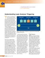
<strong>Site</strong> <strong>Master</strong> <br />
Cable and Antenna Analyzer<br />
25 MHz to 4000 MHz<br />
<strong>S331D</strong>/<strong>S332D</strong><br />
<strong>Site</strong><strong>Master</strong><br />
The World’s Leading Cable and Antenna System Analyzer
<strong>Site</strong> <strong>Master</strong> is the Preferred Cable and Antenna Analyzer<br />
of Wireless Service Providers, Contractors, and Installers.<br />
Cost Savings and Quality Improvement<br />
Wireless market competition requires operators to reduce per site maintenance<br />
expense. <strong>Site</strong> <strong>Master</strong>’s Frequency Domain Reflectometry (FDR) techniques break<br />
away from the traditional fix-after-failure maintenance process by finding small, hard<br />
to identify problems before major failures occur.<br />
Sixty to eighty percent of a typical cell site’s problems are caused by problematic<br />
cables, connectors and antennas. When cables or antennas are contaminated with<br />
moisture, damaged, or mispositioned during storms, <strong>Site</strong> <strong>Master</strong> identifies the<br />
problem quickly. Antenna degradation reduces the cell coverage pattern and can<br />
cause dropped calls. <strong>Site</strong> <strong>Master</strong> can pinpoint the antenna problem from ground<br />
level in a few seconds making climbing the antenna tower unnecessary.<br />
A poorly installed weather seal will corrode connectors and, if undetected, will<br />
eventually damage an expensive coaxial cable. <strong>Site</strong> <strong>Master</strong> has the sensitivity to<br />
identify the connector problem before the cable is damaged. Distance-To-Fault<br />
provides the clearest indication of troubled areas.<br />
<strong>Site</strong> <strong>Master</strong><br />
Revolutionizes<br />
Cable and<br />
Antenna<br />
Sweeping<br />
in the Wireless<br />
Industry.<br />
Rugged and Reliable<br />
Because the <strong>Site</strong> <strong>Master</strong> was designed specifically for field environments, it<br />
can easily withstand the day-to-day punishment of field use. The analyzer is<br />
almost impervious to the bumps and bangs typically encountered by portable<br />
field-equipment.<br />
Easy-to-Use<br />
<strong>Site</strong> <strong>Master</strong> operation is straightforward; measurements are obtained<br />
through a menu-driven user interface that is easy to use and requires little<br />
training. The large, and high-resolution TFT color display makes test<br />
interpretation easy and quick. A full range of markers enable the user to<br />
make accurate measurements. Limit lines simplify measurements allowing<br />
users to create quick and simple pass/fail tests.<br />
Features local language graphical user interface support in<br />
English, Chinese, Japanese, French, German, and Spanish.<br />
2
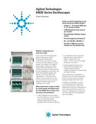
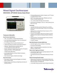
RS-232 Interface<br />
Transfer stored data to and from<br />
a personal computer (PC) or<br />
download to a printer via a serial<br />
cable for further analysis. Use PC<br />
to automatically control and collect<br />
data in the field.<br />
External DC<br />
Power Port<br />
Spectrum Analyzer<br />
and Power Meter Port<br />
External Trigger and<br />
External Reference In<br />
Cable and Antenna<br />
Analyzer Port<br />
T1/E1 Receive and Transmit Port<br />
<strong>S331D</strong> Models with Option 50.<br />
Snap-in Field replaceable<br />
battery location<br />
Frequency Converter Module Port<br />
Option 6 (<strong>S332D</strong>) for control of an<br />
external frequency extension module.<br />
Rugged and Reliable<br />
Chassis Design<br />
Ruggedized, lightweight,<br />
compact, high-impact housing is<br />
designed to withstand repeated<br />
drops and rough handling.<br />
Weather resistant seals and<br />
rubber membrane keypad<br />
protect unit from dirt and<br />
moisture.<br />
Save and Recall Setup<br />
Save setups for fast<br />
repeatable testing:<br />
<strong>S332D</strong> Models - 20<br />
<strong>S331D</strong> Models - 25<br />
Markers<br />
Six markers for more<br />
comprehensive measurements.<br />
Limits<br />
Create simple pass/fail<br />
measurements with a single limit<br />
line, upper and/or lower mask<br />
limit lines.<br />
TFT Color Display<br />
Standard TFT (640 x 480) color<br />
display featuring variable<br />
brightness control.<br />
Viewable in direct sunlight.<br />
Multilingual User Interface<br />
Multi-language user interface<br />
features on-screen menus and<br />
messages in six different<br />
languages: Chinese, English,<br />
French, German, Japanese,<br />
Spanish.<br />
Function Keys<br />
Four dedicated function keys simplify<br />
measurement tasks.<br />
Soft Keys<br />
Intuitive soft key menu<br />
and user interface.<br />
Save and Recall Display<br />
Up to 200 memory locations.<br />
Alphanumeric data labeling<br />
and automatic time/date stamp<br />
simplify data management.<br />
AM/FM Receiver<br />
with Internal Speaker<br />
Built-in AM/FM demodulator<br />
enables testing and troubleshooting<br />
of wireless<br />
communications systems.<br />
An internal speaker and jack are<br />
included.<br />
Function<br />
Cable and Antenna Analyzer (331D/<strong>S332D</strong>)<br />
Spectrum Analyzer (<strong>S332D</strong>)<br />
AM/FM Demodulator (<strong>S332D</strong>)<br />
Benefits<br />
Characterize antenna system and pinpoint location of faults<br />
Easily locate, identify and record various signals with high accuracy<br />
Built-in demodulator for AM, narrow band FM, wide band FM, and SSB allows technician to<br />
listen to and identify interfering signals<br />
Standard TFT Color Display (<strong>S331D</strong>/<strong>S332D</strong>) Display is viewable in direct sunlight<br />
Power Monitor (<strong>S331D</strong>/<strong>S332D</strong>)<br />
Performs accurate broadband power measurements using an external detector<br />
Frequency Converter Interface (<strong>S332D</strong>) Make measurement from 4.7 to 6 GHz using an external detector<br />
Built-in +12 to +24V variable Bias Tee (<strong>S332D</strong>) No need to use external power to bias an amplifier<br />
Transmission Measurement (<strong>S332D</strong>)<br />
Identify and locate interfering signals that cause dropped calls and coverage problems.<br />
Intermittent problems can be identified using spectrograms<br />
Interference Analyzer (<strong>S332D</strong>)<br />
Identify and locate interfering signals that cause dropped calls and coverage problems.<br />
Intermittent problems can be identified using spectrograms<br />
Channel Scanner (<strong>S332D</strong>)<br />
CW Signal Generator (<strong>S332D</strong>)<br />
Power Meter (<strong>S331D</strong>/<strong>S332D</strong>)<br />
GPS Receiver (<strong>S331D</strong>/<strong>S332D</strong>)<br />
T1/E1 Analyzer (<strong>S331D</strong>)<br />
Measure frequency, bandwidth and power of multiple transmitted signals<br />
CW source to test low noise amplifiers<br />
Performs accurate power measurements up to 3 GHz without the need of an external detector<br />
Provides location (latitude, longitude, altitude) and UTC time information<br />
Simplifies the task of determining if the source of problems is on the wireline or the wireless side<br />
3
Cable and Antenna Analysis – Increase System Uptime<br />
FDR Technique<br />
Frequency Domain Reflectometry, (FDR), and Time Domain Reflectometry, (TDR), have similar acronyms, and both<br />
techniques are used to test transmission lines. But, that’s where the similarities end. TDRs are not sensitive to RF problems:<br />
the TDR stimulus is a DC pulse, not RF. Thus, TDRs are unable to detect system faults that often lead to system failures.<br />
Additionally, FDR techniques save costly, time-consuming trouble shooting efforts by testing cable feed-line and antenna<br />
systems at their proper operating frequency.<br />
Deficient connectors, lightning arrestors, cables, jumpers, or antennas are replaced before call quality is compromised.<br />
Quick, Simple Measurements<br />
<strong>Site</strong> <strong>Master</strong> performs various RF measurements aimed at simplifying cable feedline and antenna analysis: Return Loss,<br />
SWR, Cable Loss and Distance-to-Fault (DTF). A single key selection on the main menu activates the desired measurement<br />
mode.<br />
Return Loss, SWR<br />
Return Loss and SWR “system" measurements ensure conformance to<br />
system performance engineering specifications. Measurement easily toggles<br />
between either one of the two modes and can be performed without climbing<br />
the tower.<br />
Cable Loss<br />
Cable Loss measurements measure the level of insertion loss within the cable<br />
feed-line system. Insertion loss can be verified prior to deployment, when you<br />
have access to both ends of the cable, or on installed cables without access to<br />
the opposite end. <strong>Site</strong> <strong>Master</strong> automatically calculates and displays the average<br />
cable loss so there is no more guess work or a need to perform calculations in<br />
the field.<br />
4<br />
Distance-to-Fault<br />
Although a Return Loss test can tell users the magnitude of signal reflections,<br />
it cannot tell the precise location of a fault within the feed-line system.<br />
Distance-To-Fault measurements provide the clearest indication of trouble<br />
areas as it tells us both the magnitude of signal reflection and the location of<br />
the signal anomaly.<br />
Distance-To-Fault measurement capability is built into all <strong>Site</strong> <strong>Master</strong> models as<br />
a standard feature. Return Loss (SWR) measurement data is processed using<br />
Fast Fourier Transform and the resulting data indicates Return Loss (SWR)<br />
versus distance. Distance-to-Fault measurements indicating Return Loss or<br />
SWR versus time is available with Handheld Software Tools .
OSL Calibration<br />
Open-Short-Load (OSL) calibration is standard for the <strong>S331D</strong> and <strong>S332D</strong>. All errors from source match, directivity and<br />
frequency response are mathematically removed allowing for accurate vector corrected Return Loss, Cable Loss, VSWR,<br />
and DTF measurements. Directivity is usually the main contributor to measurement uncertainty, and corrected directivity<br />
of 42 dB or better is common using Anritsu’s precision components.<br />
FlexCal <br />
The <strong>Site</strong> <strong>Master</strong> FlexCal TM broadband calibration feature is an OSL-based calibration method. It offers field technicians a<br />
simple and convenient way to troubleshoot and identify faulty antenna system components, because it eliminates the need<br />
for multiple instrument calibrations and calibration setups. Field technicians can now perform a broadband calibration<br />
from 25 MHz to 4 GHz and change the frequency range after calibration without having to recalibrate the instrument. A<br />
zoom-in/zoom-out capability is available in Return Loss, Cable Loss or VSWR mode. Because the resolution and maximum<br />
distance are dependent on the frequency range, field technicians can even change the frequency range in DTF mode to<br />
produce the desired fault resolution and horizontal range needed for the measurement, without performing additional<br />
calibrations.<br />
InstaCal Calibration<br />
The InstaCal Calibration module is available for the <strong>S331D</strong> and <strong>S332D</strong> and users can cut the time<br />
required to calibrate the <strong>Site</strong> <strong>Master</strong> by as much as 50 percent. With InstaCal, users are<br />
only required to connect the InstaCal calibration module once and the<br />
calibration process will be done automatically. Directivity specification for the<br />
InstaCal module is 38 dB for the entire frequency range allowing the user to<br />
make fast and accurate measurements.<br />
RF Immunity<br />
In today’s wireless environment it is very common that there will be other RF activity present when making a measurement.<br />
In order to make accurate measurements in hostile RF environments, the receiver has to be able to reject the unwanted<br />
signals. Special dithering techniques are applied to the <strong>Site</strong> <strong>Master</strong> when making a measurement, and the <strong>Site</strong> <strong>Master</strong> can<br />
reject signals up to +17 dBm ensuring accurate measurements in RF rich environments.<br />
5
Spectrum Analysis – Anywhere, Anytime (<strong>S332D</strong>)<br />
The <strong>Site</strong> <strong>Master</strong> <strong>S332D</strong> integrated Spectrum Analysis capability provides the “ultimate” in measurement flexibility for<br />
field environments and applications requiring mobility. With the <strong>S332D</strong> you can locate, identify, record and solve<br />
communication systems problems quickly and easily, and with incredible accuracy – making it a perfect solution for<br />
conducting field measurements in the 100 kHz to 3 GHz frequency range.<br />
One Button Measurements<br />
The <strong>S332D</strong> has dedicated routines for one-button measurements of field strength, channel power, occupied bandwidth,<br />
Adjacent Channel Power Ratio (ACPR), Carrier-to-Interference, and interference analysis. These are increasingly critical<br />
measurements for today’s wireless communication systems. The simple interface for these complex measurements<br />
significantly reduces test time and increases analyzer usability.<br />
Occupied Bandwidth<br />
This measurement calculates the bandwidth containing the total integrated<br />
power occupied in a given signal bandwidth. There are two different methods<br />
of calculation depending on the technique used to modulate the carrier. The<br />
user can specify percent of power or the “x” dB down point, where “x” can be<br />
from 1 dB to 120 dB below the carrier.<br />
Adjacent Channel Power Ratio<br />
A common transmitter measurement is that of adjacent channel leakage power.<br />
This is the ratio of the amount of leakage power in an adjacent channel to the<br />
total transmitted power in the main channel. This measurement is used to<br />
replace the traditional two-tone intermodulation distortion (IMD) test for system<br />
non-linear behavior.<br />
The result of an ACPR measurement can be expressed either as a power ratio or<br />
a power density. In order to calculate the upper and lower adjacent channel<br />
values, the <strong>S332D</strong> allow the adjustment of four parameters to meet specific<br />
measurement needs: main channel center frequency, measurement channel<br />
bandwidth, adjacent channel bandwidth and channel spacing. When an air<br />
interface standard is specified in the <strong>S332D</strong>, all these values are automatically set<br />
to the normal values for that standard.<br />
AM/FM/SSB Demodulator<br />
A built-in demodulator for AM, narrowband FM, wideband FM and single sideband<br />
(selectable USB and LSB) allow a technician to easily identify interfering signals.<br />
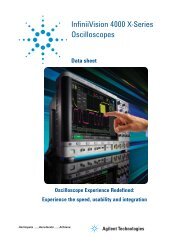
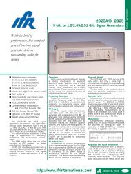
6 GHz Measurements<br />
The FCN4760 is a block down converter for the 4.7 to 6.0 GHz frequency range.<br />
It is designed to work with an Anritsu <strong>Site</strong> <strong>Master</strong> <strong>S332D</strong> equipped with Option 6.<br />
This converter is primarily intended for field use by fixed wireless engineers<br />
who are responsible for the design, deployment and optimization of 802.11a<br />
networks. It is also used to conduct interference analysis measurements to<br />
determine the level of interference and locate the sources of interference.<br />
Frequency Converter<br />
Control Module<br />
6
<strong>Site</strong> <strong>Master</strong> Options<br />
Power Monitor (Option 5, <strong>S331D</strong> and<br />
<strong>S332D</strong>)<br />
Use Anritsu’s 560 and 5400 series detector to measure<br />
broadband power. They are an excellent solution to measure an<br />
18 GHz microwave link carrying the Base Station T1/E1 link.<br />
The detectors use precision high return loss detectors with<br />
excellent impedance match designed to minimize mismatch<br />
uncertainty (See uncertainty curves on page 11). Measurement<br />
range is from –50 to +16 dBm and the display range is from<br />
–80 to +80 dBm. There are several detectors available designed<br />
for different frequency ranges.<br />
Frequency Converter Control Module Interface<br />
(Option 6, <strong>S332D</strong>)<br />
Connector providing internal control signals to work with the FCN4760, a block down converter designed for<br />
the 4.7 to 6 GHz frequency ranges (see page 6).<br />
Built-in Bias Tee (Option 10A, <strong>S332D</strong>)<br />
Built-in power supply can be turned on as needed to place +12 to +24V (variable in 1V steps) on the center conductor<br />
of the RF In port. It is designed to deliver 6W steady state.<br />
Transmission Measurement (Option 21, <strong>S332D</strong>)<br />
Built-in signal source from 25 MHz to 3 GHz provides the capability to make<br />
2-port measurements and measure gain, loss, or isolation of devices such as<br />
filters, cables, attenuators, amplifiers, and antennas.<br />
Calibration is a normal thru calibration. Padding the output with 20 dB will<br />
ensure linearity for active measurements and minimize source match errors<br />
resulting in very accurate measurements.<br />
Interference Analyzer (Option 25, <strong>S332D</strong>)<br />
The interference analyzer option displays interference in four different ways:<br />
Spectrogram, RSSI, Signal Strength, Signal ID.<br />
The spectrogram is a three dimensional display of frequency power and time<br />
of the spectrum activity to identify intermittent interference and track signal<br />
levels over time (three days). RSSI is useful to observe the signal strength<br />
at a single frequency over time (seven days).<br />
Signal Strength measurements can be made with a directional antenna to<br />
locate the interferer by measuring the strength of the interfering signal,<br />
which will be indicated by an audible beep.<br />
Signal ID can provide assistance in identifying signal types from<br />
cellular/PCS sites.<br />
7
<strong>Site</strong> <strong>Master</strong> Options<br />
Channel Scanner (Option 27, <strong>S332D</strong>)<br />
The Channel Scanner option measures the power of multiple transmitted signals,<br />
and is very useful for measuring the channel power of AMPS, iDEN, GSM, and<br />
TDMA networks.<br />
CW Signal (Option 28, <strong>S332D</strong>)<br />
Provides a CW signal from –6 dBm to –80 dBm in 1 dB step from 25 MHz to 2 GHz.<br />
The attenuator connected to the RF port can be varied from 0 to 90 dB in 1 dB steps<br />
and the splitter divides the signal into two signals: One is fed into the device under test<br />
and one is fed into the Spectrum Analyzer Receiver port. The display shows the output<br />
power and the frequency.<br />
Power Meter (Option 29, <strong>S331D</strong> and <strong>S332D</strong>)<br />
The power meter tool performs accurate transmitter power meter measurements<br />
from 4.5 MHz to 3 GHz reducing coverage holes and interference. The Spectrum<br />
Analyzer is used to measure the channel power and results can be displayed in<br />
dBm or Watts. No external detector is required.<br />
GPS Receiver (Option 31, <strong>S331D</strong> and <strong>S332D</strong>)<br />
Built-in GPS provides location information (latitude, longitude, and altitude) and Universal<br />
Time (UT) information. <strong>Site</strong> <strong>Master</strong> can stamp each trace with location information to check<br />
if the measurements are taken at the right location. <strong>Site</strong> <strong>Master</strong> stores the GPS location<br />
information until the unit is turned off. This stored location information can be used<br />
to stamp traces taken indoors at the same cell site location. The GPS option is<br />
offered with a magnet mount antenna with a 15-foot (~ 5m) cable to mount on<br />
the car or other useful surface.<br />
T1/E1 Analyzer (Option 50, <strong>S331D</strong>)<br />
<strong>Site</strong> <strong>Master</strong> built-in T1/E1 Analyzer performs T1/E1 functional tests, simplifying<br />
the task of determining if the source of the problem is on the wireline or the<br />
wireless side. <strong>Site</strong> <strong>Master</strong> can display the T1/E1 data in histogram form and collect<br />
the data for up to two days. <strong>Site</strong> <strong>Master</strong> can also measure the voltage (Vpp) of the<br />
signal and it can also be displayed as dBdsx.<br />
8
Handheld Software Tools <br />
Although <strong>Site</strong> <strong>Master</strong> features built-in analytical<br />
and reporting functions, users can also download<br />
measurement data to a PC for additional analysis or<br />
report generation. <strong>Site</strong> <strong>Master</strong>’s user friendly Software<br />
Tools is a Windows ® program designed specifically for<br />
cable and antenna analysis and will run on any<br />
computer with Windows 95/98/NT4/2000/ME/XP<br />
Test data can be analyzed and compared to historical<br />
performance.<br />
• Up to 200 <strong>Site</strong> <strong>Master</strong> trace memory locations can be downloaded with<br />
a single menu selection.<br />
• Build historical records with an unlimited number of traces in one document.<br />
• Familiar Windows 95/98/NT4/2000/ME/XP interface simplifies data analysis<br />
and report generation.<br />
• Intelligent drag and drop automatically converts traces to a common scale<br />
and speeds fault identification.<br />
• Supports long file names for easy measurement data identification.<br />
9
Specifications<br />
Cable and Antenna Analyzer<br />
Frequency Range: 25 MHz to 4.0 GHz<br />
Frequency Accuracy: ≤±75 ppm @ +25°C<br />
Frequency Resolution: 100 kHz<br />
Output Power: 42 dB corrected directivity after calibration<br />
Distance-to-Fault:<br />
Vertical Range: Return Loss: 0.00 to 60.00 dB<br />
VSWR 1.00 to 65.00<br />
Horizontal Range: 0 to (# of data pts –1) x<br />
Resolution to a maximum of 1197m (3929 ft),<br />
# of data pts = 130, 259 or 517<br />
Horizontal Resolution (Rectangular Windowing):<br />
Resolution (meter) = (1.5 x 10⁸) x (Vp)/DF<br />
Where Vp is the cable's relative propagation velocity<br />
and where DF is the stop frequency minus the start<br />
frequency (in Hz).<br />
Spectrum Analyzer (<strong>S332D</strong>)<br />
Frequency:<br />
Frequency Range: 100 kHz to 3.0 GHz (tunable to 9 kHz)<br />
Frequency Reference<br />
(Internal Timebase) Aging: ±1 ppm/yr<br />
Accuracy: ±2 ppm<br />
Frequency Span: 10 Hz to 2.99 GHz in 1, 2, and 5 step selections<br />
in auto mode, plus zero span<br />
Sweep Time: ≤1.1 sec full span<br />
≤50 µsec to 20 sec selectable in zero span<br />
Resolution Bandwidth (–3 dB): 100 Hz to 1 MHz in 1-3 sequence ±5%<br />
Accuracy<br />
Video Bandwidth (–3 dB): 3 Hz to 1 MHz in 1-3 sequence ±5%<br />
Accuracy typical<br />
SSB Phase Noise (1 GHz) @ 30 kHz Offset: ≤–75 dBc/Hz<br />
Spurious Responses Input Related: ≤–45 dBc<br />
Spurious Residual Responses: –90 dBm, ≤10 MHz<br />
≤–80 dBm, 2 GHz to 3 GHz<br />
±2 dB typical, 3 MHz to –30 dBm, 10 MHz to 2.4 GHz)<br />
Maximum Power: +20 dBm (0.1W) without external attenuator<br />
**(Excludes Input VSWR)<br />
GPS (Option 31)<br />
GPS Location Indicator<br />
Latitude, Longitude, and Altitude on Display<br />
Latitude, Longitude, and Altitude with trace storage<br />
T1 Analyzer (Option 50 <strong>S331D</strong> Only)<br />
Line Coding: AMI, B8ZS<br />
Framing Modes: D4 (Superframe)<br />
ESF (Extended Superframe)<br />
Connection Configurations: Terminate (100Ω)<br />
Bridge (≥1000Ω)<br />
Monitor (Connect via 20 dB pad in DSX)<br />
Receiver Sensitivity: 0 to –36 dBdsx<br />
Transmit Level: 0 dB, –7.5 dB, and –15 dB<br />
Clock Sources: External<br />
Internal 1.544 MHz ±30 ppm<br />
Pulse Shapes: Conform to ANSI T1.403<br />
Pattern Generation and Detection: PRBS: 2-9, 2-11, 2-15, 2-20, 2-23<br />
Inverted and non-inverted, QRSS,<br />
1-in-8 (1-in-7), 2-in-8, 3-in-24,<br />
All ones, All zeros, T1-Daly,<br />
User defined (≤32 bits)<br />
Circuit Status Reports: Carrier present, Frame ID and Sync,<br />
Pattern ID and Sync<br />
Alarm Detection: AIS (Blue Alarm), RAI (Yellow Alarm)<br />
Error Detection: Frame Bits, Bit, BER, BPV, CRC, Error Sec<br />
Error Insertion: Bit, BPV, Framing Bits, RAI, AIS<br />
Loopback Modes: Self loop, CSU, NIU, User defined, In-band or Data Link<br />
Level Measurements: Vp-p (± 5%)<br />
Data Log: Continuous, up to 48 hrs.<br />
E1 Analyzer (Option 50 <strong>S331D</strong> only)<br />
Line Coding: AMI, HDB3<br />
Framing Modes: PCM30, PCM30CRC, PCM31, PCM31CRC<br />
Connection Configurations: Terminate (75Ω, 120Ω)<br />
Bridge (≥1000Ω)<br />
Monitor (Connect via 20 dB pad in DSX)<br />
Receiver Sensitivity: 0 to –43 dB<br />
Transmit Level: 0 dB, –7.5 dB, and –15 dB<br />
Clock Sources: External<br />
Internal 2.048 MHz ±30 ppm<br />
Pulse Shapes: Conform to ITU G.703<br />
Pattern Generation and Detection: PRBS: 2-9, 2-11, 2-15, 2-20, 2-23<br />
Inverted and non-inverted, QRSS,<br />
1-in-8 (1-in-7), 2-in-8, 3-in-24, All<br />
ones, All zeros, T1-Daly, User defined<br />
(≤32 bits)<br />
Circuit Status Reports: Carrier present, Frame ID and Sync, Pattern ID<br />
and Sync<br />
Alarm Detection: AIS, RAI, MMF<br />
Error Detection: Frame Bits, Bit, BER, BPV, CRC, E-Bits, Error Sec<br />
Error Insertion: Bit, BPV, Framing Bits, RAI, AIS<br />
Loopback Modes: Self loopback<br />
Level Measurements: Vp-p (±5%)<br />
Data Log: Continuous, up to 48 hrs.<br />
General<br />
Language Support: Chinese, English, French, German, Japanese, Spanish<br />
Internal Trace Memory: 300 traces<br />
Setup Configuration: <strong>S332D</strong> - 20, <strong>S331D</strong> - 25<br />
Display: TFT color LCD with adjustable backlight<br />
Inputs and Outputs Ports:<br />
RF Out: Type N, female, 50Ω<br />
Maximum Input without Damage: +23 dBm, ±50 VDC<br />
RF In: Type N, female, 50Ω<br />
Maximum Input without Damage: +43 dBm (peak), ±50 VDC<br />
Ext. Trig In: BNC, female (5V TTL) (<strong>S332D</strong> Models only)<br />
Ext. Freq Ref In (2 to 20 MHz): Shared BNC, female, 50Ω,<br />
(–15 dBm to +10 dBm) (<strong>S332D</strong> Models only)<br />
T1/E1 (Receive and Transmit): Bantam Jack<br />
(<strong>S331D</strong> Models with Option 50 only)<br />
Serial Interface: RS-232 9 pin D-sub, three wire serial<br />
Electromagnetic Compatibility:<br />
Meets European Community requirements for CE marking<br />
Safety: Conforms to EN 61010-1 for Class 1 portable equipment<br />
Temperature:<br />
Operating: –10°C to 55°C, humidity 85% or less<br />
Non-operating: –51°C to +71°C (Recommend the battery be stored<br />
separately between 0°C and +40°C for any prolonged<br />
non-operating storage period.)<br />
Environmental: MIL-PRF-28800F Class 2<br />
Power Supply:<br />
External DC Input: +12.5 to +15 volt dc, 3A max<br />
Internal NiMH battery: 10.8 volts, 1800 mAH<br />
Dimensions:<br />
Size (w x h x d): 25.4 cm x 17.8 cm x 6.1 cm (10.0 in x 7.0 in x 2.4 in)<br />
Weight:
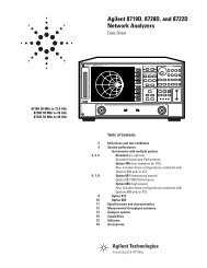
Specifications (Continued)<br />
The following graphs provide measurement uncertainty accuracy at 23°±C after vector error correction for the standard<br />
N connector types. The errors are worst-case contributions of residual directivity, source match, frequency response,<br />
network analyzer dynamic range, and connector repeatability. In preparing these graphs, Fixed CW is ON. Calibration<br />
components 22N50 and 28N50-2 are used.<br />
10<br />
Reflection Magnitude Uncertainty (<strong>S331D</strong>)<br />
100<br />
Reflection Phase Uncertainty (<strong>S331D</strong>)<br />
Uncertainty (dB)<br />
1<br />
0.025 GHz<br />
1 GHz<br />
4 GHz<br />
Uncertainty (Degrees)<br />
10<br />
0.025 GHz<br />
1 GHz<br />
4 GHz<br />
0.1<br />
0 10 20 30 40<br />
Return Loss (dB)<br />
Reflection Magnitude Uncertainty<br />
1<br />
0 10 20 40<br />
Return Loss (dB)<br />
Reflection Phase Uncertainty<br />
Using the 560-7N50B detector, the following curves show estimated power monitor uncertainties for various DUT match.<br />
1.6<br />
Estimated Power Monitor Uncertainty for Three DUT Match Levels at 18 GHz<br />
3<br />
Estimated Power Monitor Uncertainty for Three Frequencies at –30 dB Match<br />
Uncertainty (dB)<br />
1.4<br />
1.2<br />
1<br />
0.8<br />
Match= 30 dB<br />
Match= 20 dB<br />
Match= 10 dB<br />
Uncertainty (dB)<br />
2<br />
1<br />
3.3 GHz<br />
18 GHz<br />
20 GHz<br />
0.6<br />
0.4<br />
–50 –40 –30 –20 –10 0 10 20<br />
Power in (dBm)<br />
Estimated Power Monitor Uncertainty for<br />
Three DUT Match Levels at 18 GHz<br />
Power Monitor - Detectors<br />
0<br />
–50 –40 –30 –20 –10 0 10 20<br />
Power in (dBm)<br />
Estimated Power Monitor Uncertainty for<br />
Three Frequencies at –30 dB Match<br />
Model Frequency Range Impedance Return Loss Input Connector Frequency Response<br />
5400-71N50 0.001 to 3 GHz 50Ω 26 dB N(m)<br />
±0.2 dB,
<strong>Site</strong> <strong>Master</strong> Cell <strong>Master</strong><br />
S331C MS2712 <strong>Site</strong><strong>Master</strong> MT8212A Cell<strong>Master</strong> MS2712<br />
Ordering Information<br />
Base Model<br />
<strong>S331D</strong><br />
<strong>S332D</strong><br />
Options<br />
Option 5<br />
Option 6<br />
Option 10A<br />
Option 21<br />
Option 25<br />
Option 27<br />
Option 28<br />
Option 29<br />
Option 31<br />
Option 50<br />
Description<br />
Cable and Antenna Analyzer (25 MHz to 4.0 GHz),<br />
Cable and Antenna Analyzer (25 MHz to 4.0 GHz),<br />
Spectrum Analyzer (100 kHz to 3.0 GHz)<br />
Description<br />
Power Monitor - requires external detector (<strong>S331D</strong>/<strong>S332D</strong>)<br />
Frequency Converter Control Module Interface - can not be<br />
ordered with Option 5 (<strong>S332D</strong>)<br />
Bias Tee (<strong>S332D</strong>)<br />
Transmission Measurement (<strong>S332D</strong>)<br />
Interference Analyzer - requires color display and requires<br />
directional antenna (<strong>S332D</strong>)<br />
Channel Scanner (<strong>S332D</strong>)<br />
CW Signal Generator - requires CW Signal Generator Kit (S332)<br />
Power Meter - does not require external detector (<strong>S331D</strong>/<strong>S332D</strong>)<br />
GPS Receiver for location information. Includes GPS antenna<br />
(<strong>S331D</strong>/<strong>S332D</strong>)<br />
T1/E1 Analyzer - can not be ordered with Option 5 (<strong>S331D</strong>)<br />
Standard Accessories Include:<br />
10580-00079 <strong>S331D</strong>/<strong>S332D</strong> <strong>Site</strong> <strong>Master</strong> User's Guide<br />
2300-347 Anritsu Handheld Software Tools CDROM<br />
48258 Soft Carrying Case<br />
633-27 Rechargeable Battery, NiMH<br />
40-168 AC-DC Adapter with Power Cord<br />
806-141 Automotive Cigarette Lighter/12 Volt DC Adapter<br />
806-441 Serial Interface Cable<br />
One Year Warranty<br />
Optional Accessories<br />
FCN4760 Frequency Converter, 4.7 to 6.0 GHz<br />
1N50C Limiter, N(m) to N(f), 50Ω, 10 MHz to 18 GHz<br />
42N50-20 Attenuator, 20 dB, 5 watt, DC to 18 GHz, N(m)-N(f)<br />
42N50A-30 Attenuator, 30 dB, 50 watt, DC to 18 GHz, N(m)-N(f)<br />
ICN50 InstaCal Calibration Module, 2 MHz to 4.0 GHz, N(m), 50Ω<br />
22N50 Open/Short, DC to 18 GHz, N(m), 50Ω<br />
22NF50 Open/Short, DC to 18 GHz, N(f), 50Ω<br />
SM/PL Precision Load, DC to 4 GHz, 42 dB, N(m), 50Ω<br />
SM/PLNF Precision Load, DC to 4 GHz, 42 dB, N(f), 50Ω<br />
OSLN50LF Precision Open/Short/Load, DC to 4 GHz, 42 dB, 50Ω, N(m)<br />
OSLNF50LF Precision Open/Short/Load, DC to 4 GHz, 42 dB, 50Ω, N(f)<br />
2000-767 Precision Open/Short/Load, DC to 4 GHz, 7/16 DIN(m), 50Ω<br />
2000-768 Precision Open/Short/Load, DC to 4 GHz, 7/16 DIN(f), 50Ω<br />
15NN50-1.5C<br />
15NN50-3.0C<br />
15NN50-5.0C<br />
15NNF50-1.5C<br />
15NNF50-3.0C<br />
15NNF50-5.0C<br />
15ND50-1.5C<br />
15NDF50-1.5C<br />
34NN50A<br />
34NFNF50<br />
Test Port Cable Armored, 1.5 meters, N(m)-N(m), 6 GHz, 50Ω<br />
Test Port Cable Armored, 3.0 meters, N(m)-N(m), 6 GHz, 50Ω<br />
Test Port Cable Armored, 5.0 meters, N(m)-N(m), 6 GHz, 50Ω<br />
Test Port Cable Armored, 1.5 meters, N(m)-N(f), 6 GHz, 50Ω<br />
Test Port Cable Armored, 3.0 meters, N(m)-N(f), 6 GHz, 50Ω<br />
Test Port Cable Armored, 5.0 meters, N(m)-N(f), 6 GHz, 50Ω<br />
Test Port Cable Armored, 1.5 meters, N(m)-7/16 DIN(m), 6 GHz, 50Ω<br />
Test Port Cable Armored, 1.5 meters, N(m)-7/16 DIN(f),6 GHz, 50Ω<br />
Precision Adapter, N(m)-N(m), DC to 18 GHz, 50Ω<br />
Precision Adapter, N(f)-N(f), DC to 18 GHz, 50Ω<br />
1091-26 Adapter, N(m)-SMA(m), DC to 18 GHz, 50Ω<br />
1091-27 Adapter, N(m)-SMA(f), DC to 18 GHz, 50Ω<br />
1091-80 Adapter, N(f)-SMA(m), DC to 18 GHz, 50Ω<br />
1091-81 Adapter, N(f)-SMA(f), DC to 18 GHz, 50Ω<br />
1091-172 Adapter, N(m)-BNC(f), DC to 1.3 GHz, 50Ω<br />
510-90 Adapter, 7/16 DIN(f)-N(m), DC to 7.5 GHz, 50Ω<br />
510-91 Adapter, 7/16 DIN(f)-N(f), DC to 7.5 GHz, 50Ω<br />
510-92 Adapter, 7/16 DIN(m)-N(m), DC to 7.5 GHz, 50Ω<br />
510-93 Adapter, 7/16 DIN(m)-N(f), DC to 7.5 GHz, 50Ω<br />
510-96 Adapter, 7/16 DIN(m)-7/16 DIN(m), DC to 7.5 GHz, 50Ω<br />
510-97 Adapter, 7/16 DIN(f)-7/16 DIN(f), DC to 7.5 GHz, 50Ω<br />
61532 Antenna Kit:<br />
2000-1030 Portable Antenna, SMA(m), 1.71 to 1.88 GHz, 50Ω<br />
2000-1031 Portable Antenna, SMA(m), 1.85 to 1.99 GHz, 50Ω<br />
2000-1032 Portable Antenna, SMA(m), 2.4 to 2.5 GHz, 50Ω<br />
2000-1200 Portable Antenna, SMA(m), 806-869 MHz, 50Ω<br />
2000-1035 Portable Antenna, SMA(m), 896-941 MHz, 50Ω<br />
2000-1361 Portable Antenna, SMA(m), 5.725-5.825 MHz, 50Ω<br />
2000-1411 Portable YAGI Antenna, N(f), 822-900 MHz, 10 dBd<br />
2000-1412 Portable YAGI Antenna, N(f), 885-975 MHz, 10 dBd<br />
2000-1413 Portable YAGI Antenna, N(f), 1.71-1.88 GHz, 10 dBd<br />
2000-1414 Portable YAGI Antenna, N(f), 1.85-1.99 GHz, 9.3 dBd<br />
2000-1415 Portable YAGI Antenna, N(f), 2.4-2.5 GHz, 12 dBd<br />
2000-1416 Portable YAGI Antenna, N(f), 1.92-2.23 GHz, 12 dBd<br />
1030-109 Filter, Bandpass, 836.5 MHz Ctr Freq, 25.8 MHz BW,<br />
N(m) to SMA(f), 50Ω<br />
1030-110 Filter, Bandpass, 897.5 MHz Ctr Freq, 35 MHz BW,<br />
N(m) to SMA(f), 50Ω<br />
1030-111 Filter, Bandpass, 1.88 GHz Ctr Freq, 63.1 MHz BW,<br />
N(m) to SMA(f), 50Ω<br />
1030-112 Band Pass Filter, 2.442 GHz Ctr Freq, 85.1 MHz BW,<br />
N(m) to SMA(f), 50Ω<br />
2000-1410 Magnet Mount GPS Antenna with 15 ft. cable<br />
61534 CW Signal Generator Kit with variable step attenuator<br />
806-16 Bantam Plug to Bantam Plug<br />
806-116 Bantam Plug to BNC<br />
806-117 Bantam "Y" Plug to RJ48<br />
551-1691 USB to RS-232 adapter cable<br />
48258 Soft Carrying Case<br />
760-235 Transit Case<br />
633-27 Rechargeable Battery, NiMH<br />
2000-1029 Battery Charger, NiMH, w/ Universal Power Supply<br />
40-168 AC/DC Adapter<br />
806-141 Automotive Cigarette Lighter/12 Volts DC Adapter<br />
800-441 Serial Interface Cable<br />
2300-347 Software Tools<br />
Printers<br />
2000-1214 HP DeskJet Printer, Model 450: Includes printer cable, 2000-<br />
1216 black print cartridge and U.S. power cord. Also includes<br />
2000-753 serial-to-parallel Centronics converter cable and<br />
1091-310 Centronics-to DB25 adapter. Rechargeable battery<br />
is optional and is not included.<br />
2000-753 Null Modem Serial-to-Parallel Centronics Converter Cable<br />
1091-310 Adapter 36-pin Centronics female-to-DB25 female<br />
2000-1216 Black Print Cartridge<br />
2000-663 Power Cable (Europe) for DeskJet Printer<br />
2000-664 Power Cable (Australia) for DeskJet Printer<br />
2000-667 Power Cable (S. Africa) for DeskJet Printer<br />
2000-1217 Rechargeable Battery for DeskJet Printer, Model 450<br />
2000-1218 Power Cable (U.K.) for DeskJet Printer<br />
SALES CENTERS:<br />
United States (800) ANRITSU Europe 44 (0) 1582-433433 Microwave Measurement Division<br />
Canada (800) ANRITSU Japan 81 (46) 223-1111 490 Jarvis Drive, Morgan Hill, CA 95037-2809<br />
South America 55 (21) 2527-6922 Asia-Pacific (852) 2301-4980 http://www.us.anritsu.com<br />
PN: 11410-00366, Rev. C<br />
©Anritsu November 2005. All trademarks are registered<br />
trademarks of their respective companies. Data subject to<br />
change without notice. For most recent specifications visit<br />
www.us.anritsu.com.<br />
Discover What’s Possible ®