ERD â ElEctRic RoD-StylE ActuAtoR - Electromate Industrial Sales ...
ERD â ElEctRic RoD-StylE ActuAtoR - Electromate Industrial Sales ...
ERD â ElEctRic RoD-StylE ActuAtoR - Electromate Industrial Sales ...

Create successful ePaper yourself
Turn your PDF publications into a flip-book with our unique Google optimized e-Paper software.
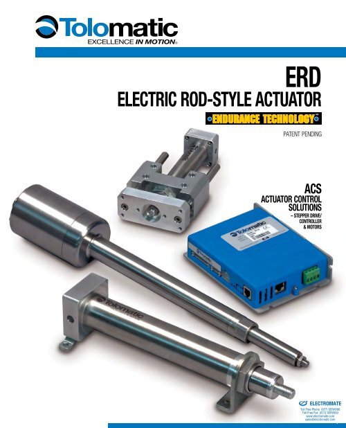
<strong>ERD</strong><br />
Electric Rod-Style Actuator<br />
PATENT PENDING<br />
ACS<br />
Actuator Control<br />
Solutions<br />
– Stepper Drive/<br />
controller<br />
& motors<br />
Sold & Serviced By:<br />
ELECTROMATE<br />
Toll Free Phone (877) SERVO98<br />
Toll Free Fax (877) SERV099<br />
www.electromate.com<br />
sales@electromate.com
<strong>ERD</strong> – Electric Rod-Style Actuator<br />
What is the <strong>ERD</strong>?<br />
The <strong>ERD</strong> is an economical rod-style electric actuator designed as an alternate to pneumatic cylinders and an option for<br />
automating manual processes. Combined with Tolomatic’s ACS stepper drive/controller, an extremely easy-to-use and cost<br />
effective actuator control solution is created. The <strong>ERD</strong>, with two different stainless steel options, is the industry’s first ever<br />
cataloged all stainless-steel electric actuator family intended for washdown environments.<br />
4 sizes, GD2 Guide Option<br />
Actuator Control Solutions,<br />
Drive & Motor Options<br />
First Ever Catalog All Stainless-<br />
Steel Electric Actuators<br />
Tolomatic’s ELECTRIC Rod-Style actuators<br />
<strong>ERD</strong> ICR SmartActuator ® RSA GSA IMA<br />
Thrust up to:<br />
Speed up to:<br />
Stroke Length<br />
up to:<br />
Rod-Style Actuator<br />
500 lbf<br />
[2224 N]<br />
40 in/sec<br />
[1016 mm/sec]<br />
24 in<br />
[609 mm]<br />
Integrated Control<br />
Rod-Style Actuator<br />
720 lbf<br />
[3202.7 N]<br />
25 in/sec<br />
[635 mm/sec]<br />
24 in<br />
[609 mm]<br />
Rod-Style Actuator<br />
7,000 lbf<br />
[31,138 N]<br />
123 in/sec<br />
[3,124 mm/sec]<br />
60 in<br />
[1,524 mm]<br />
Guided Rod-Style<br />
Actuator<br />
2,700 lbf<br />
[12,010 N]<br />
123 in/sec<br />
[3,124 mm/sec]<br />
36 in<br />
[914 mm]<br />
Integrated Motor<br />
Rod-Style Actuator<br />
3,300 lbf<br />
[14,679 N]<br />
23 in/sec<br />
[584 mm/sec]<br />
18 in<br />
[457 mm]<br />
Screw/Nut Type Solid & Ball Ball Solid, Ball & Roller Solid & Ball Ball & Roller<br />
For complete information see www.tolomatic.com or literature number:<br />
Sold & Serviced By:<br />
Literature Number: 2190-4000 2100-4000 3600-4609 3600-4609 2700-4000<br />
(Not all models deliver maximum values listed, i.e.: Maximum thrust may not be available with maximum speed)<br />
ELECTROMATE<br />
Toll Free Phone (877) SERVO98<br />
Toll Free Fax (877) SERV099<br />
www.electromate.com<br />
sales@electromate.com
<strong>ERD</strong> – Applications<br />
Press Fit, Pick & Place, Assembly<br />
Gating, Sorting, Diverting<br />
Aligning<br />
Product Change Over<br />
Optional all stainlesssteel<br />
design for washdown<br />
environments<br />
Heat Staking, Sonic Welding<br />
CONTENTS<br />
What is the <strong>ERD</strong> . . . . . .erd_2<br />
Rod-Style Actuators . . .erd_2<br />
Applications . . . . . . . . .erd_3<br />
FEATURES<br />
<strong>ERD</strong> . . . . . . . . . . . . . . .erd_4<br />
<strong>ERD</strong> SS2 . . . . . . . . . . .erd_6<br />
ACS. . . . . . . . . . . . . . .erd_8<br />
SPECIFICATIONS<br />
<strong>ERD</strong> . . . . . . . . . . . . . .erd_10<br />
Motors . . . . . . . . . . . .erd_11<br />
ACS. . . . . . . . . . . . . .erd_11<br />
Performance<br />
<strong>ERD</strong> . . . . . . . . . . . . . .erd_12<br />
GD2. . . . . . . . . . . . . .erd_14<br />
ACS & <strong>ERD</strong> . . . . . . . .erd_15<br />
DIMENSIONS<br />
<strong>ERD</strong> . . . . . . . . . . . . . .erd_16<br />
IP67 Option . . . . . . . .erd_16<br />
FM2, TRR, FFG . . . . . .erd_17<br />
GD2, SS2. . . . . . . . . .erd_18<br />
Tolomatic Motors . . . .erd_19<br />
Alternative Motors . . .erd_20<br />
ACS Dimensions. . . . .erd_21<br />
Switches . . . . . . . . .erd_22<br />
Appl. Data Worksheet erd_24<br />
Selection Guidelines . .erd_25<br />
Service Parts . . . . . . .erd_26<br />
Ordering. . . . . . . . . . .erd_27<br />
Other Applications:<br />
• Aligning<br />
• Animation<br />
• Assembly<br />
• Automatic tool changers<br />
• Automotive<br />
• Converting<br />
• Conveyors<br />
• Diverting<br />
• Fillers<br />
• Formers<br />
• Gating<br />
• Heat staking<br />
• Laser positioning<br />
• Material handling systems<br />
• Medical equipment<br />
• Motion simulators<br />
• Open / close doors<br />
• Packaging equipment<br />
• Parts clamping<br />
• Patient lifts<br />
• Pick & place<br />
• Plate positioning change<br />
• Press fit<br />
• Product changeover<br />
• Product test simulations<br />
• Robot manipulator arms<br />
• Sonic welding<br />
• Sorting<br />
• Table positioning<br />
• Tension control<br />
• Test stands<br />
• Volumetric pumps<br />
• Web guidance<br />
• Wire winding<br />
Sold & Serviced By:<br />
ELECTROMATE<br />
Toll Free Phone (877) SERVO98<br />
Toll Free Fax (877) SERV099<br />
www.electromate.com<br />
sales@electromate.com
<strong>ERD</strong> – Electric Rod-Style Actuator<br />
Endurance Technology features are<br />
designed for maximum durability to<br />
provide extended service life.<br />
The <strong>ERD</strong> is an economical rod-style electric actuator designed as an alternate to pneumatic<br />
cylinders and an option for automating manual processes. The <strong>ERD</strong> is compatible with many<br />
NEMA & metric mount stepper and servo motors to create a flexible, powerful electric actuator<br />
solution. Built-to-order in stroke lengths up to 24 inches.<br />
PaTENT Pending<br />
MULTIPLE SCREW TECHNOLOGIES<br />
You can choose:<br />
• Solid nuts of engineered resins<br />
offer quiet performance at the<br />
lowest cost<br />
• Ball nuts offer positioning<br />
accuracy and repeatability with<br />
longer life<br />
300 SERIES STaINLESSsteel<br />
MaIN TUBE<br />
• 300 Series stainless-steel main<br />
tube provides high rigidity and<br />
corrosion resistance<br />
… MAXIMUM DURABILITY<br />
Nema Motor Mount<br />
• <strong>ERD</strong>06: NEMA11 • <strong>ERD</strong>10: NEMA17<br />
• <strong>ERD</strong>15: NEMA23<br />
YOUR MOTOR HERE<br />
• <strong>ERD</strong>15 & 20: Over 500 motor mounts available<br />
with 5 day delivery.<br />
• <strong>ERD</strong>15: NEMA23 or 60mm metric<br />
• <strong>ERD</strong>20: NEMA23 or 60mm metric<br />
& NEMA34 or 80mm metric<br />
METRIC MOTOR Mount (option)<br />
• <strong>ERD</strong>10: 40mm Frame<br />
• Made of aluminum<br />
Not available for 06,15 & 20 sizes<br />
Oversized Main Bearing<br />
•Oversized for long life<br />
• Accommodates high thrust load<br />
MaLE THREaded<br />
Rod End<br />
•Standard metric threads<br />
•Compatible with many<br />
commercially available<br />
metric rod end accessories<br />
threadeD NOSE MOUNT<br />
With JaM NUT<br />
•Metric threads<br />
•Convenient mounting<br />
for many applications<br />
StaINLESS-Steel<br />
thrust tube<br />
• 300 series stainless-steel<br />
thrust tube provides high<br />
rigidity and corrosion<br />
resistance<br />
Nose BEARING<br />
•Engineered resins for<br />
smooth operation<br />
• Provides critical support<br />
of thrust rod<br />
INTEGRal Guide Rods<br />
and BeaRINGS<br />
•Stainless-steel guide rods provide high<br />
rigidity and low deflection<br />
•Four composite bearings support the<br />
load for smooth consistent motion<br />
INTERNal Magnet<br />
•This standard feature<br />
accommodates reed<br />
and solid state switches<br />
anywhere on the main tube<br />
Guide (GD2 option)<br />
•Load guidance, tooling<br />
plate and anti-rotate<br />
Options<br />
• TRR – trunnion mount<br />
For applications that require pivoting, 300 series stainless<br />
steel construction<br />
• FM2 – Foot mount*<br />
For applications that require bottom mounting, 300 series<br />
stainless steel construction<br />
• FFG – front Flange mounT*<br />
For front mounting applications, 300 series stainless steel<br />
construction<br />
• Switches*<br />
Choose from: Reed, Solid State PNP or NPN, all available in<br />
normally open<br />
• IP67 – IP67<br />
An IP67 upgrade (static rating) for protection against water<br />
and dust ingress (see page erd_6)<br />
• SS1 – Stainless steel<br />
Same <strong>ERD</strong> actuator made of all 300 series stainless steel for<br />
corrosion resistance. Available on all sizes.<br />
• SS2 – Stainless steel<br />
Sold & Serviced By:<br />
SS1 option plus IP67 and protective motor enclosure<br />
(see page erd_6) Not available for <strong>ERD</strong>06 & <strong>ERD</strong>20<br />
• GD2 – Guide<br />
ELECTROMATE<br />
Toll Free Phone (877) SERVO98<br />
Toll Free Fax (877) SERV099<br />
www.electromate.com<br />
sales@electromate.com<br />
For applications that require anti-rotation, or guidance and<br />
load bearing. Made of lightweight aluminum<br />
*NOTE: Foot Mount, Front Flange Mount and Switches are shipped<br />
together with the actuator but are not installed by Tolomatic.
<strong>ERD</strong> – Electric Rod-Style Actuator<br />
SS2 All 300 Series STAINless Steel, IP67, Motor Protection<br />
… MAXIMUM DURABILITY<br />
Endurance Technology features are<br />
designed for maximum durability to<br />
provide extended service life.<br />
The all 300 series stainless-steel <strong>ERD</strong> has an IP67 rating (static) that includes a protective<br />
enclosure for the standard Tolomatic motor. Built-to-order in stroke lengths up to 24 inches.<br />
Motor PROTECTION<br />
•Motor enclosure made of 300 series<br />
stainless steel designed to protect<br />
motor with IP67 rating (static)<br />
*NOTE: Only Tolomatic motors are<br />
available with the SS2 option.<br />
PaTENT Pending<br />
Viton ® Seals<br />
•For ingress protection<br />
and resistance to<br />
chemicals, water<br />
and dust<br />
•Used throughout<br />
actuator<br />
MULTIPLE SCREW TECHNOLOGIES<br />
You can choose:<br />
• Solid nuts of engineered<br />
resins offer quiet performance<br />
at the lowest cost<br />
• Ball nuts offer positioning<br />
accuracy and repeatability<br />
with longer life<br />
All 300 SERIES STaINLESS<br />
STEEL CONSTRUCTION<br />
• Corrosion resistant 300 series stainless<br />
steel is ideal for washdown environments<br />
Oversized Main Bearing<br />
•Oversized for long life<br />
• Accommodates high thrust load<br />
FlexIBLE<br />
CONNECTION<br />
• Choice of cord grips<br />
or industry standard<br />
conduit threads<br />
SS23<br />
1 or 2 cord grips<br />
determined if<br />
encoder is<br />
selected (polymide<br />
plastic)<br />
SS21<br />
NPT 1/2"<br />
conduit thread<br />
&<br />
SS22<br />
M20x1.5<br />
conduit thread<br />
MaLE THREaded<br />
Rod End<br />
•Standard metric threads<br />
•Compatible with many<br />
commercially available<br />
metric rod end accessories<br />
IP67 (static rating)<br />
Solids, first digit:<br />
6 Dust tight No ingress of dust; complete protection against solid object intrusion<br />
Liquids, second digit<br />
7 Immersion<br />
up to 1 m<br />
Ingress of water in harmful quantity shall not be possible when the enclosure is immersed<br />
in water under defined conditions of pressure and time (up to 1 m of submersion).<br />
(See page erd_11 for a complete definition of these IP codes)<br />
Nose BEARING<br />
•Engineered resins for<br />
smooth operation<br />
• Provides critical support<br />
of thrust rod<br />
INTERNal Magnet<br />
•This standard feature<br />
accommodates reed<br />
and solid state switches<br />
anywhere on the main tube<br />
Options<br />
• FM2 – Foot mount*<br />
For applications that require bottom mounting, 300 series<br />
stainless steel construction<br />
• FFG – front Flange mounT*<br />
For front mounting applications, 300 series stainless steel<br />
construction Sold & Serviced By:<br />
• Switches*<br />
Choose from: Reed, Solid State PNP or NPN, all available<br />
in normally open. (not corrosion resistant)<br />
*NOTE: Foot Mount, Front Flange Mount and Switches are shipped<br />
together with the actuator but are not installed by Tolomatic.<br />
ELECTROMATE<br />
Toll Free Phone (877) SERVO98<br />
Toll Free Fax (877) SERV099<br />
www.electromate.com<br />
sales@electromate.com
ACS – Actuator Control Solutions<br />
What is the ACS?<br />
The ACS is an extremely easy-to-use stepper drive & controller developed specifically to be used with electric actuators.<br />
Simply select the configured Tolomatic actuator in the software to automatically set-up most of the necessary parameters to<br />
create motion in the desired linear units (mm or inch).<br />
ACS Drive/controller (3604-9651) Capabilities:<br />
• 4, 8, or 16 move command modes (absolute, incremental, jog or<br />
home with analog output echoing position of actuator from<br />
encoder) for infinite positioning capability<br />
• Analog position mode (0-10 Vdc or 4-20 mA)<br />
• Pneumatic mode replaces pneumatic valve logic for simple motion<br />
• ModBus RTU over RS485 provides infinite positioning<br />
• Adjustable motion profile parameters (velocity, accel/decel, force).<br />
Parameters are independently configurable for each move<br />
• Ability to reduce holding current for energy savings<br />
• End point correction<br />
• Zone output based on position<br />
• Force limiting capability<br />
• Configurable digital I/O<br />
(24 Vdc Opto-Isolated)(NPN or PNP)<br />
• Compatible with most<br />
24 Vdc stepper motors<br />
ACS Drive/controller (3604-9654, 3604-9655) Additional Capabilities:<br />
• Ethernet mode provides infinite positioning using EtherNet/IP<br />
and Modbus TCP protocols<br />
• Dual Ethernet ports with internal switch for daisy chaining<br />
• Analog output for Analog Position Mode<br />
Sold & Serviced By:<br />
ELECTROMATE<br />
Toll Free Phone (877) SERVO98<br />
Toll Free Fax (877) SERV099<br />
www.electromate.com<br />
sales@electromate.com
ACS – Actuator Control Solutions<br />
dUAL ETHERNET PORTS (option)<br />
• Internal switch for daisy chaining up to 255 ACS axes<br />
Protocols:<br />
• EtherNet/IP • Modbus TCP • Ethernet TCP/IP<br />
dUAL PURPOSE Heat Sink<br />
• Removes heat from drive<br />
for optimal performance<br />
• Panel mounting<br />
dIGITAL I/0<br />
• 8 Digital Inputs<br />
• 4 Digital Outputs<br />
•24 Vdc Opto-Isolated<br />
• NPN or PNP<br />
• Configurable<br />
ANALOG I/0<br />
• 0-10 Vdc or 4-20mA<br />
• 1 Analog Input<br />
• 1 Analog Output<br />
(Optional)<br />
Feedback<br />
•For Digital Encoder<br />
Motor Power<br />
•24Vdc Stepper Motors<br />
LED indICATORS<br />
•Power & Fault indicators<br />
rs232 COM PORT<br />
• Drive Configuration Port<br />
Power<br />
CONNECTION<br />
rs485 COM PORT<br />
• Modbus RTU<br />
• 24Vdc<br />
Easy to use configuration software<br />
• Windows ®<br />
compliant<br />
Sold & Serviced By:<br />
ELECTROMATE<br />
Toll Free Phone (877) SERVO98<br />
Toll Free Fax (877) SERV099<br />
www.electromate.com<br />
sales@electromate.com
<strong>ERD</strong> – Electric Rod-Style Actuator<br />
SIZE: ALL<br />
sizing software<br />
available at www.<br />
tolomatic.com<br />
SPECIFICATIONS (US standard measurement)<br />
<strong>ERD</strong> SIZE<br />
SCREW<br />
DIA.<br />
MAXIMUM<br />
STROKE*<br />
SCREW<br />
CODE<br />
LEAD<br />
LEAD<br />
Accu RACY<br />
BACKLASH<br />
MAXIMUM<br />
THRUST<br />
DYNAMIC<br />
LOAD<br />
RATING<br />
WEIGHT WEIGHT<br />
INERTIA WEIGHT (GD2 adder) (SS2 adder)<br />
Base Per Inch Base Per Inch Base Per Inch Base Per Inch<br />
in in in/rev in/ft in lbf lbf lb-in 2 lb-in 2 lb lb lb lb lb lb<br />
SN02 0.500<br />
06 0.250 8 SN04 0.250 0.005<br />
20 NA 0.0018 0.0001 0.263 0.035 0.579 0.027 – –<br />
SN16 0.063<br />
SN01 1.000<br />
0.007<br />
10<br />
0.375<br />
SN02 0.500 0.007 40 NA 0.0022 0.0006 0.411 0.069<br />
0.069<br />
10<br />
1.028 0.061 2.280<br />
SN05 0.200<br />
0.472 BNM05 0.197 0.004 0.005 100 240 0.0040 0.0014 0.607 0.087 0.087<br />
SN01 1.000 0.006<br />
0.500 12 SN02 0.500 0.005 0.007 75 NA 0.0104 0.0017 1.079 0.126<br />
0.126<br />
15<br />
SN05 0.200 0.006<br />
2.297 0.095 5.771<br />
0.630 24<br />
BNM05 0.197<br />
450<br />
0.004 0.005 200<br />
BNM10 0.394 400<br />
0.0178 0.0044 1.170 0.159 0.159<br />
20 0.984 24<br />
BNM05 0.197<br />
BNM10 0.394<br />
0.004 0.005 500 900 0.0628 0.0263 7.575 0.325 6.455 0.256 – –<br />
SPECIFICATIONS (metric measurement)<br />
<strong>ERD</strong> SIZE<br />
SCREW<br />
DIA.<br />
MAXIMUM<br />
STROKE*<br />
SCREW<br />
CODE<br />
LEAD<br />
LEAD<br />
Accu RACY<br />
BACKLASH<br />
MAXIMUM<br />
THRUST<br />
DYNAMIC<br />
LOAD<br />
RATING<br />
INERTIA<br />
WEIGHT<br />
WEIGHT<br />
(GD2 adder)<br />
WEIGHT<br />
(SS2 adder)<br />
Base Per 25mm Base Per 25mm Base Per 25mm Base Per 25mm<br />
mm mm mm/rev<br />
mm/<br />
300mm mm N N<br />
kg-m 2 x<br />
10 -6 kg-m 2 x<br />
10 -6 kg kg kg kg kg kg<br />
SN02 12.7<br />
06 6.35 203.2 SN04 6.35 0.13<br />
89 NA 0.53 0.03 0.119 0.016 0.263 0.012 – –<br />
SN16 1.60<br />
SN01 25.4<br />
0.18<br />
10<br />
9.53<br />
SN02 12.7 0.18 188 NA 0.64 0.18 0.186 0.031<br />
0.031<br />
254.0<br />
0.466 0.028 2.280<br />
SN05 5.08<br />
12.00 BNM05 5.00 0.87 0.13 445 1068 1.16 0.41 0.275 0.039 0.039<br />
SN01 25.4 0.15<br />
12.70 304.8 SN02 12.7 0.13 0.18 334 NA 3.04 0.50 0.489 0.057<br />
0.057<br />
15<br />
SN05 5.08 0.15<br />
1.042 0.043 5.771<br />
16.00 609.6<br />
BNM05 5.00<br />
2002<br />
0.87 0.13 890<br />
BNM10 10.00 1779<br />
5.18 1.28 0.531 0.072 0.072<br />
20 25.00 609.6<br />
BNM05 5.00<br />
BNM10 10.00<br />
0.87 0.13 2224 4003 18.38 7.7 3.436 0.147 2.928 0.116 – –<br />
Temperature range<br />
IP rating<br />
40° to 130° F<br />
(4.4° to 54.4° C)<br />
40 (static)<br />
*Longer stroke length modification<br />
available upon request.<br />
Side Load Considerations<br />
The standard <strong>ERD</strong> rod-style actuator is not meant to be used in<br />
applications where side loading occurs. If side loading exists in<br />
the application consider the GD2 guided option.<br />
Loads must be guided and supported. Loads should be aligned<br />
with the line of motion of the thrust rod.<br />
Side loading will affect the life of the actuator.<br />
Sold & Serviced By:<br />
ELECTROMATE<br />
Toll Free Phone (877) SERVO98<br />
Toll Free Fax (877) SERV099<br />
www.electromate.com<br />
sales@electromate.com
<strong>ERD</strong> – Electric Rod-Style Actuator<br />
SIZE: ALL<br />
MOTOR SPECIFICATIONS<br />
Specifications NEMA 11 NEMA 17 NEMA 23<br />
Motor Type<br />
Bipolar Stepper, 1.8° per Step<br />
Encoder<br />
Differential; 500 line (2000 count post quad)<br />
Resistance 3.5 Ω 2.4 Ω 1.5 Ω<br />
Inductance 2.3 mH 4.5 mH 3.7 mH<br />
Rated Current 1 Arms 1.5 Arms 2 Arms<br />
Maximum Torque 0.813 in-lbs 0.092 N-m 4.4 in-lbs 0.497 N-m 6.25 in-lbs 0.706 N-m<br />
Maximum RPM 1500 RPM 900 RPM 1050 RPM<br />
Degree per Step 1.8° 1.8° 1.8°<br />
Rotor Inertia 0.006 lb-in 2 17.588 g-cm 2 0.028 lb-in 2 81.939 g-cm 2 0.075 lb-in 2 219.481 g-cm 2<br />
ACS Drive/Controller SPECIFICATIONS<br />
Drive power<br />
Current - Max 4A<br />
Voltage Nominal 20 - 28V<br />
Over Voltage 30V<br />
Under Voltage 18V<br />
Absolute Maximum Voltage 35V<br />
Logic Current Draw (24V) 100 mA<br />
See ACS Hardware and Installation Guide #3604-4173 for more details.<br />
Operating conditions<br />
Ambient Temperature 77°F, 25°C Nominal<br />
Operating Temperature 32 - 104°F, 0 - 40°C<br />
Storage Temperature 32-158°F, 0-70°C<br />
Humidity 0 - 90% non-condensing<br />
What Does IP67 mean?<br />
The IP Code (or International Protection<br />
Rating) consists of the letters IP followed by<br />
two digits and an optional letter. As defined in<br />
international standard IEC 60529, it classifies<br />
the degrees of protection provided against<br />
the intrusion of solid objects (including body<br />
parts like hands and fingers), dust, accidental<br />
contact, and water in electrical enclosures.<br />
Solids, first digit:<br />
4 >1 mm Most wires, screws, etc.<br />
6 Dust tight No ingress of dust; complete protection against solid object<br />
intrusion<br />
Liquids, second digit (static rating)<br />
0 Not protected<br />
7 Immersion up<br />
to 1 m<br />
Ingress of water in harmful quantity shall not be possible when<br />
the enclosure is immersed in water under defined conditions of<br />
pressure and time (up to 1 m of submersion).<br />
The first digit indicates the level of<br />
protection that the enclosure provides<br />
against access to hazardous parts (e.g.,<br />
electrical conductors, moving parts) and the<br />
ingress of solid foreign objects.<br />
The second digit indicates the level of<br />
protection that the enclosure provides<br />
against harmful ingress of water.<br />
Sold & Serviced By:<br />
ELECTROMATE<br />
Toll Free Phone (877) SERVO98<br />
Toll Free Fax (877) SERV099<br />
www.electromate.com<br />
sales@electromate.com
0<br />
40<br />
<strong>ERD</strong> – Electric Rod-Style Actuator<br />
SIZE: ALL<br />
ACME & BALL SCREW/NUT CRITICAL SPEED CAPACITIES<br />
STROKE (mm)<br />
76<br />
152 229<br />
76<br />
40<br />
STROKE (mm)<br />
152 229<br />
305<br />
1,016<br />
PERFORMANCE<br />
10 10 SN01 SN01<br />
10 10 SN05 SN05<br />
10BNM05<br />
10 10 SN02 SN02<br />
SPEED (in/sec)<br />
30<br />
20<br />
10<br />
06 SN02<br />
06 SN04<br />
SPEED (in/sec)<br />
30<br />
20<br />
10<br />
762<br />
508<br />
254<br />
SPEED (mm/sec)<br />
0<br />
0<br />
76<br />
40<br />
<strong>ERD</strong>06<br />
06 SN16<br />
3 6<br />
9<br />
STROKE (in)<br />
STROKE (mm)<br />
<strong>ERD</strong>10<br />
0<br />
3 9<br />
6<br />
STROKE (in)<br />
152 229 305 381 457 533 610<br />
15 SN01<br />
0<br />
12<br />
STROKE (mm)<br />
381 457 533<br />
610<br />
40<br />
1,016<br />
SPEED (in/sec)<br />
30<br />
20<br />
10<br />
<strong>ERD</strong>15<br />
0<br />
3 9<br />
6<br />
STROKE (in)<br />
15 SN02<br />
15BNM10<br />
15BNM05<br />
15 SN05<br />
12 15 18 21<br />
24<br />
NOTE: Only ballscrew (BNMxx)<br />
units are available to 24" stroke<br />
SPEED (in/sec)<br />
30<br />
20<br />
10<br />
<strong>ERD</strong>20<br />
20BNM10<br />
20BNM05<br />
0<br />
0<br />
15 18 21<br />
24<br />
STROKE (in)<br />
762<br />
508<br />
254<br />
SPEED (mm/sec)<br />
MAXIMUM THRUST vs STROKE<br />
STROKE (mm)<br />
0 127 254 381 508 635<br />
500<br />
2224<br />
20 BN<br />
400<br />
1779<br />
THRUST (lbf)<br />
300<br />
200<br />
15 BN<br />
1334<br />
890<br />
THRUST (N)<br />
100<br />
10 BN<br />
15 SN<br />
445<br />
0<br />
0<br />
06 SN02<br />
10 SN<br />
06 SN04+16<br />
5 10 15 20<br />
STROKE (in)<br />
0<br />
25<br />
Sold & Serviced By:<br />
ELECTROMATE<br />
Toll Free Phone (877) SERVO98<br />
Toll Free Fax (877) SERV099<br />
www.electromate.com<br />
sales@electromate.com
<strong>ERD</strong> – Electric Rod-Style Actuator<br />
SIZE: ALL<br />
PERFORMANCE<br />
sizing software<br />
available at www.<br />
tolomatic.com<br />
PV LIMITS (Pressure Velocity of Acme Nut)<br />
SPEED (mm/sec)<br />
0 254 508 762<br />
80<br />
1,016<br />
356<br />
60<br />
15 SN05<br />
15 SN02<br />
15 SN01<br />
267<br />
THRUST (lbf)<br />
40<br />
10 10 SN05 SN05<br />
10 SN02<br />
10 SN01<br />
178<br />
THRUST (N)<br />
20<br />
06 SN04<br />
06 SN02<br />
89<br />
06 SN16<br />
0<br />
0<br />
10 20 30<br />
SPEED (in/sec)<br />
PV LIMITS: Any material which carries a sliding load is limited by heat buildup. The<br />
factors that affect heat generation rate in an application are the pressure on the<br />
nut in pounds per square inch and the surface velocity in feet per minute. The<br />
product of these factors provides a measure of the severity of an application.<br />
0<br />
40<br />
P x V ≤ 0.1<br />
( Thrust Speed<br />
((Max. Thrust Rating))<br />
x<br />
((Max. Speed Rating))<br />
≤ 0.1<br />
BALL SCREW LIFE<br />
0 222 445 667 890<br />
100,000<br />
THRUST (N)<br />
1112 1334 1557 1779<br />
2002 2224<br />
2,540,000<br />
10,000<br />
254,000<br />
LIFE (million in)<br />
1,000<br />
100<br />
10<br />
15BNM10<br />
15BNM05<br />
20BNM10<br />
20BNM05<br />
25,400<br />
2,540<br />
254<br />
LIFE (million mm)<br />
10BNM05<br />
1<br />
0<br />
15BNM10<br />
50 100 150<br />
NOTE: The L 10 expected life of a ball<br />
screw linear actuator is expressed as<br />
the linear travel distance that 90%<br />
of properly maintained ball screw<br />
manufactured are expected to meet<br />
or exceed. This is not a guarantee and<br />
this graph should be used for estimation<br />
purposes only.<br />
200<br />
250 300 350 400<br />
THRUST (lbf)<br />
The underlying formula<br />
that defines this value is:<br />
L 10 = (<br />
C<br />
) 3 • l ≡<br />
F<br />
Travel life in millions of inches, where:<br />
C = Dynamic load rating (lbf)<br />
F = Equivalent load (lbf)<br />
l = Screw lead (in/rev)<br />
25<br />
450 500<br />
Use the "Equivalent Load" calculation below, when the load<br />
is not constant throughout the entire stroke. In cases where<br />
there is only minor variation in loading, use greatest load for<br />
life calculations.<br />
P e =<br />
√ 3 %(P 1) 3 +%(P 2 ) 3 +%(P 3 ) 3 +%(P n ) 3<br />
Where:<br />
P e = Equivalent load (lbs)<br />
100<br />
P n = Each increment at different load (lbs)<br />
% n = Percentage of stroke at load increment<br />
Sold & Serviced By:<br />
ELECTROMATE<br />
Toll Free Phone (877) SERVO98<br />
Toll Free Fax (877) SERV099<br />
www.electromate.com<br />
sales@electromate.com
<strong>ERD</strong> – Electric Rod-Style Actuator<br />
OPTION: GD2 – GUIDED <strong>ERD</strong><br />
Load vs extended length<br />
PERFORMANCE<br />
sizing software<br />
available at www.<br />
tolomatic.com<br />
06, 10, 15 15, 20<br />
Xs – STROKE LENGTH (mm)<br />
Xs – STROKE LENGTH (mm)<br />
25<br />
25<br />
51<br />
76<br />
102<br />
127<br />
152<br />
178<br />
203<br />
229<br />
254<br />
279<br />
305<br />
11.3<br />
100<br />
51<br />
102<br />
152<br />
203<br />
254<br />
305<br />
356<br />
406<br />
457<br />
508<br />
559<br />
610<br />
45<br />
W — LOAD WEIGHT (lbs)<br />
20<br />
15<br />
10<br />
5<br />
0<br />
<strong>ERD</strong>06<br />
<strong>ERD</strong>10<br />
0<br />
1 2 3 4 5 6 7 8 9 10 11 12<br />
Xs – STROKE LENGTH (in)<br />
9.1<br />
6.8<br />
4.5<br />
<strong>ERD</strong>15<br />
2.3<br />
W — LOAD WEIGHT (kg)<br />
(12" to 24"<br />
at right)<br />
W — LOAD WEIGHT (lbs)<br />
80<br />
60<br />
40<br />
20<br />
0<br />
9<br />
<strong>ERD</strong>20<br />
<strong>ERD</strong>15<br />
2 4 6<br />
0<br />
8 10 12 14 16 18 20 22 24<br />
Xs – STROKE LENGTH (in)<br />
W<br />
36<br />
27<br />
18<br />
W — LOAD WEIGHT (kg)<br />
Bending Moments<br />
06, 10, 15 15, 20<br />
Xs – STROKE LENGTH (mm.)<br />
Xs – STROKE LENGTH (mm.)<br />
Mx<br />
Xs<br />
40<br />
25<br />
51<br />
76<br />
102<br />
127<br />
152<br />
178<br />
203<br />
229<br />
254<br />
279<br />
305<br />
4.5<br />
200<br />
51<br />
102<br />
152<br />
203<br />
254<br />
305<br />
356<br />
406<br />
457<br />
508<br />
559<br />
610<br />
22.6<br />
Mx — MOMENT (in-lbs)<br />
30<br />
20<br />
10<br />
0<br />
<strong>ERD</strong>10<br />
Xs – STROKE LENGTH (in.)<br />
3.4<br />
2.3<br />
<strong>ERD</strong>06<br />
0<br />
1 2 3 4 5 6 7 8 9 10 11 12<br />
Mx — MOMENT (N-m)<br />
Mx — MOMENT (in-lbs)<br />
150<br />
100<br />
1.1<br />
50<br />
<strong>ERD</strong>15 (12" to 24"<br />
at right)<br />
0<br />
2 4 6 8 10 12<br />
Xs – STROKE LENGTH (in.)<br />
<strong>ERD</strong>20<br />
<strong>ERD</strong>15<br />
14 16 18 20 22<br />
0<br />
24<br />
16.9<br />
11.3<br />
5.6<br />
Mx — MOMENT (N-m)<br />
Guide Rod Deflection<br />
NOTE: Deflection is measured at the tooling plate.<br />
Excessive deflection may impact actuator life.<br />
Contact Tolomatic for assistance<br />
06 10<br />
Xs – STROKE LENGTH (mm.)<br />
Xs – STROKE LENGTH (mm.)<br />
15<br />
Xs – STROKE LENGTH (mm.)<br />
20<br />
Xs – STROKE LENGTH (mm.)<br />
0.300<br />
25<br />
51<br />
76<br />
102<br />
127<br />
152<br />
178<br />
203<br />
229<br />
254<br />
279<br />
305<br />
7.62<br />
0.150<br />
25<br />
51<br />
76<br />
102<br />
127<br />
152<br />
178<br />
203<br />
229<br />
254<br />
279<br />
305<br />
16 lbs<br />
3.81<br />
0.700<br />
51<br />
102<br />
152<br />
203<br />
254<br />
305<br />
356<br />
406<br />
457<br />
508<br />
559<br />
610<br />
17.78<br />
0.600<br />
51<br />
102<br />
152<br />
203<br />
254<br />
305<br />
356<br />
406<br />
457<br />
508<br />
559<br />
610<br />
15.24<br />
0.250<br />
12 lbs (5.4 kg)<br />
9 lbs (4.1 kg)<br />
6 lbs (2.7 kg)<br />
3 lbs (1.4 kg)<br />
12 lbs<br />
6.35<br />
16 lbs (7.3 kg)<br />
12 lbs (5.4 kg)<br />
8 lbs (3.6 kg)<br />
4 lbs (1.8 kg)<br />
12 lbs<br />
0.600<br />
20 lbs (9.1 kg)<br />
15 lbs (6.8 kg)<br />
10 lbs (4.5 kg)<br />
5 lbs (2.3 kg)<br />
20 lbs<br />
15.24<br />
0.500<br />
80 lbs (36.3 kg)<br />
60 lbs (27.2 kg)<br />
40 lbs (18.1 kg)<br />
20 lbs (9.1 kg)<br />
80 lbs<br />
12.70<br />
0.200<br />
9 lbs<br />
5.08<br />
0.100<br />
2.54<br />
0.500<br />
15 lbs<br />
12.70<br />
0.400<br />
60 lbs<br />
10.16<br />
DEFLECTION (in)<br />
0.150<br />
6 lbs<br />
3.81<br />
DEFLECTION (mm)<br />
DEFLECTION (in)<br />
8 lbs<br />
4 lbs<br />
DEFLECTION (mm)<br />
DEFLECTION (in)<br />
0.400<br />
0.300<br />
10 lbs<br />
10.16<br />
7.62<br />
DEFLECTION (mm)<br />
DEFLECTION (in)<br />
0.300<br />
40 lbs<br />
7.62<br />
DEFLECTION (mm)<br />
0.100<br />
0.050<br />
0<br />
3 lbs<br />
0<br />
1 2 3 4 5 6 7 8 9 10 11 12<br />
Xs – STROKE LENGTH (in.)<br />
2.54<br />
1.27<br />
0.050<br />
0<br />
0<br />
1 2 3 4 5 6 7 8 9 10 11 12<br />
Xs – STROKE LENGTH (in.)<br />
1.27<br />
0.200<br />
0.100<br />
0 0<br />
2 4 6 8 10 12 14 16 18 20 22 24<br />
Xs – STROKE LENGTH (in.)<br />
5 lbs<br />
5.08<br />
2.54<br />
0.200<br />
0.100<br />
0<br />
20 lbs<br />
Sold & Serviced By:<br />
Toll Free 0 Phone (877) SERVO98<br />
22 24<br />
2 4 6 8 10 12 14 16 18 20<br />
Xs – STROKE LENGTH (in.)<br />
5.08<br />
2.54<br />
ELECTROMATE<br />
Toll Free Fax (877) SERV099<br />
www.electromate.com<br />
sales@electromate.com
<strong>ERD</strong> – Electric Rod-Style Actuator<br />
PERFORMANCE DATA WITH ACS Drive/Controller<br />
SPEED vs THRUST - <strong>ERD</strong>06 actuator with nema11 motor<br />
sizing software<br />
available at www.<br />
tolomatic.com<br />
THRUST (lbf)<br />
0 50<br />
20<br />
18<br />
16<br />
14<br />
12<br />
10<br />
8<br />
6<br />
4<br />
2<br />
SN16<br />
SPEED(mm/sec)<br />
100 150 200 250 300<br />
89<br />
SN04<br />
SN02<br />
0<br />
0<br />
0 1 2 3 4 5 6 7 8 9 10 11<br />
SPEED(in/sec)<br />
80<br />
SN02<br />
71<br />
SN04<br />
SN16<br />
62<br />
53<br />
44<br />
36<br />
27<br />
18<br />
8.9<br />
THRUST (N)<br />
SS2 Option is not available<br />
for the 06 size<br />
THRUST (lbf)<br />
0<br />
80<br />
70<br />
60<br />
50<br />
40<br />
30<br />
20<br />
10<br />
SPEED vs THRUST - <strong>ERD</strong>10 actuator with nema17 motor<br />
SN05 SN05<br />
50<br />
BNM05<br />
SPEED(mm/sec)<br />
100 150 200 250 300<br />
356<br />
SN02<br />
SN01<br />
SN02<br />
SN05<br />
BNM05<br />
SN01<br />
0<br />
0<br />
0 1 2 3 4 5 6 7 8 9 10 11<br />
SPEED(in/sec)<br />
311<br />
267<br />
222<br />
178<br />
133<br />
89<br />
45<br />
THRUST (N)<br />
THRUST (lbf)<br />
0<br />
80<br />
70<br />
60<br />
50<br />
40<br />
30<br />
20<br />
10<br />
SN05 SN05<br />
50<br />
BNM05<br />
SN02<br />
SPEED(mm/sec)<br />
100 150 200 250 300<br />
356<br />
SN01<br />
SN02<br />
SN05<br />
BNM05<br />
CONTINUOUS WITH SS2 OPTION<br />
(SEE GRAPH AT LEFT FOR PEAK)<br />
SN01<br />
0<br />
0<br />
0 1 2 3 4 5 6 7 8 9 10 11<br />
SPEED(in/sec)<br />
311<br />
267<br />
222<br />
178<br />
133<br />
89<br />
45<br />
THRUST (N)<br />
THRUST (lbf)<br />
0<br />
160<br />
140<br />
120<br />
100<br />
80<br />
60<br />
40<br />
20<br />
0<br />
SPEED vs THRUST - <strong>ERD</strong>15 actuator with nema23 motor<br />
50<br />
BNM05<br />
SN05<br />
100 150 200 250 300 350<br />
712<br />
BNM10<br />
SPEED(mm/sec)<br />
SN02<br />
SN01<br />
SN02<br />
SN05<br />
BNM05<br />
BNM10<br />
0 2 4 6 8 10 12<br />
SPEED(in/sec)<br />
SN01<br />
623<br />
534<br />
445<br />
356<br />
267<br />
178<br />
89<br />
0<br />
THRUST (N)<br />
THRUST (lbf)<br />
0<br />
160<br />
140<br />
120<br />
100<br />
80<br />
60<br />
40<br />
20<br />
50<br />
SN05 SN05<br />
BNM05 BNM05<br />
SPEED(mm/sec)<br />
100 150 200 250 300 350<br />
712<br />
SN02<br />
BNM10<br />
SN01<br />
SN02<br />
SN05<br />
BNM05<br />
BNM10<br />
CONTINUOUS WITH SS2 OPTION<br />
(SEE GRAPH AT LEFT FOR PEAK)<br />
0<br />
0 2 4 6 8 10 12<br />
SPEED(in/sec)<br />
SN01<br />
623<br />
534<br />
445<br />
356<br />
267<br />
178<br />
89<br />
0<br />
THRUST (N)<br />
Sold & Serviced By:<br />
ELECTROMATE<br />
Toll Free Phone (877) SERVO98<br />
Toll Free Fax (877) SERV099<br />
www.electromate.com<br />
sales@electromate.com
<strong>ERD</strong> – Electric Rod-Style Actuator<br />
ACTUATOR<br />
S MAX<br />
DIMENSIONS<br />
3D CAD available at www.tolomatic.com<br />
A<br />
<strong>ERD</strong>15<br />
A<br />
B<br />
(MOTOR SHAFT<br />
INTERFACE)<br />
C<br />
R<br />
T<br />
O<br />
P<br />
E<br />
Q<br />
N (SHCS) CPLR<br />
F + STROKE<br />
FOOT MOUNT IP67 OPTION Option DIMENSIONS<br />
A<br />
B<br />
C<br />
U<br />
D<br />
E<br />
F<br />
G<br />
H<br />
I<br />
M<br />
G<br />
II<br />
L<br />
H<br />
I<br />
K<br />
JAM NUT<br />
<strong>ERD</strong>06 <strong>ERD</strong>10 <strong>ERD</strong>15 <strong>ERD</strong>20<br />
in 1.125 1.580 2.220*<br />
P<br />
mm 28.58 V + STROKE 40.13 56.39*<br />
in Ø1.287 Ø1.725 Ø2.625*<br />
mm Ø32.69 Ø43.82 Ø66.68*<br />
in - - -<br />
mm - - M4 x 0.7*<br />
W<br />
in Ø.136 Ø.154 -<br />
mm Ø3.45 Ø3.91 -<br />
in 1.400 0.740 0.850*<br />
mm 35.56 18.80 21.59*<br />
in X3.88 4.20 5.40*<br />
mm 98.5 106.7 137.2*<br />
in 0.500 0.500 0.600 0.750<br />
*<br />
mm 12.70 12.70 15.24 18.75<br />
in 0.153 0.153 0.153 0.153<br />
mm 3.89 3.89 3.89 3.89<br />
in 0.375 0.500 0.750 0.750<br />
mm 9.53 12.70 19.05 19.05<br />
F + STROKE<br />
I<br />
G<br />
A<br />
J<br />
IP67 Option<br />
F<br />
G<br />
I<br />
<strong>ERD</strong>06<br />
<strong>ERD</strong>10<br />
A<br />
J<br />
K<br />
L<br />
II<br />
M<br />
N<br />
O<br />
P<br />
Q<br />
R<br />
S<br />
B<br />
D<br />
<strong>ERD</strong>06 <strong>ERD</strong>10 <strong>ERD</strong>15 <strong>ERD</strong>20<br />
in - - - -<br />
mm M6 x 1.0 M8 x 1.25 M12 x 1.75 M18 x 2.0<br />
in Ø.443 Ø.686 Ø1.041 1.323<br />
mm Ø11.25 Ø17.42 Ø26.40 33.60<br />
in - - - -<br />
mm M16 x 1.5 M24 x 1.5 M34 x 1.5 M44 x 1.5<br />
in 0.236 0.236 0.315 0.315<br />
mm 6.00 6.00 8.00 8.00<br />
in Ø.686 Ø1.040 Ø1.638 Ø2.051<br />
mm Ø17.42 Ø26.42 Ø41.61 52.20<br />
in 0.098 0.098 0.098*<br />
mm 2.50 2.50 2.50*<br />
in 0.512 0.512 0.512 0.920<br />
*<br />
mm 13.00 13.00 13.00 23.37<br />
in 0.264 0.323 0.298*<br />
mm 6.71 8.20 7.57*<br />
*<br />
in<br />
(2) M4 x 0.7 (2) M6 x 1.0 (2) M6 x 1.0 (2) M6 x 1.0<br />
↓ .10 ↓ .31 ↓ .50 ↓ .50<br />
mm<br />
(2) M4 x 0.7<br />
↓ 2.5<br />
(2) M6 x 1.0 (2) M6 x 1.0 (2) M6 x 1.0<br />
↓ 7.9 ↓ 12.7 ↓ 12.7<br />
in Ø.197 Ø.197 Ø.250*<br />
mm Ø5.00 Ø5.00 Ø6.35*<br />
in 1.100 1.100 1.250*<br />
mm 27.94 27.94 31.75*<br />
*<br />
<strong>ERD</strong>06 <strong>ERD</strong>10 <strong>ERD</strong>15 <strong>ERD</strong>20<br />
in 4.59 4.79 6.00*<br />
mm 116.6 121.8 152.1*<br />
in 1.744 1.739 2.088 2.853<br />
*<br />
mm 44.30 44.17 53.04 72.48<br />
Surface for mounting options<br />
* This dimension is determined by motor<br />
choice. See page 27 for details of Your<br />
Motor Here (YM) motor mounting<br />
*<br />
IP67 (static<br />
rating) option<br />
replaces the<br />
Jam Nut (II in<br />
table<br />
Sold &<br />
above)<br />
Serviced By:<br />
ELECTROMATE<br />
Toll Free Phone (877) SERVO98<br />
Toll Free Fax (877) SERV099<br />
www.electromate.com<br />
sales@electromate.com
P<br />
T OPTION<br />
N (SHCS) CPLR<br />
X<br />
T<br />
N (SHCS) CPLR<br />
<strong>ERD</strong> – Electric Rod-Style Actuator<br />
P<br />
V + STROKE<br />
U<br />
V + STROKE<br />
FM2 - Foot mount<br />
W<br />
X<br />
W<br />
FOOT MOUNT OPTION<br />
TRR - trunnion mount<br />
AA<br />
Y<br />
O<br />
TRUNNION OPTION<br />
FFG - front flange<br />
T<br />
U<br />
P<br />
N (SHCS) CPLR<br />
X<br />
V + STROKE<br />
AA<br />
Y<br />
TRUNNION OPTION<br />
Z<br />
HH<br />
W<br />
DIMENSIONS<br />
Z<br />
AA<br />
Y<br />
TRUNNION OPTION<br />
GG<br />
Z<br />
3D CAD available at www.tolomatic.com<br />
<strong>ERD</strong>06 <strong>ERD</strong>10 <strong>ERD</strong>15 <strong>ERD</strong>20<br />
in 0.264 0.323 0.298*<br />
P<br />
mm 6.71 8.20 7.57*<br />
in 0.259 0.308 0.406 0.569<br />
*<br />
T<br />
mm 6.58 7.82 10.31 14.46<br />
U<br />
in 1.750 2.00 2.600 3.250<br />
mm 44.45 50.80 66.04 82.55<br />
V<br />
in 2.270 2.357 3.165 3.200<br />
mm 57.66 59.87 80.39 81.28<br />
W<br />
in 0.625 1.00 1.250 1.25<br />
mm 15.88 25.4 31.75 31.75<br />
X<br />
in Ø.154 Ø.194 Ø.221 Ø281<br />
mm Ø3.91 Ø4.93 Ø5.61 Ø7.14<br />
Y<br />
in 0.250 0.250 0.430 0.750<br />
mm 6.35 6.35 10.92 19.05<br />
Z<br />
in<br />
Ø.1878 /<br />
Ø.1876<br />
Ø.2503 /<br />
Ø.2501<br />
Ø.3753 /<br />
Ø.3751<br />
Ø.6245 /<br />
Ø.6240<br />
mm Ø4.770 Ø4.765<br />
/ Ø6.358 /<br />
Ø6.353<br />
Ø9.533 /<br />
Ø9.528<br />
Ø15.862 /<br />
Ø15.850<br />
AA<br />
in 1.750 2.250 2.500 3.500<br />
BB<br />
mm 44.45 57.15 63.50 88.90<br />
in<br />
mm<br />
1.221<br />
31.01<br />
0.350<br />
8.89<br />
0.425*<br />
10.80*<br />
*<br />
CC<br />
in 1.000 1.375 1.750 2.250<br />
mm 25.40 34.93 44.45 57.15<br />
DD<br />
in 0.500 0.875 1.250 1.750<br />
mm 12.70 22.23 31.75 44.45<br />
EE<br />
in 1.250 1.750 2.000 3.000<br />
mm 31.75 44.45 50.80 76.20<br />
FF<br />
in Ø.154 Ø.194 Ø.221 Ø.281<br />
mm Ø3.91 Ø4.93 Ø5.61 Ø7.14<br />
GG<br />
in 0.709 1.102 1.575 1.890<br />
mm 18.00 28.00 40.00 48.08<br />
HH<br />
in 0.194 0.194 0.194 0.194<br />
mm 4.93 4.93 4.93 4.93<br />
II<br />
in 0.236 0.236 0.315 0.315<br />
mm 6.00 6.00 8.00 8.00<br />
* This dimension is determined by motor<br />
choice. See page 27 for details of Your<br />
Motor Here (YM) motor mounting.<br />
HH<br />
CC DD II<br />
FRONT FLANGE MOUNT OPTION<br />
II JAM NUT<br />
JAM NUT<br />
CC DD<br />
EE<br />
BB<br />
HH<br />
GG<br />
EE<br />
BB<br />
FF<br />
II<br />
JAM NUT<br />
FF<br />
CC DD<br />
EE<br />
BB<br />
GG<br />
FF<br />
Sold & Serviced By:<br />
ELECTROMATE<br />
Toll Free Phone (877) SERVO98<br />
Toll Free Fax (877) SERV099<br />
www.electromate.com<br />
sales@electromate.com
K<br />
+<br />
STROKE<br />
N P<br />
M<br />
L<br />
J +<br />
STROKE<br />
SS23 G1<br />
SS23 E1<br />
<strong>ERD</strong> – Electric Rod-Style Actuator<br />
GD2 – Guided <strong>ERD</strong><br />
A<br />
B<br />
C<br />
D<br />
<strong>ERD</strong>10 <strong>ERD</strong>15<br />
in 8.03 9.33<br />
mm 204.0 237.0<br />
in 1.040 1.638<br />
mm 26.42 41.61<br />
in 0.945 0.945<br />
mm 24.00 24.00<br />
in 2.563 3.543<br />
mm 65.10 89.99<br />
DIMENSIONS<br />
SS2 – STAINLESS-STEEL BODY WITH PROTECTIVE MOTOR COVER<br />
AND IP67 UPGRADE<br />
M<br />
M<br />
D<br />
U<br />
T<br />
A<br />
B<br />
G<br />
H<br />
E<br />
C<br />
F<br />
R<br />
S<br />
C<br />
D<br />
E<br />
F<br />
V<br />
Guided <strong>ERD</strong> with IP67<br />
option<br />
<strong>ERD</strong> stroke is reduced by<br />
dimension “V”<br />
A + STROKE<br />
K<br />
J*<br />
G + STROKE<br />
<strong>ERD</strong>10 <strong>ERD</strong>15<br />
in 0.173 0.173<br />
E<br />
mm 4.39 4.39<br />
in 3.976 4.192<br />
F<br />
mm 100.99 106.48<br />
in 4.471 5.660<br />
G<br />
mm 113.56 143.76<br />
in 1.739 2.088<br />
H<br />
mm 44.17 53.04<br />
in – –<br />
J*<br />
mm M6 x 1.0 M6 x 1.0<br />
L<br />
H<br />
B<br />
3D CAD available at www.tolomatic.com<br />
<strong>ERD</strong>06 <strong>ERD</strong>10 <strong>ERD</strong>15 <strong>ERD</strong>20<br />
A<br />
in 3.000 3.500 4.500 5.900<br />
mm 76.20 88.90 114.30 149.86<br />
B<br />
in 1.625 2.000 2.500 3.250<br />
mm 41.28 50.80 63.50 82.55<br />
C<br />
in 1.125 1.250 1.875 2.500<br />
mm 28.58 31.75 47.63 63.50<br />
D<br />
in 1.000 1.000 1.000 2.00<br />
mm 25.40 25.40 25.40 50.8<br />
0.194 0.221 0.281 0.344<br />
E Ø<br />
in 0.31 x<br />
0.19<br />
0.38 x<br />
0.22<br />
0.44 x<br />
0.28<br />
0.56 x<br />
0.34<br />
4.93 5.61 7.14 8.74<br />
mm<br />
4.8<br />
7.9 x<br />
5.6<br />
9.7 x<br />
7.1<br />
11.2 x<br />
8.6<br />
13.5 x<br />
F Ø<br />
in 0.250 0.375 0.500 0.750<br />
mm 6.35 9.53 12.70 19.05<br />
G<br />
in 1.125 1.580 2.220* *<br />
mm 28.58 40.13 56.39* *<br />
H<br />
in 2.250 2.750 3.500 4.625<br />
mm 57.15 69.85 88.90 117.48<br />
J<br />
in 1.000 1.000 1.000 1.500<br />
mm 25.40 25.40 25.40 38.10<br />
K<br />
in 3.910 4.244 5.428* *<br />
mm 99.31 107.80 137.87* *<br />
L<br />
in 2.000 2.000 2.500 5.000<br />
mm 50.80 50.80 63.50 127.00<br />
M<br />
in 0.500 0.625 0.875 1.000<br />
mm 12.70 15.88 22.23 25.40<br />
N<br />
in 1.125 1.580 2.220 2.400<br />
mm 28.58 40.13 56.39 60.96<br />
P<br />
in 1.000 1.500 2.000 2.300<br />
mm 25.40 38.10 50.80 58.42<br />
R<br />
in 0.625 1.000 1.500 1.500<br />
mm 15.88 25.40 38.10 38.10<br />
S<br />
in – – – –<br />
mm M4x0.7 M5x0.8 M6x1.0 M8x1.25<br />
T<br />
in 2.625 3.000 4.000 5.000<br />
mm 66.68 76.20 101.60 127.00<br />
U<br />
in 1.000 1.375 1.750 2.250<br />
mm 25.40 34.93 44.45 57.15<br />
V<br />
in 0.716 0.587 0.585 1.200<br />
mm 18.19 14.91 14.86 30.47<br />
* This dimension is determined by motor<br />
choice. See page 27 for details of Your<br />
Motor Here (YM) motor mounting.<br />
SS2 is not available for the 06 & 20 size<br />
<strong>ERD</strong>10 <strong>ERD</strong>15<br />
in 0.512 0.512<br />
K<br />
mm 13.00 13.00<br />
L Surface for mounting options<br />
Code<br />
Encoder<br />
Code Available cable exit options:<br />
M<br />
SS21 G1,E1 no cord grips 1/2" NPT tapped hole<br />
SS22 G1,E1 no cord grips M20 x Sold 1.5 & Serviced tapped By: hole<br />
SS23 G1 1 cord grip (motor, no encoder) ELECTROMATE<br />
E1 2 cord grips (motor, with encoder) Toll Free Phone (877) SERVO98<br />
Toll Free Fax (877) SERV099<br />
*Unit ships standard with hex bolts in these tapped holes<br />
www.electromate.com<br />
NOTE: IP67 is a static rating<br />
sales@electromate.com
<strong>ERD</strong> – Electric Rod-Style Actuator<br />
TOLOMATIC MOTOR DIMENSIONS<br />
NEMA11 DIMENSIONS<br />
1.11 [28.3]<br />
0.906 ±0.004<br />
[23.01 ±0.10]<br />
0.557<br />
[14.15]<br />
0.453<br />
[11.51]<br />
M2.5 x 0.45-6H<br />
0.10 [2.5] (4)<br />
0.94 [24.0]<br />
0.079 ±0.008<br />
±0.20] [2.00<br />
3D CAD available at www.tolomatic.com<br />
2.01 [51.0]<br />
0.452<br />
[11.48]<br />
1.11<br />
[28.3]<br />
0.557<br />
[14.15]<br />
0.197 [5.00]<br />
0.65 [16.5]<br />
0.453<br />
[11.51]<br />
0.906 ±0.004<br />
[23.01 ±0.10]<br />
Ø1.281<br />
[32.54]<br />
+0.000<br />
Ø.8661 -0.020<br />
+0.000<br />
21.999 -0.052<br />
+0.0000<br />
Ø.1969 -0.0005<br />
+0.000<br />
5.000 -0.012<br />
HOUSING: AMP 794954-6<br />
TERMINAL: AMP 794958-1<br />
HOUSING: MOLEX 51065-0600<br />
TERMINAL: MOLEX 50212-8000<br />
AWG24 UL3266<br />
5.91 [150.0]<br />
0.37<br />
[9.5]<br />
OPTIONAL<br />
ENCODER<br />
Code Description<br />
AMS1A1C1<br />
NEMA11 motor no<br />
encoder<br />
AMS1A1A1<br />
NEMA11 motor<br />
with encoder<br />
NEMA17 DIMENSIONS<br />
1.67 [42.3]<br />
1.220 [31.00]<br />
0.833<br />
[21.15]<br />
0.610<br />
[15.50]<br />
Ø1.726<br />
[43.84]<br />
0.94 [24.0]<br />
1.90 [48.3]<br />
Ø.079 ±0.008<br />
[2.00 ±0.20]<br />
1.67<br />
[42.3]<br />
0.833<br />
[21.15]<br />
0.610<br />
[15.50]<br />
1.220<br />
[31.00]<br />
+0.000<br />
Ø.8661 -0.052<br />
+0.000<br />
22.000 -0.020<br />
OPTIONAL<br />
ENCODER<br />
0.28 [7.0]<br />
M3 x 0.5-6H<br />
0.177 [4.50] (4)<br />
+0.0000<br />
Ø.1969 -0.0005<br />
+0.000<br />
5.000 -0.012<br />
HOUSING: JST PHR-6<br />
TERMINAL: JST SPH-002T-PO.55<br />
AWG24 UL3266<br />
HOUSING: AMP 794954-6<br />
TERMINAL: AMP 794958-1<br />
5.91<br />
[150.0]<br />
0.43<br />
[11.0]<br />
Code Description<br />
NEMA17 motor no<br />
encoder<br />
AMS1B1C1<br />
AMS1B1G1<br />
AMS1B1A1<br />
AMS1B1E1<br />
NEMA17 motor<br />
with encoder<br />
NEMA23 DIMENSIONS<br />
2.30 [58.4]<br />
1.856 ±0.008<br />
[47.15 ±0.08]<br />
1.150<br />
[29.20]<br />
0.928<br />
[23.57]<br />
Ø2.625<br />
[66.68]<br />
0.811<br />
[20.60]<br />
0.063 ±0.008<br />
[1.60 ±0.20]<br />
1.97 [50.0]<br />
1.150<br />
[29.20]<br />
0.928<br />
[23.57]<br />
2.30<br />
[58.4]<br />
1.856 ±0.008<br />
[47.15 ±0.08]<br />
Ø1.500 ±0.002<br />
[38.10 ±0.05]<br />
OPTIONAL<br />
ENCODER<br />
0.20 [5.0]<br />
JST S68-XH-A-1(LF)(SN)<br />
+0.008<br />
Ø.201 -0.000<br />
+0.20 THRU (4)<br />
5.10 -0.00<br />
+0.0000<br />
Ø.2500 -0.0005<br />
+0.000<br />
6.350 -0.012<br />
0.177 [4.5]<br />
HOUSING: JST XHR-6<br />
TERMINAL: JST SXH-001T-PO.6<br />
AWG24 UL3266<br />
HOUSING: AMP 794954-6<br />
TERMINAL: AMP 794958-1<br />
0.24 [6.2]<br />
5.91<br />
[150.0]<br />
Code Description<br />
AMS1C1C1 NEMA23 motor, no<br />
AMS1C1G1 encoder<br />
AMS1C1A1<br />
AMS1C1E1<br />
Sold & Serviced By:<br />
NEMA23 motor,<br />
with encoder<br />
ELECTROMATE<br />
Toll Free Phone (877) SERVO98<br />
Toll Free Fax (877) SERV099<br />
www.electromate.com<br />
sales@electromate.com
<strong>ERD</strong> – Electric Rod-Style Actuator<br />
ALTERNATIVE MOTOR DIMENSIONS<br />
Motor DIMENSIONS – NEMA Motor Mount<br />
The <strong>ERD</strong> actuator is<br />
designed to accommodate<br />
NEMA standard stepper and<br />
servo motors.<br />
MOTOR SHAFT<br />
BOLT HOLE<br />
MOTOR PILOT<br />
Actuator<br />
<strong>ERD</strong>06<br />
<strong>ERD</strong>10<br />
<strong>ERD</strong>15<br />
Size<br />
NEMA11<br />
NEMA17<br />
NEMA23<br />
3D CAD available at www.tolomatic.com<br />
The only limiting factors are the motor shaft diameter and<br />
length. NEMA standard motors from the companies in the<br />
table at right have been found to be compatible with the<br />
<strong>ERD</strong> actuator.<br />
( *NOT a complete listing)<br />
When any motor has been selected for use with the <strong>ERD</strong> actuator it is important to confirm the motor is<br />
compatible with the dimensions in the table below.<br />
<strong>ERD</strong>06 <strong>ERD</strong>10 <strong>ERD</strong>15<br />
in 0.50 0.50 0.50<br />
MIN.<br />
mm 12.7 12.7 12.7<br />
A<br />
in 1.100 1.100 1.250<br />
MAX.<br />
mm 27.94 27.94 31.75<br />
DIAMETER B<br />
in 0.197 0.197 0.250<br />
mm 5.00 5.00 6.35<br />
CIRCLE C<br />
in 1.287 1.725 2.625<br />
mm 33.69 43.82 66.68<br />
SPACING D<br />
in 0.910 1.220 1.856<br />
mm 23.11 30.99 47.14<br />
DIAMETER in 0.980 0.980 1.550<br />
E<br />
MAX. mm 24.90 24.90 39.37<br />
HEIGHT in 0.090 0.130 0.130<br />
F<br />
MAX. mm 2.29 3.30 3.30<br />
LENGTH<br />
MOTOR PILOT<br />
HEIGHT<br />
MOTOR SHAFT<br />
A<br />
LENGTH<br />
F<br />
B<br />
DIAMETER<br />
BOLT HOLES<br />
C CIRCLE<br />
E MOTOR PILOT<br />
DIAMETER<br />
D<br />
SPACING<br />
<strong>ERD</strong> Compatible<br />
NEMA Motor<br />
Suppliers*<br />
Anaheim<br />
Automation<br />
Animatics<br />
Applied Motion<br />
Products<br />
Automation<br />
Direct<br />
Cool Muscle<br />
Electrocraft<br />
Fastech<br />
IMS / Scheider<br />
Electric<br />
JVL<br />
LIN Engineering<br />
Nippon Pulse<br />
Motor<br />
Omega<br />
Oriental Motor<br />
Parker<br />
Sanyo Denki<br />
+ Others<br />
Motor DIMENSIONS – Metric Motor Mount Option<br />
The <strong>ERD</strong> actuator with<br />
metric motor mount option<br />
is designed to<br />
accommodate metric<br />
standard servo motors.<br />
MOTOR SHAFT<br />
BOLT HOLE<br />
MOTOR<br />
PILOT<br />
Actuator<br />
<strong>ERD</strong>10<br />
<strong>ERD</strong>15<br />
Size<br />
40mm<br />
60mm<br />
Metric motors from the companies in the table to the right<br />
have been found to be compatible with the <strong>ERD</strong> actuator<br />
with the metric motor mount option.<br />
( *NOT a complete listing)<br />
When any motor has been selected for use with the <strong>ERD</strong> actuator it is important to confirm the motor is<br />
compatible with the dimensions in the table below.<br />
<strong>ERD</strong>10<br />
<strong>ERD</strong>15<br />
LENGTH A<br />
in 0.98 1.18<br />
mm 25.0 30.0<br />
in<br />
IEC1 IEC1 IEC2 IEC3<br />
Ø.31 Ø.43 Ø.47 Ø.55<br />
DIAMETER B<br />
mm<br />
IEC1 IEC1 IEC2 IEC3<br />
Ø8.0 Ø11.0 Ø12.0 Ø14.0<br />
CIRCLE C<br />
in 1.81 2.76<br />
mm 46.0 70.0<br />
SPACING D<br />
in 1.28 1.95<br />
mm 32.53 49.50<br />
in 1.18 1.97<br />
DIAMETER E<br />
mm 30.0 50.0<br />
MOTOR PILOT<br />
HEIGHT<br />
MOTOR SHAFT<br />
A<br />
LENGTH<br />
F<br />
B<br />
DIAMETER<br />
BOLT HOLES<br />
C CIRCLE<br />
E MOTOR PILOT<br />
DIAMETER<br />
D<br />
SPACING<br />
<strong>ERD</strong> Compatible<br />
Metric Motor<br />
Suppliers*<br />
Allen Bradley<br />
Bosch Rexroth<br />
Emerson<br />
Lenze<br />
Mitsubishi<br />
Omron<br />
Panasonic<br />
Yaskawa<br />
+ Others<br />
Sold & Serviced By:<br />
ELECTROMATE<br />
Toll Free Phone (877) SERVO98<br />
Toll Free Fax (877) SERV099<br />
www.electromate.com<br />
sales@electromate.com
ACS – Actuator Control Solutions<br />
DIMENSIONS 3D CAD available at www.tolomatic.com<br />
sizing software<br />
available at www.<br />
tolomatic.com<br />
ACS Drive/Controller (3604-9651) DIMENSIONS<br />
1.38<br />
[34.9]<br />
0.88<br />
[22.2] (2)<br />
Ø.17 [4.3] TYP.<br />
0.12 [2.9] TYP.<br />
3.55<br />
[90.2]<br />
(2)<br />
0.80<br />
[20.3] (2)<br />
PART #:<br />
MODEL #:<br />
SERIAL #:<br />
RoHS<br />
www.tolomatic.com COMPLIANT Made in U.S.A.<br />
4.29<br />
[109.0]<br />
5.80 [147.3]<br />
Sold & Serviced By:<br />
ELECTROMATE<br />
Toll Free Phone (877) SERVO98<br />
Toll Free Fax (877) SERV099<br />
www.electromate.com<br />
sales@electromate.com
<strong>ERD</strong> – Electric Rod-Style Actuator<br />
SIZE: ALL<br />
RoHS<br />
COMPLIANT<br />
SWITCHES<br />
<strong>ERD</strong> actuators offer a wide range of sensing choices. There are 6 switch<br />
choices: reed, solid state PNP (sourcing) or solid state NPN (sinking); normally<br />
open; with flying leads or quick-disconnect.<br />
Commonly used for end-of-stroke positioning, these switches allow clamp-on<br />
installation anywhere along the entire actuator length. The internal magnet, located<br />
on the thrust tube, is a standard feature. Switches can be installed in the field at any<br />
time.<br />
Switches are used to send digital signals to PLC (programmable logic controller), TTL,<br />
CMOS circuit or other controller device. Switches contain reverse polarity protection.<br />
Solid state QD cables are shielded; shield should be terminated at flying lead end.<br />
All switches are CE rated, IP67 rated and are RoHS compliant. Switches feature bright<br />
red or green LED signal indicators.<br />
Order<br />
Code<br />
Part<br />
Number<br />
Lead<br />
Switching<br />
Logic<br />
Power<br />
LED<br />
Signal<br />
LED<br />
Operating<br />
Voltage<br />
REED<br />
**Power<br />
Rating<br />
(Watts)<br />
Switching<br />
Current<br />
(mA max.)<br />
Current<br />
Consumption<br />
Voltage<br />
Drop<br />
Leakage<br />
Current<br />
SOLID STATE<br />
Temp.<br />
Range<br />
Shock /<br />
Vibration<br />
IP Rating<br />
R Y 2190-9082 5m SPST<br />
Normally<br />
R K 2190-9083 QD* Open<br />
T Y 2190-9088 5m<br />
T K 2190-9089 QD*<br />
K Y 2190-9090 5m<br />
K K 2190-9091 QD*<br />
PNP<br />
(Sourcing)<br />
Normally<br />
Open<br />
NPN<br />
(Sinking)<br />
Normally<br />
Open<br />
— Red<br />
— Green<br />
— Red<br />
5 - 240<br />
AC/DC<br />
5 - 30<br />
Vdc<br />
**10.0 100mA —<br />
**3.0 200mA<br />
8 mA<br />
@<br />
24V<br />
3.0 V<br />
max.<br />
1.0 V<br />
max.<br />
—<br />
0.01<br />
mA<br />
max.<br />
14<br />
to<br />
158°F<br />
[-10<br />
to<br />
70°C]<br />
30 G /<br />
9 G<br />
50 G /<br />
9 G<br />
67<br />
*QD = Quick-disconnect Enclosure classification IEC 529 IP67 (NEMA 6) CABLES: Robotic grade, oil resistant polyurethane jacket, PVC insulation<br />
**WARNING: Do not exceed power rating (Watt = Voltage x Amperage). Permanent damage to sensor will occur.<br />
Switch installation - Field replacement instructions<br />
Step 1:<br />
Loosen screw and nut.<br />
Step 2:<br />
Place sensor and wrap<br />
the band around the <strong>ERD</strong><br />
cylinder. Position the hook<br />
with the nearest hole on<br />
the band and mark the hole<br />
with a permanent marker.<br />
Step 3:<br />
Remove mounting<br />
assembly. Cut the band<br />
at the nearest edge of the<br />
next hole. (The one that's<br />
furthest away from the<br />
mounting head.)<br />
Step 4:<br />
Replace the sensor and<br />
mounting assembly. Wrap<br />
the band and put the<br />
Sold & Serviced By:<br />
chosen hole on the hook.<br />
Position the switch and<br />
tighten. Tighten nut for<br />
steadying.<br />
ELECTROMATE<br />
Toll Free Phone (877) SERVO98<br />
Toll Free Fax (877) SERV099<br />
www.electromate.com<br />
sales@electromate.com
RY, #8100-9082, • RK, #8100-9083<br />
REED • NORMALLY OPEN<br />
BRN<br />
BRN<br />
<strong>ERD</strong> NORMALLY – Electric Rod-Style + Actuator<br />
OPEN<br />
or<br />
SIZE: ALL<br />
BRN<br />
NORMALLY<br />
Wiring diagrams<br />
OPEN<br />
BLU<br />
BLU<br />
LOAD<br />
LOAD<br />
REED • NORMALLY OPEN<br />
NY, #8100-9084, • NK, #8100-9085<br />
REED #2190-9083<br />
• NORMALLY CLOSED<br />
BRN<br />
BRN<br />
NORMALLY<br />
NORMALLY OPEN BLU<br />
CLOSED BLU<br />
LOAD<br />
LOAD<br />
or<br />
or<br />
BRN<br />
NORMALLY<br />
BRN<br />
LOAD<br />
NORMALLY<br />
LOAD<br />
OPEN BLU<br />
CLOSED BLU<br />
#2190-9082 &<br />
-<br />
+<br />
-<br />
+<br />
-<br />
+<br />
-<br />
TY, #8100-9088, • TK, #8100-9089<br />
SOLID STATE • NORMALLY OPEN • PNP<br />
NORMALLY<br />
OPEN PNP<br />
(SOURCING)<br />
SOLID STATE • NORMALLY OPEN • PNP<br />
#2190-9088 &<br />
PY, #8100-9092, • PK, #8100-9093<br />
#2190-9089<br />
SOLID STATE • NORMALLY CLOSED • PNP<br />
NORMALLY<br />
CLOSED<br />
NORMALLY<br />
PNP<br />
(SOURCING)<br />
OPEN PNP<br />
(SOURCING)<br />
BLK<br />
BLU<br />
BRN<br />
BRN<br />
BLK<br />
BLK<br />
BLU<br />
BLU<br />
+<br />
SIGNAL<br />
LOAD<br />
-<br />
+<br />
SIGNAL<br />
SIGNAL<br />
LOAD<br />
LOAD<br />
--<br />
KY, #8100-9090, • KK, #8100-9091<br />
SOLID STATE • NORMALLY OPEN • NPN<br />
NORMALLY<br />
OPEN NPN<br />
(SINKING)<br />
BRN<br />
BLK<br />
BLU<br />
LOAD<br />
SOLID STATE • NORMALLY OPEN • NPN<br />
#2190-9090 &<br />
#2190-9091<br />
+<br />
SIGNAL<br />
SWITCHES<br />
HY, #8100-9094, • HK, #8100-9095<br />
SOLID STATE • NORMALLY CLOSED • NPN<br />
BRN<br />
BRN<br />
+<br />
NORMALLY<br />
NORMALLY<br />
LOAD<br />
CLOSED LOAD<br />
OPEN NPN<br />
NPN BLK<br />
BLK<br />
(SINKING)<br />
(SINKING)<br />
SIGNAL<br />
SIGNAL<br />
BLU<br />
BLU<br />
-<br />
--<br />
QUICK DISCONNECT MALE PLUG PINOUT<br />
BLACK<br />
(SIGNAL)<br />
BROWN (+)<br />
BLUE (-)<br />
#8100-9080 QUICK DISCONNECT<br />
FEMALE SOCKET PINOUT<br />
BLACK<br />
(SIGNAL)<br />
BROWN (+)<br />
BLUE (-)<br />
Switch DIMENSIONS<br />
0.276<br />
SWITCH DIMENSIONS [7.00]<br />
_ Y - direct connect<br />
DETECTION POINT<br />
0.291 SOLID [7.40] STATE<br />
0.33 [8.4]<br />
0.63 [16.0]<br />
0.83 [21.1]<br />
_ Y - direct connect<br />
DETECTION POINT REED<br />
0.138<br />
[3.50]<br />
0.354<br />
[9.00]<br />
0.945<br />
[24.00]<br />
DETECTION POINT, SOLID STATE<br />
DETECTION POINT, REED<br />
197.33 [5012]<br />
197 [5000]<br />
MOUNTING DIMENSIONS<br />
A<br />
B<br />
0.29 [7.4]<br />
1.50<br />
[38.2]<br />
_ K - QD (Quick-disconnect) switch<br />
_ K - QD (Quick-disconnect) switch<br />
1.50 [38.2]<br />
M8x1<br />
M8x1<br />
Ø.35<br />
[9]<br />
This screw secures switch to bracket<br />
This screw secures bracket to actuator<br />
8100-9080 - QD Cable<br />
1.26 [32.1]<br />
Ø.28 [7]<br />
.95 [24.1]<br />
13.68 [347]<br />
197 [5000]<br />
CAUTION: DO NOT OVERTIGHTEN SWITCH<br />
HARDWARE WHEN INSTALLING<br />
6 [150]<br />
SWITCH CLAMP<br />
2190-1079<br />
0.57<br />
[14.5]<br />
0.53<br />
[13.4]<br />
0.46<br />
[11.8]<br />
Sold & Serviced By:<br />
ELECTROMATE<br />
Toll Free Phone (877) SERVO98<br />
Toll Free Fax (877) SERV099<br />
www.electromate.com<br />
sales@electromate.com
<strong>ERD</strong> – Electric Rod-Style Actuator<br />
Application Data Worksheet<br />
Orientation<br />
SIZE: ALL<br />
Horizontal<br />
Fill in known data. Not all information is<br />
required for all applications<br />
Incline °<br />
a _________<br />
SPECIFICATIONS<br />
sizing software<br />
available at www.<br />
tolomatic.com<br />
Vertical<br />
Load supported by actuator OR<br />
Move Profile<br />
Extend<br />
Move Distance ________________<br />
inch<br />
millimeters<br />
(US Standard)<br />
(Metric)<br />
Move Time __________________sec<br />
Max. Speed __________________<br />
in/sec<br />
mm/sec<br />
Dwell Time After Move __________sec<br />
Retract<br />
Move Distance ________________<br />
inch<br />
millimeters<br />
Move Time __________________sec<br />
Max. Speed __________________<br />
in/sec<br />
mm/sec<br />
Dwell Time After Move __________sec<br />
No. of Cycles ______________<br />
per minute per hour<br />
Hold Position? Required<br />
Not Required<br />
After Move During Power Loss<br />
NOTE: If load or force changes during cycle<br />
use the highest numbers for calculations<br />
Load supported by other mechanism<br />
Stroke Length _____________<br />
inch<br />
millimeters<br />
(US Standard)<br />
Motion profile<br />
+ Speed ( )<br />
(Metric)<br />
Precision<br />
Repeatability __________________<br />
inch<br />
millimeters<br />
Operating environment<br />
Temperature, Contamination, Water, etc.<br />
___________________________________<br />
___________________________________<br />
___________________________________<br />
FREE - Windows ®<br />
compatible software,<br />
download at<br />
www.tolomatic.com<br />
Or Call 1-800-328-2174 for<br />
Excellent Customer Service & Technical Support<br />
Time or Distance ( )<br />
Graph your most<br />
demanding cycle,<br />
including accel/decel,<br />
velocity and dwell<br />
times. You may also<br />
want to indicate load<br />
variations and I/O<br />
changes during the<br />
cycle. Label axes<br />
with proper scale and<br />
units.<br />
Extend<br />
Load _______<br />
lb. kg.<br />
(U.S. Standard)<br />
(Metric)<br />
Force ______<br />
lb. kg.<br />
(U.S. Standard)<br />
(Metric)<br />
Retract<br />
Load _______<br />
lb. kg.<br />
(U.S. Standard)<br />
(Metric)<br />
Force ______<br />
lb. kg.<br />
(U.S. Standard)<br />
(Metric)<br />
-<br />
Contact<br />
Information<br />
Name, Phone, Email<br />
Co. Name, Etc.<br />
Sold & Serviced By:<br />
USE the tolomatic sizing and selection software available on-line at<br />
www.tolomatic.com or... Call tolomatic at 1-800-328-2174. We will provide any<br />
assistance needed to determine the proper actuator for the job.<br />
Fax 1-763-478-8080<br />
email help@tolomatic.com<br />
ELECTROMATE<br />
Toll Free Phone (877) SERVO98<br />
Toll Free Fax (877) SERV099<br />
www.electromate.com<br />
sales@electromate.com
<strong>ERD</strong> – Electric Rod-Style Actuator<br />
Selection Guidelines<br />
1Establish Motion Profile<br />
Using the application stroke length, desired cycle time,<br />
loads and forces, establish the motion profile details including<br />
linear velocity and thrust in each of its segments.<br />
2Select Actuator size<br />
and screw type<br />
Based on the required velocities and thrust select a size<br />
and screw type and lead of the <strong>ERD</strong> actuator.<br />
6<br />
sizing software<br />
available sizing at software www.<br />
tolomatic.com<br />
available www.<br />
tolomatic.com<br />
Verify PV Value (if ACME)<br />
Verify that the PV value does not exceed the PV value for<br />
the size of the screw selected.<br />
THRUST (lbf)<br />
80<br />
60<br />
40<br />
SPEED (mm/sec)<br />
0 254 508 762<br />
10 10 SN05 SN05<br />
15 SN05<br />
15 SN02<br />
10 SN02<br />
15 SN01<br />
10 SN01<br />
1,016<br />
356<br />
267<br />
178<br />
THRUST (N)<br />
3VERIFY CRITICAL SPEED OF THE SCREW<br />
Verify that the application’s peak linear velocity does not<br />
exceed the critical speed value for the size and lead of the<br />
screw selected.<br />
SPEED (in/sec)<br />
40<br />
30<br />
20<br />
10<br />
0<br />
<strong>ERD</strong>06<br />
0<br />
0<br />
76<br />
40<br />
STROKE (mm)<br />
76<br />
152 229<br />
06 SN02<br />
06 SN04<br />
06 SN16<br />
3 6<br />
9<br />
STROKE (in)<br />
SPEED (in/sec)<br />
76<br />
40<br />
30<br />
20<br />
10<br />
10 10 SN05 SN05<br />
10BNM05<br />
<strong>ERD</strong>10<br />
STROKE (mm)<br />
152 229<br />
STROKE (mm)<br />
152 229 305 381 457 533 610<br />
15 SN01<br />
10 10 SN02 SN02<br />
0<br />
3 6 9<br />
STROKE (in)<br />
10 10 SN01 SN01<br />
305<br />
1,016<br />
0<br />
12<br />
762<br />
508<br />
254<br />
SPEED (mm/sec)<br />
STROKE (mm)<br />
381 457 533<br />
610<br />
40<br />
1,016<br />
20<br />
0<br />
0<br />
06 SN16<br />
06 SN04<br />
06 SN02<br />
7 L10 estimated life.<br />
10 20 30<br />
SPEED (in/sec)<br />
Calculate Life (If Ball Screw)<br />
Determine the practical load of the system to calculate the<br />
THRUST (N)<br />
0 222 445 667 890 1112 1334 1557 1779<br />
100,000<br />
LIFE (million in)<br />
10,000<br />
1,000<br />
100<br />
10<br />
15BNM05<br />
20BNM10<br />
20BNM05<br />
89<br />
0<br />
40<br />
2002 2224<br />
2,540,000<br />
254,000<br />
25,400<br />
2,540<br />
254<br />
LIFE (million mm)<br />
SPEED (in/sec)<br />
30<br />
20<br />
10<br />
<strong>ERD</strong>15<br />
0<br />
3 6 9<br />
STROKE (in)<br />
15 SN02<br />
15BNM10<br />
15BNM05<br />
15 SN05<br />
12 15 21<br />
18 24<br />
SPEED (in/sec)<br />
30<br />
20<br />
10<br />
<strong>ERD</strong>20<br />
20BNM10<br />
20BNM05<br />
0<br />
0<br />
15 18 21<br />
24<br />
STROKE (in)<br />
4VERIFY AXIAL BucklinG<br />
STRENGTH OF THE SCREW<br />
Verify that the peak thrust does not exceed the critical<br />
buckling force for the size of the screw selected.<br />
THRUST (lbf)<br />
STROKE (mm)<br />
0 127 254 381 508 635<br />
500<br />
2224<br />
400<br />
300<br />
200<br />
100<br />
0<br />
0<br />
06 SN02<br />
10 BN<br />
15 SN<br />
10 SN<br />
06 SN04+16<br />
5 10 15 20<br />
STROKE (in)<br />
20 BN<br />
15 BN<br />
5ESTABLISH TOTAL TORQUE REQUIREMENTS<br />
Calculate total system inertia. The peak and RMS torque<br />
required from the motor to overcome internal friction,<br />
external forces and accelerate/decelerate the load.<br />
890<br />
0<br />
25<br />
1779<br />
1334<br />
445<br />
THRUST (N)<br />
762<br />
508<br />
254<br />
SPEED (mm/sec)<br />
1<br />
0<br />
10BNM05<br />
15BNM10<br />
50 100 150<br />
200<br />
250 300 350 400<br />
THRUST (lbf)<br />
25<br />
450 500<br />
8<br />
Determine if load<br />
guidance is nEEDED<br />
If application requires carrying a load, anti-rotate, a tooling<br />
plate or there is risk of side loading the rod, choose the guided<br />
option. (GD2)<br />
9Determine if inGRESS protection<br />
against dust and water is nEEDED.<br />
If actuator is in contact with dust particulate, water or<br />
washdown environment choose the IP67 option. (IP67)<br />
10<br />
Determine if environment is<br />
corrosive or wash down<br />
If corrosion resistance is required, choose from two<br />
options of stainless steel components<br />
• (SS1) <strong>ERD</strong> with all stainless steel components<br />
• (SS2) <strong>ERD</strong> with all stainless steel components and<br />
protective motor enclosure.<br />
11<br />
Select mounting and<br />
sensor choices<br />
Mounting options include: TRN trunnion mount,<br />
FFG front flange mount, FM2 foot mount. 6 sensor<br />
choices include: reed, solid state PNP or NPN, all in normally<br />
open, with flying leads or quick-disconnect couplers.<br />
12Add an extremely easy to use drive and motor<br />
Select Actuator Control Solution<br />
combination to power the actuator.<br />
Sold & Serviced By:<br />
ELECTROMATE<br />
Toll Free Phone (877) SERVO98<br />
Toll Free Fax (877) SERV099<br />
www.electromate.com<br />
sales@electromate.com
<strong>ERD</strong> – Electric Rod-Style Actuator<br />
Service Parts Ordering<br />
<strong>ERD</strong> SIZE<br />
Description 06 10 15 20<br />
FFG Front Flange Mount Kit 2190-1025 2191-1025 2192-1025 2193-1025<br />
Code<br />
FM2 Foot Mount Kit 2190-9001 2191-9001 2192-9001 2193-9001<br />
TRR Trunnion Mount 1820-1003 (order 2) 0610-1044 (order 2) 6000-1785 (order 2) 2193-1018 (order 2)<br />
IP67 *IP67 Kit 2190-9201 2191-9201 2192-9201 2193-9201<br />
* REPLACEMENT ONLY: If used on an actuator that was not originally built with the IP67 option the thrust rod will retract below the<br />
Cap/Seal and may damage the seal<br />
GD2<br />
<strong>ERD</strong> Actuator Replacement Kits<br />
Guide Kit Order via configurator code: GD2<strong>ERD</strong>_ _ SM _ _ . _ _<br />
sizing software<br />
available at www.<br />
tolomatic.com<br />
erd Switches<br />
To order switch kits use configuration code for switch<br />
preceded by SW and actuator code.<br />
EXAMPLE: SW<strong>ERD</strong>15KK<br />
KIT<br />
ACTUATOR<br />
SIZE<br />
SWITCH CODE<br />
The example is for 3 Solid State NPN, Normally Open<br />
Switches with Quick-disconnect couplers. Each<br />
switch is complete with Bracket, Set Screw, Switch<br />
and mating QD cable.<br />
To order switch ONLY see part number in table<br />
Code<br />
†Switch ONLY<br />
Part No. Lead Normally Sensor Type<br />
R Y 2190-9082 5m (197 in)<br />
R K 2190-9083†† Quick-disconnect<br />
Open Reed<br />
T Y 2190-9088 5m (197 in)<br />
T K 2190-9089†† Quick-disconnect<br />
Open Solid State PNP<br />
K Y 2190-9090 5m (197 in)<br />
K K 2190-9091†† Quick-disconnect<br />
Open Solid State NPN<br />
†Also order clamp assembly #2190-1079<br />
††Also order mating QD cable #8100-9080<br />
ACS drive/controller, cables & Motor Replacement Parts<br />
Part No. Description<br />
3604-9651 ACS Stepper Drive/Controller<br />
3604-9654 ACS Stepper Drive/Controller, EtherNet/IP (Analog Output)<br />
3604-9655 ACS Stepper Drive/Controller, Modbus TCP (Analog Output)<br />
3604-1766 Motor Power Cable (3 m)<br />
3604-1767 Motor Power Cable (5 m)<br />
3604-1768 Encoder Cable (3 meter length)<br />
3604-1769 Encoder Cable (5 meter length)<br />
3604-1770 I/O Cable (3 meter length)<br />
3604-1771 I/O Cable (5 meter length)<br />
2190-1304 Input Power Connector<br />
3604-9044<br />
Starter Kit (includes RJ 12 cable; D-Sub to RJ converter;<br />
USB to RS232 Converter and Tolomatic Motion Interface CD)<br />
3604-9526 Tolomatic Motion Interface CD<br />
3604-1795 USB to RS232 Converter<br />
3604-9043 RJ cable and D-Sub to RJ Converter Combo<br />
Code Part No. Description<br />
AMS1A1C1 3604-1779 NEMA11 motor no encoder (<strong>ERD</strong>06)<br />
AMS1A1A1 3604-1780 NEMA11 motor with encoder (<strong>ERD</strong>06)<br />
AMS1B1C1<br />
AMS1B1G1<br />
3604-1775 NEMA17 motor no encoder (<strong>ERD</strong>10)<br />
AMS1B1A1<br />
AMS1B1E1<br />
3604-1776 NEMA17 motor with encoder (<strong>ERD</strong>10)<br />
AMS1C1C1<br />
AMS1C1G1<br />
3604-1777 NEMA23 motor, no encoder (<strong>ERD</strong>15)<br />
AMS1C1A1<br />
AMS1C1E1<br />
3604-1778 NEMA23 motor, with encoder (<strong>ERD</strong>15)<br />
Sold & Serviced By:<br />
ELECTROMATE<br />
Toll Free Phone (877) SERVO98<br />
Toll Free Fax (877) SERV099<br />
www.electromate.com<br />
sales@electromate.com
<strong>ERD</strong> – Electric Rod-Style Actuator<br />
<strong>ERD</strong> ORDERING<br />
BASE MODEL<br />
OPTIONS<br />
MOTOR ORDERING<br />
E R D 1 0 S N 0 2 S M 1 5 2 . 4 L M I S S 2 I P 6 7 F F G K K 2 A M S 1 B 1 E 1<br />
<strong>ERD</strong><br />
Model<br />
Rod-Style Actuator<br />
Size<br />
06 10 15 20<br />
Nut/screw combinations<br />
Turns/in<br />
Size Code (TPI)<br />
06 SN 02, 04, 16<br />
10 SN 01, 02, 05<br />
10 BNM 05 mm lead<br />
15 SN 01, 02, 05<br />
15 BNM 05, 10 mm lead<br />
20 BNM 05, 10 mm lead<br />
Stroke Length<br />
SM _ _._ Enter desired stroke length<br />
in millimeters<br />
(25.4mm = 1 inch)<br />
Maximum Stroke<br />
<strong>ERD</strong><br />
Size mm in<br />
06 203.2 8<br />
10 254.0 10<br />
15 609.6 24<br />
20 609.6 24<br />
Contact Tolomatic with requests for<br />
longer strokes<br />
Motor Mounting<br />
LMI In-line motor mount<br />
Metric Motor Mount Option<br />
— 06 size (not available)<br />
IEC1 10 size (40mm B.C., 7mm shaft dia.)<br />
IEC1 15 size (60mm B.C., 11mm shaft dia.)<br />
IEC2 15 size (60mm B.C., 12mm shaft dia.)<br />
IEC3 15 size (60mm B.C., 14mm shaft dia.)<br />
(see page erd_20)<br />
Actuator Guide<br />
GD2 Guided unit with 2 guide<br />
shafts & tooling plate<br />
Environmental Protection<br />
SS1 Stainless steel actuator<br />
SS2_* Stainless steel actuator with<br />
protective motor enclosure<br />
SS21 NPT 1/2" conduit thread<br />
SS22 M20x1.5 conduit thread<br />
SS23 Cord grip(s), 1 or 2 grips<br />
determined by encoder choice<br />
IP67 Ingress protection rating<br />
(static), dust protection,<br />
temporary immersion in water<br />
*NOTE: Only Tolomatic motors are<br />
available with the SS2 option<br />
SS2 requires IP67 option<br />
*SS2 is not available for the 06 & 20 size<br />
IEC is not available in stainless steel<br />
GD2 is always aluminum even when<br />
ordered with SS1<br />
Actuator Mounting<br />
FFG ** Front Flange Mount<br />
TRR † Trunnion Mounting, Rear<br />
FM2 ** Foot Mount<br />
**NOTE: Foot Mount, Front Flange Mount and<br />
Switches are shipped together with the<br />
actuator but are not installed by Tolomatic.<br />
† Rear trunnion is not available with SS2 option<br />
Type<br />
LOGIC<br />
Reed<br />
SPST<br />
Solid State<br />
AM<br />
NORMALLY<br />
Open<br />
PNP Open<br />
NPN Open<br />
S1<br />
A1<br />
B1<br />
C1<br />
Switches **<br />
Quick-<br />
Disconnect<br />
Code<br />
No<br />
Yes<br />
No<br />
Yes<br />
No<br />
Yes<br />
RY<br />
RK<br />
TY<br />
TK<br />
KY<br />
KK<br />
QUANTITY<br />
Motor order Code<br />
Tolomatic Motor<br />
motor type<br />
Stepper Motor<br />
After code enter<br />
quantity desired<br />
frame size<br />
11 Frame Motor (<strong>ERD</strong>06)<br />
17 Frame Motor (<strong>ERD</strong>10)<br />
23 Frame Motor (<strong>ERD</strong>15)<br />
Motor Options<br />
A1 Encoder<br />
C1 No Encoder<br />
E1 Encoder with SS2 option<br />
G1 No Encoder SS2 option<br />
Lead<br />
Length<br />
5 m (16.4 feet)<br />
6 in (152mm) to QD<br />
connector w/ 5m lead<br />
**NOTE: Foot Mount, Front Flange Mount and<br />
Switches are shipped together with the<br />
actuator but are not installed by Tolomatic.<br />
NOTE: Your Motor Here (YM) is available<br />
on <strong>ERD</strong>15 & <strong>ERD</strong>20 sizes for non-<br />
Tolomatic motors<br />
NOTE: Each <strong>ERD</strong> size has only<br />
one motor size choice<br />
ACS drive/controller & cables Ordering<br />
Item No. Part No. Description<br />
3604-9651 ACS Stepper Drive/Controller (Model ST0324SD)<br />
1. 3604-9654 ACS Stepper Drive/Controller, EtherNet/IP (Analog Output)<br />
3604-9655 ACS Stepper Drive/Controller, Modbus TCP (Analog Output)<br />
2.<br />
3604-1766 Motor Power Cable (3 m)<br />
3604-1767 Motor Power Cable (5 m)<br />
3.<br />
3604-1768 Encoder Cable (3 meter length)<br />
3604-1769 Encoder Cable (5 meter length)<br />
4.<br />
3604-1770 I/O Cable (3 meter length)<br />
3604-1771 I/O Cable (5 meter length)<br />
5. 3604-9044<br />
Starter Kit (includes RJ 12 cable; D-Sub to RJ converter;<br />
USB to RS232 Converter and Tolomatic Motion Interface CD)<br />
NOTE: All 5<br />
items from<br />
table at left<br />
are recommended for<br />
complete ACS system.<br />
Order items 1-5 by<br />
part numbers<br />
sizing software<br />
available at www.<br />
tolomatic.com<br />
Not all codes listed are compatible<br />
with all options. Contact<br />
Tolomatic with any questions.<br />
Sold & Serviced By:<br />
ELECTROMATE<br />
Toll Free Phone (877) SERVO98<br />
Toll Free Fax (877) SERV099<br />
www.electromate.com<br />
sales@electromate.com
thE tolomAtic DiFFEREncE What you expect from the industry leader:<br />
EXcEllEnt cuStomER SERvicE & tEchnicAl SuppoRt<br />
Our people make the difference! Expect prompt, courteous replies to all of your<br />
application and product questions.<br />
inDuStRy lEADinG DElivERiES<br />
Standard catalog products are built to order and ready-to-ship in 5 days or less.<br />
Modified and custom products ship weeks ahead of the competition.<br />
innovAtivE p<strong>RoD</strong>uctS<br />
From standard catalog products... to modified products... to completely unique<br />
custom products, Tolomatic designs and builds the best solutions for your<br />
challenging applications.<br />
SiZinG & SElEction SoFtWARE<br />
Windows ® compatible, downloadable from our website – FREE – the best tool of<br />
its kind on the market! Product selection has never been easier.<br />
3D moDElS & 2D DRAWinGS AvAilABlE on thE WEB<br />
Easy to access CAD files are available in many popular formats.<br />
AlSo conSiDER thESE othER tolomAtic p<strong>RoD</strong>uctS:<br />
PNEUmATIC PRODUCTS<br />
ELECTRIC PRODUCTS<br />
RODLESS CYLINDERS: Band Cylinders, Cable Cylinders,<br />
MAGNETICALLY COUPLED CYLINDERS/SLIDES; GUIDED<br />
ROD CYLINDER SLIDES<br />
“FOLDOUT” BROCHURE #9900-9075<br />
PRODUCTS BROCHURE #9900-4028<br />
POWER TRANSmISSION PRODUCTS<br />
GEARBOXES: Float-A-Shaft ® , Slide-Rite ® ; DISC CONE<br />
CLUTCH; CALIPER DISC BRAKES<br />
“FOLDOUT” BROCHURE #9900-9076<br />
PRODUCTS BROCHURE #9900-4029<br />
ROD & GUIDED ROD STYLE ACTUATORS, HIGH<br />
THRUST ACTUATORS, SCREW & BELT DRIVE RODLESS<br />
ACTUATORS, MOTORS, DRIVES AND CONTROLLERS<br />
“FOLDOUT” BROCHURE #9900-9074<br />
PRODUCTS BROCHURE #9900-4016<br />
3800 county Road 116 • hamel, mn 55340 u.S.A.<br />
phone: (763) 478-8000 • Fax: (763) 478-8080<br />
toll-Free: 1-800-328-2174<br />
Email: help@tolomatic.com • http://www.tolomatic.com<br />
All brand and product names are trademarks or registered trademarks of their respective owners. Information in this document is believed accurate at time of printing.<br />
However, Tolomatic assumes no responsibility for its use or for any errors that may appear in this document. Tolomatic reserves the right to change the design or operation of<br />
the equipment described herein and any associated motion products without notice. Information in this document is subject to change without notice.<br />
Visit www.tolomatic.com for the most up-to-date technical information<br />
Sold & Serviced By:<br />
8<br />
ELECTROMATE<br />
Toll Free Phone (877) SERVO98<br />
Toll Free Fax (877) SERV099<br />
www.electromate.com<br />
sales@electromate.com