ACO Controllers 3Ph Auto Changeover Panels ... - LUCKINSlive
ACO Controllers 3Ph Auto Changeover Panels ... - LUCKINSlive
ACO Controllers 3Ph Auto Changeover Panels ... - LUCKINSlive

Create successful ePaper yourself
Turn your PDF publications into a flip-book with our unique Google optimized e-Paper software.
<strong>ACO</strong> <strong>Controllers</strong><br />
<strong>3Ph</strong> <strong>Auto</strong> <strong>Changeover</strong> <strong>Panels</strong> <strong>ACO</strong>3/B<br />
Installation and Maintenance Instructions<br />
THESE INSTRUCTIONS MUST BE READ FULLY BEFORE<br />
COMMENCING INSTALLATION<br />
Code Supply IP Rating<br />
149-<strong>ACO</strong>3/B(O) 400V/<strong>3Ph</strong>/50Hz IP51<br />
149-<strong>ACO</strong>3/BD(O) 400V/<strong>3Ph</strong>/50Hz IP51<br />
149-<strong>ACO</strong>3/BV(O) 400V/<strong>3Ph</strong>/50Hz IP51<br />
149-<strong>ACO</strong>3/BDV(O) 400V/<strong>3Ph</strong>/50Hz IP51<br />
Suffix<br />
B<br />
BD<br />
BV<br />
BDV<br />
(O)<br />
Description<br />
Electric type (operation by overload) & Air type (operation by<br />
air flow switch)<br />
Electric / Air type, Duty Share (<strong>Auto</strong>matically changes<br />
between Fan 1 and Fan 2 at a pre – determined time via<br />
internal time clock)<br />
Electric / Air type , Volt free contacts (two N/O contacts, one<br />
fail, one run, that can be used to connect a visual/ audible<br />
alarm located externally to the panel, also for use with energy<br />
management systems)<br />
Electric / Air type , Duty share, Volt free contacts<br />
Electric / Air type , a volt free contact or 230V connection<br />
terminal to allow the panel to be remotely switched on or off<br />
1.0 DESCRIPTION<br />
1.1 <strong>Auto</strong> <strong>Changeover</strong> controller suitable for use with three phase fan units.<br />
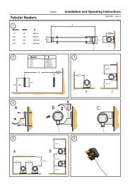
2.0 INSTALLATION<br />
2.1 Upon receipt, the controller should be visually inspected to check for any damage<br />
2.2 If there are any queries concerning the fan equipment, Elta Fans Ltd should be contacted prior to<br />
the installation.<br />
2.3 The controller must be securely mounted in the desired position to suit the application.<br />
2.4 The controller is only suitable for surface mounting and must not be recess mounted.<br />
2.5 Install in a dry sheltered position with a minimum clearance of 150mm above and below the<br />
controller to allow for adequate ventilation.
2.6 Do not install in close proximity to a heat source or in areas of high humidity. The maximum<br />
ambient temperature for the controller must not exceed 40º C (104º F).<br />
2.7 All electrical installation must be carried out by suitably qualified and competent personnel in<br />
accordance with all current statutory requirements.<br />
2.8 Check the details on the rating plate to ensure that the correct power supply (voltage, frequency<br />
and phase) is available. An incorrect power supply will lead to permanent damage of the unit.<br />
2.9 Check that the number, size and speed of the fan(s) can safely be controlled by the controller<br />
supplied.<br />
WARNING! The controller must be isolated from the power supply during installation and<br />
maintenance.<br />
2.10 Remove the front cover of the controller by unscrewing the cover fixing screws. This provides<br />
access to mounting holes and electrical terminals.<br />
2.11 These units are fitted with thermal overloads pre – set to your requirements.<br />
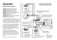
3.0 WIRING<br />
3.1 Select the correct wiring diagram for the fan and controller supplied. Ensure that all earth<br />
connections are made.<br />
3.2 All wiring and control equipment MUST comply with the latest IEE regulations, in particular 552-<br />
01-02/03.<br />
3.3 In the event that the wiring connections for the fan supplied do not correspond to diagrams<br />
shown, please refer to the fan instructions or contact ELTA FANS for further assistance.<br />
4.0 OPERATION FOR NON DUTY SHARE MODELS<br />
4.1 Switch on the electrical supply to the controller, select required fan via the two position rocker<br />
switch located on the front of the controller. In the event of the thermal overload tripping or<br />
airflow failure detected via the fans internally fitted air flow switches, the controller will<br />
automatically changeover to the standby fan, a fail light will be illuminated on the front panel.<br />
5.0 OPERATION FOR DUTY SHARE MODELS<br />
5.1 Switch on the electrical supply to the controller, select required fan via the two position rocker<br />
switch located on the front of the controller. In the event of the thermal overload tripping or<br />
airflow failure detected via the fans internally fitted air flow switches, the controller will<br />
automatically changeover to the standby fan, a fail light will be illuminated on the front panel.<br />
5.2 This product is not intended for use by persons (including children) with reduced physical,<br />
sensory or mental capabilities, or lack of experience and knowledge, unless they have been<br />
given supervision or instruction concerning use of the product by a person responsible for their<br />
safety.<br />
5.3 Children should be supervised to ensure that they do not play with the product.
WIRING<br />
GUARANTEE<br />
Elta Fans Ltd will, free of charge, within a period of 1 year from the date of despatch from their<br />
works, repair or at its option replace any goods which are proved to have defects as a result of<br />
defective materials or workmanship. The goods MUST be returned to Elta Fans Ltd carriage paid for<br />
examination.<br />
Elta Fans Ltd<br />
17 Barnes Wallis Road<br />
Segensworth East Industrial Estate<br />
Fareham, Hampshire, PO15 5ST, United Kingdom<br />
Visit: eltafans.com<br />
e-mail: mailbox@eltafans.co.uk<br />
Applied Technology: Tel: +44(0) 1489 566500 Fax: +44(0) 1489 566555<br />
Building Services: Tel: +44(0) 1384 275800 Fax: +44(0) 1384 275810<br />
Export: Tel: +44(0) 1489 566500 Fax: +44(0) 1489 566555<br />
<strong>ACO</strong>3/B Inst Issue 1: 30-11-07