installation instructions cuh heavy duty unit heater - LUCKINSlive
installation instructions cuh heavy duty unit heater - LUCKINSlive
installation instructions cuh heavy duty unit heater - LUCKINSlive

You also want an ePaper? Increase the reach of your titles
YUMPU automatically turns print PDFs into web optimized ePapers that Google loves.
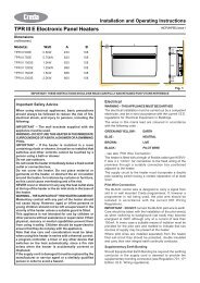
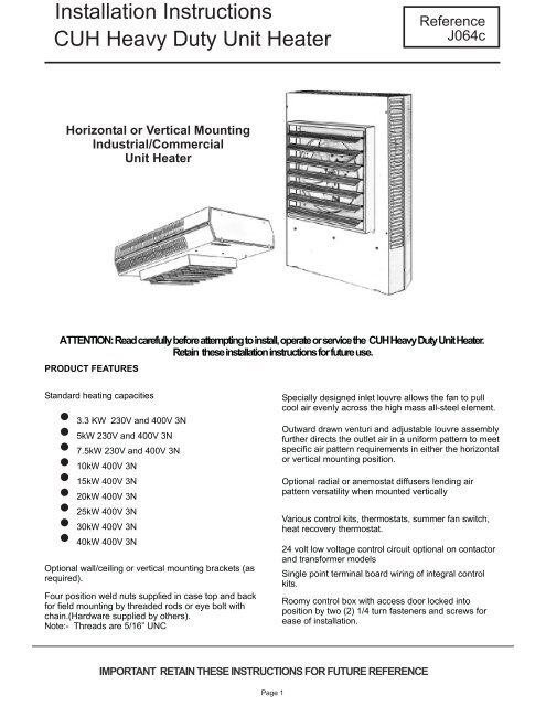
Installation InstructionsCUH Heavy Duty Unit HeaterReferenceJ064cHorizontal or Vertical MountingIndustrial/CommercialUnit HeaterATTENTION:Readcarefullybeforeattemptingtoinstall,operateorservicethe CUHHeavyDutyUnitHeater.Retain these<strong>installation</strong><strong>instructions</strong>forfutureuse.PRODUCT FEATURESStandard heating capacities3.3 KW 230V and 400V 3N5kW 230V and 400V 3N7.5kW 230V and 400V 3N10kW 400V 3N15kW 400V 3N20kW 400V 3N25kW 400V 3N30kW 400V 3N40kW 400V 3NOptional wall/ceiling or vertical mounting brackets (asrequired).Four position weld nuts supplied in case top and backfor field mounting by threaded rods or eye bolt withchain.(Hardware supplied by others).Note:- Threads are 5/16” UNCSpecially designed inlet louvre allows the fan to pullcool air evenly across the high mass all-steel element.Outward drawn venturi and adjustable louvre assemblyfurther directs the outlet air in a uniform pattern to meetspecific air pattern requirements in either the horizontalor vertical mounting position.Optional radial or anemostat diffusers lending airpattern versatility when mounted verticallyVarious control kits, thermostats, summer fan switch,heat recovery thermostat.24 volt low voltage control circuit optional on contactorand transformer modelsSingle point terminal board wiring of integral controlkits.Roomy control box with access door locked intoposition by two (2) 1/4 turn fasteners and screws forease of <strong>installation</strong>.IMPORTANT RETAIN THESE INSTRUCTIONS FORFUTUREREFERENCEPage 1
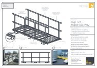
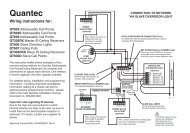
PROPER LOCATION INSTRUCTIONSOnce the total heating load is calculated, the quantityand capacity of the <strong>unit</strong> <strong>heater</strong>s must be determined. Alarge number of low-capacity <strong>heater</strong>s provides moreuniform heat distribution. This is recommended whenthe area will be occupied by a relatively large numberof sedentary personnel, (i.e. working on productionlines and at benches.)A large number of smaller capacity <strong>unit</strong> <strong>heater</strong>s tendsto prevent hot drafts, reduces noise levels, andincreases diversity of load to help reduce electricaldemand and operating costs.In warehouses where even heat distribution andconstant temperatures are less important, a smallernumber of high capacity <strong>unit</strong>s can be used -- in manycases reducing <strong>installation</strong> cost. To maintainreasonable heat distribution and reduce severestratification, even in lower bay areas, the total airvolume of the space should pass through the <strong>unit</strong><strong>heater</strong>s about three times per hour.It is important that the rated voltage of the heatingequipment matches the supply voltage. Supply voltagein excess of the <strong>heater</strong> rated voltage can damageequipment. Supply voltage lower than the rated <strong>heater</strong>voltage will decrease <strong>heater</strong> output as well as run therisk of damaging some components.Horizontal <strong>unit</strong> <strong>heater</strong>s are recommended in low bayareas with maximum 5 metre ceilings. These shouldbe concentrated along outside wall or other areas ofgreatest heat loss; spaced to set up a generallycircular air movement, each <strong>heater</strong> supporting the airstream of the other. Additional vertical down flow <strong>unit</strong><strong>heater</strong>s with appropriate accessory diffusers can belocated to counteract ceiling heat losses (see Figure 1Location charts).GENERAL SAFETY INFORMATION.The <strong>heater</strong>s should be installed in accordance with thelatest edition of BS7671 :2001 “Requirements forElectrical Installation”To avoid possible electrical shock, be sure theelectrical current is turned off at the main switch priorto wiring or servicing of <strong>unit</strong>.If the power disconnect is not integral and is out ofsight, lock it in the open position and tag to preventunexpected application of power prior to performingany service or maintenance of the <strong>unit</strong>.Make certain that the power source conforms to therequirement of your equipment.Check <strong>heater</strong> voltage and phase on rating label toconfirm that it matches the electric service supplyWiring diagrams of the <strong>heater</strong> and supply connectionsare permanently attached to the inside of the <strong>heater</strong>access door. All terminals are coded in accordancewith the wiring diagram. Accessory wiring is shown onthe <strong>unit</strong> wiring diagram and supporting literature..The <strong>heater</strong> must be mounted at least 2.2 metres abovethe floor to prevent accidental contact with the fanblade which could cause injury. Install <strong>unit</strong> so there areno obstructions to the intake or discharge. Maintainclearances as shown on Fig.1 & 2.The wall/ceiling mounting structure and anchoringprovisions must be of sufficient strength to support thecombined weight of the <strong>heater</strong> and mounting bracket.CONTROLOn/off control of the <strong>heater</strong> and controls such as timeclocks must be connected to the control circuit not themain supply. This is to allow the fan run on device tooperate when the <strong>heater</strong> has been switched off. The<strong>heater</strong> must NOT be switched by breaking the mainsupplyFigure 1 Location InstructionsHHHHHHHHHHVVHEXPOSEDHHHHEXPOSEDPage 2
PRINCIPLES OF OPERATIONUpon a call for heat from the remote low level oroptional <strong>unit</strong> mounted thermostat, the <strong>unit</strong> fan motorand heating elements will be energized and remainON until temperature reaches setting of thermostat; atwhich time the heating elements will be de-energized.The fan motor will continue to run and purge the<strong>heater</strong> casing of residual heat until the setting of fanoverride is reached, then the fan motor will be deenergized.For those <strong>unit</strong>s with a factory installed two speed fanswitch, the <strong>unit</strong> as shipped from the factory is set tolow speed. Customer option to set to high speed. Forthose <strong>unit</strong>s available with subdivided circuits, theoptional two stage thermostat will, upon a call forheat, energize fan motor and the first stage heatingelement. Should temperature continue to fall, thethermostat will energize the second stage heatingelement.Upon a rise in temperature towards the setting of thethermostat, the two stages of heating elements shallbe de-energized in reverse sequence.The fan motor shall continue to run and purge the<strong>heater</strong> casing of residual heat until setting of fanoverride is reached, then the fan motor will be deenergized.The optional <strong>unit</strong> mounted de-stratification thermostatwill energize the <strong>unit</strong> <strong>heater</strong> fan motor upon a rise intemperature above its setting.When the <strong>unit</strong> mounted stratification thermostat closeson a temperature rise and at the same time the floorthermostat calls for heat, the motor will be energizedimmediately and the heating element will be energized,as previously described.The automatic reset safety high limit shall de-energizethe heating elements and control circuits should thetemperature exceed the setting of this device. The fansafety override will energize the fan motor any time thesetting of this device is exceeded so as to purge <strong>heater</strong>casing of excess residual heat.When the fan switch is placed in the ON position (forsummer air circulation), the <strong>unit</strong> <strong>heater</strong> fan motor will beenergized.NOTE:The wall thermostat should be set to the OFFposition during this mode of operation (<strong>unit</strong>s withcontactors).For thermostats equipped with an integral fan switch,place the switch in the HEAT or AUTO position , foroperation of the fan and elements which will then beunder control of the thermostat as described above.When switch is placed in the OFF position, the <strong>unit</strong> willbe de-energized. When switch is placed in the FANposition, elements shall be de-energized and fan shallbe immediately energized.SPECIFICATIONHeaterFan motorAir VolMax Mtg Ht (m)ThrowWtCat No kW Volts Phase Amp/phWattrpmm3/hrHorizVertmkgsCUH-03-1CUH-03-3CCUH-05-1CUH-05-3CCUH-07-3CCUH-10-3CCUH-15-3CCUH-20-3CCUH-25-3CCUH-30-3CCUH-40-3C3.33.35.05.07.510.015.020.025.030.040.02304002304004004004004004004004001P3P&N1P3P&N3P&N3P&N3P&N3P&N3P&N3P&N3P&N13.44.520.56.810.213.620.427.234.040.854.46.06.06.06.015.015.038.062.062.062.0186.01550155015501550155015501550155015501550155068068068068011901190187034003400340052002.82.82.82.83.03.03.43.73.73.73.72.82.82.82.83.74.36.16.76.76.17.33.73.73.73.76.76.79.89.813.712.216.71212121223233055555555Page 3
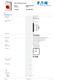
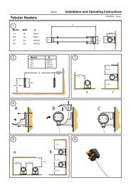
INSTALLATION INSTRUCTIONSCUH HEAVY DUTY UNIT HEATERAll electric <strong>unit</strong> <strong>heater</strong>s are shipped fully assembled.Installation includes hanging the <strong>unit</strong>, wiring of optionalcontrol devices and electrical wiring to the <strong>unit</strong>.To ensure proper delivery of the heated air to desiredareas, follow the mounting height tables included inthese <strong>instructions</strong>. See Fig. 1 & 2 for minimum walland ceiling clearances.Heaters may be mounted in the horizontal or verticalair discharge configuration using factory suppliedmounting equipment or using special hardwarefacilities supplied by others.The wall and/or ceiling structure must be sufficient tosupport the combined weight of the <strong>heater</strong> and anymounting bracket and accessories.FIG 1 HORIZONTAL DISCHARGEBe sure power source is de-energized before installing<strong>heater</strong>. The power supply must incorporate a means ofisolation having a contact separation of at least 3mm inall poles. Check <strong>heater</strong> voltage and phase listed onrating plate to make sure they are the same as theelectrical service supplied.Open the access panel and remove the desired knockout(s)on back of the <strong>unit</strong>.Install any optional accessories following their<strong>installation</strong> <strong>instructions</strong> before mounting <strong>unit</strong>. Followingthe correct <strong>unit</strong>/accessory wiring diagram, connect thepower supply electrical ground and accessories to thecorrect terminals or termination points using acceptedpractices.WARNING:- THE HEATER MUST BE EARTHEDAfter the <strong>installation</strong> is complete, replace the accesspanel. Set the controls (thermostat, switch, etc) at theirdesired control point and apply power to the <strong>unit</strong>.Check correct operation.DIMENSIONSABBDIMENSIONS (mm)FIG 2 VERTICAL DISCHARGEKW3.3 - 5.07.5 - 10.015.020.0 - 40.0H450620730865W368546546743D165165165256ABBAirflowHeaterBracketA mmB mmHorizontalVertical03 - 0507 - 1520 - 3003 - 05C35C720C2550VB3530045045030007 - 1520 - 30VB720V2550450450300600600300600600Page 4
INSTALLATION INSTRUCTIONSTASKMASTER -- 5100 SERIES UNIT HEATER (part 2)HORIZONTAL-- AIR DISCHARGE MOUNTINGCUH -C35, C720 and C2550 bracketsVERTICAL--AIRDISCHARGEMOUNTINGCUH -VB35 and VB720 bracketsSwivel hanger brackets may be used to suspend <strong>unit</strong><strong>heater</strong>s from either the wall (figure 5) or theceiling(figure 6). Attach hanger base (A) to top of<strong>heater</strong> with the four 5/16 X 18 caps screws andlockwashers provided.Attach main hanger frame (B) to wall or ceiling indesired location using suitable attachments (suppliedby others).Lift <strong>heater</strong> into position inserting stud (D) through holein main hanger frame and attach lock nut provided (E)tightening to within two turns of being tight.Swivel <strong>heater</strong> to desired position, tighten lock nut.Figure 5WALL MOUNTHORIZONTAL DISCHARGESecurely fix bracket rails to ceiling or structure atdesired height and location.- refer to . table for min / max dimensions and weights.The brackets are easiest to install with the <strong>heater</strong>mounting holes outermost, thus allowing tightening ofthe locknuts. They can be mounted the other way ifthis allows a more secure fixing.CUH 03 and 05 - The bracket rails can be mounted tothe <strong>unit</strong> either horizontally or vertically with fixing holecentres 334mm or 253mm respectively.CUH 07 and 10 - The bracket rails should be mountedhorizontally with fixing hole centres 458mm.CUH 15 - The bracket rails should be mountedhorizontally with fixing hole centres 570mmAssemble mounting studs, nuts and spring washers tothe four threaded inserts in rear of <strong>heater</strong> ensuring thestuds do not protrude more than 10mm inside thecase. Tighten nut against <strong>heater</strong>.Run second nuts approx 25mm down studs, put onplain washers.Locate studs in holes in bracket rails and secure withplain washers, spring washers and nuts.Adjust nuts to squarely locate <strong>heater</strong> without distortingthe <strong>heater</strong> body.Ensure all nuts are tight and fixings secure.Figure 6CEILING MOUNTHORIZONTAL DISCHARGECUH 20-40 - The CUH -V2550 bracket should be used- see <strong>instructions</strong> with bracket kitNOTE: When mounting <strong>heater</strong> using 5/16” UNC allthread rod (by others) do not screw the rod more than10mm beyond the inside of the case.SAFETYThe correct procedures for working at height must be adopted when installing this <strong>heater</strong>.CUH07 and larger <strong>unit</strong>s weigh over 20kgs and care should be taken with their handling.The <strong>heater</strong> must be installed by a suitably qualified person in accordance with current regulations.Page 5
5100 SERIES UNIT HEATERTROUBLE SHOOTING GUIDESYMPTOMThermostat calls forheat, but <strong>heater</strong> doesnot function.Fan motor runs HOTPOSSIBLE CAUSE(S)1. Open (blown) fuse2. INCORRECT WIRING3. Thermal cut-outopen, de-energizing <strong>heater</strong>element and control circuit.1. Dust accumulation orexcessive dirt on motor2. Dirt accumulation3. Motor needs lubrication.CORRECTIVE ACTION1. Replace fuses, check for cause.(see Replacement Parts List for fusesize)2. CHECK WIRING CONNECTIONS3. Check for the following:--- Correct supply volts and phase--- Correct control wiring (<strong>heater</strong>control must be thru thermostatcontrol wiring section only).--- Power interruption to <strong>heater</strong> during<strong>heater</strong> operation.--- Restriction of air around <strong>heater</strong> 1-5minute fan purge after thermostat off .1. Clean fan motor and casing of greaseand oil accumulation.2. . Clean louvers and between heatingelements.3. See Maintenance.Fan motor runs, butno heat.1. Element contactor notoperating correctly .2. Element fuse blown(if fitted).1. Check wiring for open circuit. Replacecontactor if defective2. Replace fuses, check for cause.MAINTENANCECAUTION: Make certain that the power source is disconnected before attempting to service or disassemble anycomponent. If the power disconnect is out of the line of sight, lock it in the OPEN position and tag to prevent theapplication of power.ELECTRICALOnce a year inspect the control panel wiring to make certain insulation is intact and all connections are tight.Inspect all <strong>heater</strong> and relay contacts. If the contacts appear badly pitted or burned, replace the contactor / relay .CLEANINGClean the <strong>unit</strong> casing, fan and motor once a year.A dirty motor will tend to run hot and eventually will bedamaged.internally. Any rust spots on the casing should be cleaned and repainted..LUBRICATIONAll <strong>unit</strong>s up to 15KW have fan motors that are permanently lubricated so that only occasional cleaning isrequired. Units above 15 KW have fan motors lubricated for 5 years of continuous <strong>duty</strong> of 10 years ofintermittent operations. When required, remove the oil access on plug back of <strong>heater</strong> at motor intake grill, openoil cap, fill with S.A.E. No.10 electric motor oil, replace plugs and access plug.Page 6
CUH HEAVY DUTY UNIT HEATERPARTS LIST - PART NUMBERSHEATER ELEMENT AUTOMATIC FAN XFMR CONTACTOR POWERMODEL MOTOR ASSEMBLY RESETCUT-OUTOVERRIDETERMINALBLOCKCUH-03-1 D010-01 B018-01 E036 E03556562-017 60715-002 57640-006 56811-001CUH-03-3C D01-01 B018-01 E036 E03556562-017 60715-002 57640-006 56811-001CUH-05-1 D010-01 B019-01 E036 E03556562-017 60715-006 57640-006 56811-001CUH-05-3C D010-01 B019-01 E036 E03556562-017 60715-006 57640-006 56811-001CUH-07-1C D011-01 B020-01 E037 E03556823-012 56954-006 57640-003 56811-001CUH-07-3C D011-01 B020-01 E037 E03556823-012 56954-006 57640-003 56811-001CUH-10-3C D011-01 1 B021-01 E037 E03556823-012 56953-004 57640-003 56811-001CUH-15-3C D012-01 B022-01 E038E03556825-002 56954-010 57640-004 56811-001CUH-20-3C(#4) D016-01 B074-01 E058 E04456943-002 56954-053 57640-005 56811-002CUH-25-3C D016-01 B048-01 E058 E044 E09856943-002 56954-018 57640-005 56811-002 60719-009CUH-30-3C D016-01 B049-01 E058 E044 E09856943-002 56954-021 57640-005 56811-002 60719-009CUH-40-3C D016-01 B050-01 E058 E044 E09856945-002 56954-024 57640-005 56811-002 60719-009E02350378-240E02350378-240E02350378-240E02350378-240E02350378-240E02350378-240E04058027-058E04058027-058E04058027-058F04356815-0012 x F0432 x 56815-001F04356815-0012 x F0432 x 56815-001F04356815-0012 x F0432 x 56815-0012 x F0432 x 56815-0012 x F0432 x 56815-0012 x F0432 x 56815-0012 x F0432 x 56815-0012 x F0432 x 56815-0012 x F0432 x 56815-001KW FAN TERMINAL GROUND MOTOR LOUVREBLADE BOARD CONN. CAPACITOR3.3 - 5 C007 56809-001 - (5) A035.56806-001 56809-001 1458 (5) 56986-0017.5 - 10 C003 56809-001 - (7) A03650551-002 56809-001 1458 (7) 56986-00315 C004 56809-001- (7) A03656813-001 56809-001 1458(7) 56986-00320 - 30 C005 56809-001 E054 (9) A03757114-001 56809-001 3981 57100-001 (9) 56987-00140 C006 56809-001 E054 (9) A03757115-001 56809-001 3981 57100-001 (9) 56987-001CONTROLCIRCUITAll sizesFUSEHOLDERE091FUSE(3A)E092Page 7
CUH HEAVY DUTY UNIT HEATERASSEMBLY DRAWINGWARRANTYThis product is guaranteed, in accordance with our Conditions of Sale, for a period of 12 months from date of purchase.We will repair or replace, at our discretion, any part found to be defective. We cannot accept responsibility for anyconsequential liability.The warranty will be invalid if the <strong>heater</strong> has not been installed in accordance with these <strong>instructions</strong>.This does not affect your statutory rights.The manufacturers reserve the right to change the specification at any time without prior notice E&OECommercial Electric Heat LimitedUnit 712Thorp Arch Trading EstateWETHERBYWest YorkshireLS23 7BJPage 8Tel 01937 844994 Fax 01937 844123email sales@cehltd.co.ukweb www.cehltd.co.uk