installation instructions cuh heavy duty unit heater - LUCKINSlive
installation instructions cuh heavy duty unit heater - LUCKINSlive
installation instructions cuh heavy duty unit heater - LUCKINSlive

You also want an ePaper? Increase the reach of your titles
YUMPU automatically turns print PDFs into web optimized ePapers that Google loves.
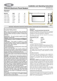
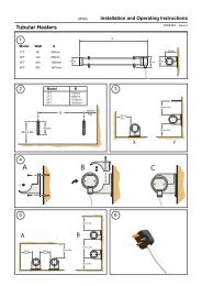
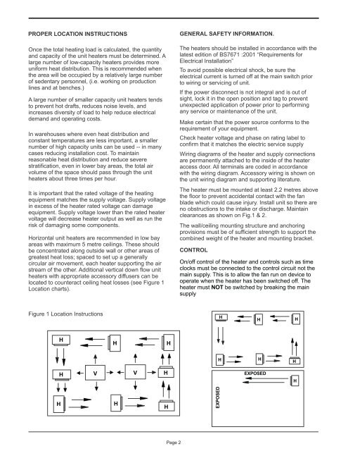
PROPER LOCATION INSTRUCTIONSOnce the total heating load is calculated, the quantityand capacity of the <strong>unit</strong> <strong>heater</strong>s must be determined. Alarge number of low-capacity <strong>heater</strong>s provides moreuniform heat distribution. This is recommended whenthe area will be occupied by a relatively large numberof sedentary personnel, (i.e. working on productionlines and at benches.)A large number of smaller capacity <strong>unit</strong> <strong>heater</strong>s tendsto prevent hot drafts, reduces noise levels, andincreases diversity of load to help reduce electricaldemand and operating costs.In warehouses where even heat distribution andconstant temperatures are less important, a smallernumber of high capacity <strong>unit</strong>s can be used -- in manycases reducing <strong>installation</strong> cost. To maintainreasonable heat distribution and reduce severestratification, even in lower bay areas, the total airvolume of the space should pass through the <strong>unit</strong><strong>heater</strong>s about three times per hour.It is important that the rated voltage of the heatingequipment matches the supply voltage. Supply voltagein excess of the <strong>heater</strong> rated voltage can damageequipment. Supply voltage lower than the rated <strong>heater</strong>voltage will decrease <strong>heater</strong> output as well as run therisk of damaging some components.Horizontal <strong>unit</strong> <strong>heater</strong>s are recommended in low bayareas with maximum 5 metre ceilings. These shouldbe concentrated along outside wall or other areas ofgreatest heat loss; spaced to set up a generallycircular air movement, each <strong>heater</strong> supporting the airstream of the other. Additional vertical down flow <strong>unit</strong><strong>heater</strong>s with appropriate accessory diffusers can belocated to counteract ceiling heat losses (see Figure 1Location charts).GENERAL SAFETY INFORMATION.The <strong>heater</strong>s should be installed in accordance with thelatest edition of BS7671 :2001 “Requirements forElectrical Installation”To avoid possible electrical shock, be sure theelectrical current is turned off at the main switch priorto wiring or servicing of <strong>unit</strong>.If the power disconnect is not integral and is out ofsight, lock it in the open position and tag to preventunexpected application of power prior to performingany service or maintenance of the <strong>unit</strong>.Make certain that the power source conforms to therequirement of your equipment.Check <strong>heater</strong> voltage and phase on rating label toconfirm that it matches the electric service supplyWiring diagrams of the <strong>heater</strong> and supply connectionsare permanently attached to the inside of the <strong>heater</strong>access door. All terminals are coded in accordancewith the wiring diagram. Accessory wiring is shown onthe <strong>unit</strong> wiring diagram and supporting literature..The <strong>heater</strong> must be mounted at least 2.2 metres abovethe floor to prevent accidental contact with the fanblade which could cause injury. Install <strong>unit</strong> so there areno obstructions to the intake or discharge. Maintainclearances as shown on Fig.1 & 2.The wall/ceiling mounting structure and anchoringprovisions must be of sufficient strength to support thecombined weight of the <strong>heater</strong> and mounting bracket.CONTROLOn/off control of the <strong>heater</strong> and controls such as timeclocks must be connected to the control circuit not themain supply. This is to allow the fan run on device tooperate when the <strong>heater</strong> has been switched off. The<strong>heater</strong> must NOT be switched by breaking the mainsupplyFigure 1 Location InstructionsHHHHHHHHHHVVHEXPOSEDHHHHEXPOSEDPage 2