MainswitchSurfacemounting Partno. T5B-4-15682/I4 ... - LUCKINSlive
MainswitchSurfacemounting Partno. T5B-4-15682/I4 ... - LUCKINSlive
MainswitchSurfacemounting Partno. T5B-4-15682/I4 ... - LUCKINSlive

Create successful ePaper yourself
Turn your PDF publications into a flip-book with our unique Google optimized e-Paper software.
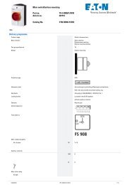
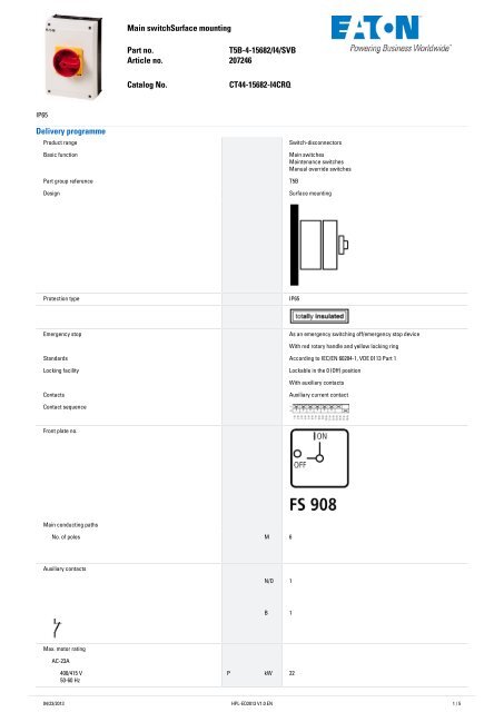
<strong>MainswitchSurfacemounting</strong><strong>Partno</strong>.<strong>T5B</strong>-4-<strong>15682</strong>/<strong>I4</strong>/SVBArticleno. 207246CatalogNo.CT44-<strong>15682</strong>-<strong>I4</strong>CRQIP65DeliveryprogrammeProduct range Switch-disconnectorsBasic function Main switchesMaintenance switchesManual override switchesPart group reference <strong>T5B</strong>Design Surface mountingProtection type IP65Emergency stop As an emergency switching off/emergency stop deviceWith red rotary handle and yellow locking ringStandards According to IEC/EN 60204-1, VDE 0113 Part 1Locking facility Lockable in the 0 (Off) positionWith auxiliary contactsContacts Auxiliary current contactContact sequenceFront plate no.Main conducting pathsNo. of poles M 6Auxiliary contactsN/O 1B 1Max. motor ratingAC-23A400/415 V50-60 HzP kW 2204/23/2013 HPL-ED2013 V1.0 EN 1 / 5
Rated uninterrupted current I u A 63ApprovalsProduct StandardsUL 508; CSA-C22.2 No. 14-05; IEC/EN 60947-3; CE markingUL File No.E36332UL CCNNLRV7CSA File No. 12528CSA Class No. 3211-05NA CertificationUL listed, CSA certifiedSpecially designed for NA Yes, in combination with "+NA-<strong>I4</strong>" (105868)Suitable forBranch circuits, suitable as motor disconnectDegree of Protection IEC: IP65; UL/CSA Type 1, 3R, 12, 13GeneralStandards IEC/EN 60947, VDE 0660, IEC/EN 60204, CSA, ULSwitch-disconnectors to IEC/EN 60947-3Load-break switches to IEC/EN 60947-3Lifespan, mechanical Operations x10 6 0.5Maximum operating frequency Operations/ 3000hClimatic proofing Damp heat, constant, to IEC 60068-2-78; Damp heat, cyclical, to IEC60068-2-30Ambient temperature °COpen °C - 25 - 50Enclosed °C - 25 - 40Mounting position As requiredMechanical shock resistance to IEC 60068-2-27ContactsHalfsinusoidalshock 20msRated operational voltage U e VACg > 15690Rated impulse withstand voltage U imp VAC6000Overvoltage category/pollution degree III/3Rated uninterrupted current I u Aopen I u A 63Enclosed I u A 63Load rating with intermittent operation, class 12AB 25 % DF x I e 2AB 40 % DF x I e 1.6AB 60 % DF x I e 1.3Short-circuit ratingFuse AgG/gL80Rated short-time withstand current (1 s current) I cw A rms 1300Safe isolation to EN 61140between the contacts VAC440Switching angles ° 90604530Contact units 10Double-break contacts max. 20Current heat loss per contact at I e W 4.5TerminalcapacitiesSolid or stranded 2mm 1 x (2.5 - 35)2 x (2.5 - 16)Flexible with ferrules to DIN 46228 mm 2Flexible with ferrule 2mm 1 x (1.5 - 25)2 x (1.5 - 10)Terminal screw M604/23/2013 HPL-ED2013 V1.0 EN 2 / 5
Tightening torque Nm 4SwitchingcapacityAC x U sRated making capacity cos ϕ = 0.35 A 800Rated breaking capacity, motor load switch cos ϕ = 0.35 A230 V A 520400 V A 600500 V A 480690 V A 340Rated operational current 440 V load-break switch AC-21A I e A 63Rating, AC-3 motor load switch P kW220 V 230 V P kW 15230 V Star-delta P kW 22380 V 400 V P kW 22400 V Star-delta P kW 37500 V P kW 22500 V Star-delta P kW 37660 V 690 V P kW 22690 V Star-delta P kW 37AC-23A Motor load switches (main switches maintenance switches) P kW230 V P kW 15400 V P kW 22500 V P kW 22690 V P kW 22Rated operational current control switch AC-15220 V 230 V 240 V I e A 16380 V 400 V 415 V I e A 6500 V I e A 4DC x U sDC-1, Load-break switches L/R = 1 msRated operational current I e A 63Voltage per contact pair in series V 60DC-23A, motor load switch L/R = 15 ms24 V48 V60 V120 V240 VRated operational current I e A 50Contacts Quantity 1Rated operational current I e A 50Contacts Quantity 2Rated operational current I e A 50Contacts Quantity 3Rated operational current I e A 25Contacts Quantity 3Rated operational current I e A 20Contacts Quantity 6DC-13, Control switches L/R = 50 msRated operational current I e A 25Voltage per contact pair in series V 24Control circuit reliability at 24 V DC, 10 mAAuxiliarycontactsFaultprobabilityH F< 10-5 , < 1 fault in 100000 operationsStandards According to IEC/EN 60204-1, VDE 0113 Part 104/23/2013 HPL-ED2013 V1.0 EN 3 / 5
NotesNotesThe following applies for solid, multiwire, and flexible terminal capacities:If 2 conductors are being used, a max. difference of one cross-section category is permissibleThe following applies for part no. T8-3-8342/...: switching angle = 90° and flat terminal = 1 rail, 25 x 5, or 2 rails, 20 x 3TechnicaldataETIM4.0Version as switch disconnector compact NoVersion as main switch YesVersion as maintenance-/service switch YesVersion as safety switch NoVersion as emergency stop installation YesMax. rated operation voltage Ue AC V 690Rated permanent current Iu A 63Rated operation power AC-3, 400 V kW 22Rated operation power at AC-23, 400V kW 22Conditioned rated short-circuit current Iq kA 0Number of poles 6Number of auxiliary contacts as normally closed contact 1Number of auxiliary contacts as normally open contact 1Number of auxiliary contacts as change-over contact 0Motor drive optional NoMotor drive integrated NoVoltage release optional NoDevice construction Complete device in housingSuitable for ground mounting YesSuitable for front mounting NoSuitable for front mounting center NoSuitable for distribution board installation NoSuitable for intermediate mounting NoType of control element -Interlockable YesConnection type main current circuit Screw connectionDegree of protection (IP), front side IP65CharacteristicsFor utilisation category AC-4 (extreme load: 100 % inching, reversing or plugging)The blocked rotor current of the motor should not exceed the rated current of the switch for AC-21A to ensure a reasonable device lifespan.Dimensions04/23/2013 HPL-ED2013 V1.0 EN 4 / 5
Depth of one contact unit: 16.5 mmThe rotary switches <strong>T5B</strong> and T5 are of identical design but differ in their contacts.3 padlocksAdditionalproductinformation(links)IL03801009Z(AWA1150-1692)Camswitch:switch-disconnectorIL03801009Z (AWA1150-1692) Camswitch: switch-disconnectorftp://ftp.moeller.net/DOCUMENTATION/AWA_INSTRUCTIONS/IL03801009Z2011_06.pdfhttp://ecat.moeller.net/flip-cat/?edition=HPLEN&startpage=4.87http://ecat.moeller.net/flip-cat/?edition=K115A&startpage=4104/23/2013 Eaton Industries GmbHhttp://www.eaton.eu© 04/2013 by Eaton Industries GmbHHPL-ED2013 V1.0 EN5 / 5