KWH102KQ03-F02 - Display Future
KWH102KQ03-F02 - Display Future
KWH102KQ03-F02 - Display Future

You also want an ePaper? Increase the reach of your titles
YUMPU automatically turns print PDFs into web optimized ePapers that Google loves.
FORMIKE ELECTRONIC CO.,LTD<br />
PRDUCT SPECIFICATON<br />
TFT LCD MODULE<br />
MODEL : <strong>KWH102KQ03</strong>-<strong>F02</strong><br />
【 】 Preliminary Specification<br />
【 ◆ 】 Finally Specification<br />
CUSTOMER'S APPROVAL<br />
SIGNATURE:<br />
DATE:<br />
APPROVED PM PD PREPARED<br />
BY REVIEWD REVIEWD BY<br />
Wayne Li tong Zhengjinrong Jully<br />
Prepared By :<br />
FORMIKE ELECTRONIC CO.,LTD<br />
Address : A909, Huaying Building, 97 Nanshang Road,Nanshan District, Shenzhen, China.518054<br />
TEL:(86) 755 88306921,88306931 FAX:(86) 755 88304615<br />
Http:// www.wandisplay.com<br />
● This specification is subject to change withouth notice.Please contact FORMIKE or it's<br />
representative before designing your product based on this specification.<br />
Issued Date: Mar-15-2007
Formike Electronic Co.,Ltd.<br />
Issued Date : 2007-03-05<br />
MODEL NO :<strong>KWH102KQ03</strong>-<strong>F02</strong><br />
Contents:<br />
1. General Specifications...........................................................................................................2<br />
2. Pin Assignment......................................................................................................................3<br />
2.1. TFT LCD Panel Driving Section.....................................................................................3<br />
2.2. Backlight Unit Section....................................................................................................7<br />
3. Operation Specifications .........................................................................................................8<br />
3.1. Absolute Maximum Rating ..............................................................................................8<br />
3.1.1 Typical Operation Conditions.................................................................................8<br />
3.1.2 Current Consumption ............................................................................................9<br />
3.1.3 Backlight Driving Conditions.................................................................................10<br />
3.2 Power Sequence ..........................................................................................................11<br />
3.3 Timing Characteristics .................................................................................................. 12<br />
3.3.1 Timing Conditions................................................................................................. 13<br />
3.3.2 Timing Diagram .................................................................................................. .14<br />
4. Optical Specifications............................................................................................................21<br />
5. Reliability Test Items.............................................................................................................25<br />
6. General Precautions.............................................................................................................26<br />
6.1 Safety ...........................................................................................................................27<br />
6.2 Handling .......................................................................................................................27<br />
6.3 Static Electricity ............................................................................................................27<br />
6.4 Storage .........................................................................................................................27<br />
6.5 Cleaning .......................................................................................................................27<br />
7 Mechanical Drawing .............................................................................................................28<br />
8 Package Drawing .................................................................................................................29<br />
8.1 Packaging Material Table..............................................................................................29<br />
8.2 Packaging Quantity ......................................................................................................29<br />
-1-
Formike Electronic Co.,Ltd.<br />
Issued Date : 2007-03-05<br />
MODEL NO :<strong>KWH102KQ03</strong>-<strong>F02</strong><br />
1. General Specifications<br />
No. Item Specification Remark<br />
1 LCD size 10.2 inch(Diagonal)<br />
2 Driver element a-Si TFT active matrix<br />
3 Resolution 800X3(RGB)X480<br />
4 <strong>Display</strong> mode Normally white, Transmissive<br />
5 Dot pitch 0.0925(W)X0.276(H) mm<br />
6 Active area 222.0(W)X132.48(H) mm<br />
7 Module size 235.0(W)X145.8(H)X7.6(D) mm Note 1<br />
8 Surface treatment Anti-Glare<br />
9 Color arrangement RGB-stripe<br />
10 Interface Digital<br />
11 Backlight power consumption 2.57W(Typ.)<br />
12 Panel power consumption 250mW(Typ.)<br />
13 Weight 385g(Typ.)<br />
Note 1: Refer to Mechanical Drawing.<br />
-2-
Formike Electronic Co.,Ltd.<br />
Issued Date : 2007-03-05<br />
MODEL NO :<strong>KWH102KQ03</strong>-<strong>F02</strong><br />
2. Pin Assignment<br />
2.1a.<br />
TFT LCD Panel Driving Section<br />
FPC connector is used for the module electronics interface. The recommended model is<br />
“AF 730L-A2G1T” manufactured by P-TWO.<br />
Pin No. Symbol I/O Function Remark<br />
1 POL I Polarity selection<br />
2 STVD I/O Vertical start pulse input when U/D= H Note 1<br />
3 OEV I Output enable<br />
4 CKV I Vertical clock<br />
5 STVU I/O Vertical start pulse input when U/D= L Note 1<br />
6 GND P Power ground<br />
7 EDGSL I Select rising edge or rising/falling edge<br />
8 V CC P Power supply for digital circuit<br />
9 V9 I Gamma voltage level 9<br />
10 V GL P Gate OFF voltage<br />
11 V2 I Gamma voltage level 2<br />
12 V GH P Gate ON voltage<br />
13 V6 I Gamma voltage level 6<br />
14 U/D I Up/down selection Note 1,2<br />
15 V COM I Common voltage<br />
16 GND P Power ground<br />
17 AV DD P Power supply for analog circuit<br />
18 V14 I Gamma voltage level 14<br />
19 V11 I Gamma voltage level 11<br />
20 V8 I Gamma voltage level 8<br />
-3-
Formike Electronic Co.,Ltd.<br />
Issued Date : 2007-03-05<br />
MODEL NO :<strong>KWH102KQ03</strong>-<strong>F02</strong><br />
21 V5 I Gamma voltage level 5<br />
22 V3 I Gamma voltage level 3<br />
23 GND P Power ground<br />
24 R5 I Red data(MSB)<br />
25 R4 I Red data<br />
26 R3 I Red data<br />
27 R2 I Red data<br />
28 R1 I Red data<br />
29 R0 I Red data(LSB)<br />
30 GND P Power ground<br />
31 GND P Power ground<br />
32 G5 I Green data(MSB)<br />
33 G4 I Green data<br />
34 G3 I Green data<br />
35 G2 I Green data<br />
36 G1 I Green data<br />
37 G0 I Green data(LSB)<br />
38 STHL I/O<br />
Horizontal start pulse input when R/L =<br />
L<br />
Note 1<br />
39 REV P Control signal are inverted or not Note 3<br />
40 GND I Power ground<br />
41 DCLK I Sample clock<br />
42 DV DD P Voltage for digital circuit<br />
43 STHR I/O<br />
44 LD I<br />
45 B5 I Blue data (MSB)<br />
Horizontal start pulse input when R/L =<br />
H<br />
Latches the polarity of outputs and<br />
switches the new data to outputs<br />
Note 1<br />
-4-
Formike Electronic Co.,Ltd.<br />
Issued Date : 2007-03-05<br />
MODEL NO :<strong>KWH102KQ03</strong>-<strong>F02</strong><br />
46 B4 I Blue data<br />
47 B3 I Blue data<br />
48 B2 I Blue data<br />
49 B1 I Blue data<br />
50 B0 I Blue data (LSB)<br />
51 R/L I Right/ left selection Note 1,2<br />
52 V1 I Gamma voltage level 1<br />
53 V4 I Gamma voltage level 4<br />
54 V7 I Gamma voltage level 7<br />
55 V10 I Gamma voltage level 10<br />
56 V12 I Gamma voltage level 12<br />
57 V13 I Gamma voltage level 13<br />
58 AV DD P Voltage for analog circuit<br />
59 GND P Power ground<br />
60 V COM I Common voltage<br />
I: input, O: output, P: Power<br />
Note 1: Selection of scanning mode<br />
2.1b. TP PIN<br />
Setting of scan<br />
control input<br />
IN/OUT state for start pulse<br />
U/D R/L STVD STVU STHR STHL<br />
Scanning direction<br />
GND V CC O I I O Up to down, left to right<br />
V CC GND I O O I Down to up, right to left<br />
GND GND O I O I Up to down, right to left<br />
V CC V CC I O I O Down to up, left to right<br />
-5-
Formike Electronic Co.,Ltd.<br />
Issued Date : 2007-03-05<br />
MODEL NO :<strong>KWH102KQ03</strong>-<strong>F02</strong><br />
Note 2: Definition of scanning direction.<br />
Refer to the figure as below:<br />
Up<br />
Left<br />
Right<br />
Bottom<br />
Note 3: When REV=”L” , normally<br />
REV=”H”, these data will be inverted.<br />
-6-
Formike Electronic Co.,Ltd.<br />
Issued Date : 2007-03-05<br />
MODEL NO :<strong>KWH102KQ03</strong>-<strong>F02</strong><br />
2.2. Backlight Unit Section<br />
CCFL connector is used for the the integral backlight system. The recommended<br />
model is “BHSR-02VS-1” manufactured by JST.<br />
Pin No. Symbol I/O Function Remark<br />
1 HI P Power supply for backlight unit Pink<br />
2 GND P Ground for backlight unit White<br />
-7-
Formike Electronic Co.,Ltd.<br />
Issued Date : 2007-03-05<br />
MODEL NO :<strong>KWH102KQ03</strong>-<strong>F02</strong><br />
3. Operation Specifications<br />
3.1. Absolute Maximum Rating<br />
(GND=AV SS =0V, Note 2)<br />
Item<br />
Symbol<br />
Min.<br />
Values<br />
Max.<br />
Unit<br />
Remark<br />
V CC -0.3 5 V<br />
AV DD -0.5 12 V<br />
Power voltage<br />
V GH -0.3 18 V<br />
V GL -15 0.3 V<br />
V GH -V GL - 33 V<br />
Input signal voltage<br />
V1~V7 0.4 AV DD AV DD -0.1 V Note 1<br />
V8~V14 -0.3 0.6AV DD V<br />
Operation temperature T OP -30 85 ℃<br />
Storage temperature T ST -30 85 ℃<br />
LED Reverse Voltage Vr - 1.2 V<br />
Each LED<br />
Note 3<br />
LED Forward Current I f - 25 mA Each LED<br />
Note 1: AVDD - 0.1≧V1≧V2≧V3≧V4≧V5≧V6≧V7≧V8≧V9≧V10>V11≧V12≧<br />
V13≧V14≧AVSS + 0.1<br />
Note 2: The absolute maximum rating values of the module should not be exceeded. Once<br />
exceeded absolute maximum rating values, the characteristics of the module may<br />
not be recovered. Even in an extreme condition, may result in module permanently<br />
destroyed.<br />
Note 3: Vr conditions: Zener Diode 20mA.<br />
-8-
Formike Electronic Co.,Ltd.<br />
Issued Date : 2007-03-05<br />
MODEL NO :<strong>KWH102KQ03</strong>-<strong>F02</strong><br />
3.1.1 Typical Operation Conditions<br />
(GND=AV SS =0V, Note 1)<br />
Item<br />
Symbol<br />
Values<br />
Min. Typ. Max.<br />
Unit<br />
Remark<br />
V CC 3.0 3.3 3.6 V<br />
Power voltage<br />
AV DD 9.0 9.2 9.4 V<br />
V GH 14.3 15 15.7 V<br />
V GL -10.5 -10 -9.5 V<br />
V COM 3.5 3.7 3.9 V<br />
(V1+V14)/2<br />
=4.5V<br />
Input signal voltage<br />
V1~V7 0.4 A VDD - A VDD -0.1 V<br />
V8~V14 0.1 - 0.6 A VDD V<br />
Input logic high voltage V IH 0.7V CC - V CC V<br />
Input logic low voltage V IL 0 - 0.3V CC V<br />
Note 1: Be sure to apply GND, V CC , and V GL , to the LCD first, and then apply V GH .<br />
-9-
Issued Date : 2007-03-05<br />
Formike Electronic Co.,Ltd. MODEL NO :<strong>KWH102KQ03</strong>-<strong>F02</strong><br />
3.1.2 Current Consumption<br />
(GND=AV SS =0V)<br />
Values<br />
Item<br />
Symbol<br />
Unit Remark<br />
Min. Typ. Max.<br />
I GH - 0.3 0.5 mA V GH =15V<br />
I GL - 0.2 1.0 mA V GL = -10V<br />
Current for Driver<br />
I CC - 4 10 mA V CC =3.3V<br />
I DD - 25 50 mA AV DD =9.2V<br />
3.1.3 Backlight Driving Conditions<br />
Values<br />
Item<br />
Symbol<br />
Unit Remark<br />
Min. Typ. Max.<br />
LED forward voltage V L 9.3 9.9 10.5 V Note 2, 3<br />
LED forward current I L 18 20 22 mA Note 3<br />
LED life time - 20,000 - - Hr Note 1<br />
Note 1: The “LED life time” is defined as the module brightness decrease to 50% original<br />
brightness at Ta=25℃ and I L =20mA. The LED lifetime could be decreased if<br />
operating I L is larger than 20 mA.<br />
Note 2: The LED Supply Voltage is defined by the number of LED at Ta=25℃ and<br />
I L =20mA. In the case of 3pcs LED, V L =3.3*3=9.9V<br />
Note 3: The LED driving condition is defined for each LED module.( 3 LED Serial)<br />
LED 1<br />
I L<br />
LED 2<br />
V L<br />
I L<br />
I L* 13<br />
LED 12<br />
I L<br />
LED 13<br />
-10-
Formike Electronic Co.,Ltd.<br />
Issued Date : 2007-03-05<br />
MODEL NO :<strong>KWH102KQ03</strong>-<strong>F02</strong><br />
3.2 Power Sequence<br />
3.2.1 Power on:<br />
20ms<br />
10ms<br />
VGH<br />
B/L<br />
AVDD<br />
VCC<br />
DATA<br />
T=0<br />
5ms<br />
GND<br />
10ms<br />
VGL<br />
T<br />
3.2.2 Power off:<br />
VCC→VGL→VGH→Data→B/L<br />
VGH<br />
B/L<br />
AVDD<br />
VCC<br />
DATA<br />
10ms<br />
20ms<br />
T=0<br />
GND<br />
5ms<br />
10ms<br />
VGL<br />
B/L→Data→VGH→VGL→VCC<br />
Note: Data includes POL, STVD, OEV, CKV, STVU, EDGSL, STHL, REV, DCLK, DV DD ,<br />
STHR, LD.<br />
T<br />
-11-
Formike Electronic Co.,Ltd.<br />
Issued Date : 2007-03-05<br />
MODEL NO :<strong>KWH102KQ03</strong>-<strong>F02</strong><br />
3.3 Timing Characteristics<br />
3.3.1 Timing Conditions<br />
Item<br />
Symbol<br />
Values<br />
Min. Typ. Max.<br />
Unit<br />
Remark<br />
DCLK frequency F dclk - 40 45 MHz<br />
DCLK cycle T cph 22 25 - ns<br />
DCLK pulse width T cw 8 - - ns<br />
Data set-up time T su 4 - - ns<br />
Data hold time T hd 2 - - ns<br />
Time that the last data to LD T ld 1 - - Tcph<br />
Pulse width of LD T wld 2 - - Tcph<br />
Time that LD to STHL/R T lds 5 - - Tcph<br />
POL set-up time T psu 6 - - ns<br />
POL hold time T phd 6 - - ns<br />
CKV frequency F vclk - - 200 KHz<br />
CKV rise time T rck - - 100 ns<br />
CKV falling time T fck - - 100 ns<br />
CKV pulse width P WCLK 500 - - ns<br />
Horizontal display timing range T dh - 800 - Tcph<br />
Horizontal timing range T h - 1056 - Tcph<br />
STVU/D setup time T suv 200 - - ns<br />
STVU/D hold time T hdv 300 - - ns<br />
STVU/D delay time T dt - - 500 ns<br />
Driver output delay time T do - - 900 ns<br />
-12-
Formike Electronic Co.,Ltd.<br />
Issued Date : 2007-03-05<br />
MODEL NO :<strong>KWH102KQ03</strong>-<strong>F02</strong><br />
Output rise time T tlh - 500 1000 ns<br />
Output falling time T thl - 400 800 ns<br />
OEV pulse width T wcl 1 - - us<br />
OEV to Driver output delay time T oe - - 900 ns<br />
Horizontal lines per field T v 512 525 610 Tdh<br />
Vertical display timing range T vd - 480 - Tdh<br />
-13-
Formike Electronic Co.,Ltd.<br />
Issued Date : 2007-03-05<br />
MODEL NO :<strong>KWH102KQ03</strong>-<strong>F02</strong><br />
3.3.2 Timing Diagram<br />
Timing Diagram1 (CHNSL="1" , Default)<br />
<br />
DCLK<br />
Tcph<br />
70%<br />
70%<br />
70%<br />
2<br />
70%<br />
799<br />
70%<br />
1<br />
800<br />
30%<br />
30%<br />
Tsu Thd Tcw Tcw<br />
STHL/R<br />
(input)<br />
70% 70%<br />
Tsu Thd<br />
Date RGB<br />
70%<br />
First data Second data Last data<br />
Tphl Tphl<br />
STHR/L<br />
(output)<br />
70%<br />
30%<br />
Fig.3-1 operation model 1<br />
-14-
Formike Electronic Co.,Ltd.<br />
Issued Date : 2007-03-05<br />
MODEL NO :<strong>KWH102KQ03</strong>-<strong>F02</strong><br />
< EDGSL ="1"><br />
DCLK<br />
70%<br />
70%<br />
1<br />
2<br />
30%<br />
30%<br />
Tsu Thd Tcw Tcw<br />
STHL/R<br />
70% 70%<br />
(input)<br />
Tsu Thd<br />
Data<br />
RGB<br />
70% 70%<br />
First data Second<br />
data<br />
STHR/L<br />
(output)<br />
Fig.3-2 operation model 2<br />
70%<br />
799<br />
Tphl<br />
70%<br />
70%<br />
800<br />
30%<br />
Tsu Thd<br />
70%<br />
Last<br />
data<br />
30% 30%<br />
Tphl<br />
30%<br />
-15-
Formike Electronic Co.,Ltd.<br />
Issued Date : 2007-03-05<br />
MODEL NO :<strong>KWH102KQ03</strong>-<strong>F02</strong><br />
Timing Diagram 2<br />
DCLK<br />
70%<br />
Last<br />
LD<br />
Tld<br />
70% Twld 70%<br />
STHL/R<br />
(input)<br />
Tlds<br />
70%<br />
LD<br />
70%<br />
70%<br />
30%<br />
30%<br />
Tpsu Tphd TpsuTphd<br />
POL<br />
70%<br />
70%<br />
Odd<br />
outputs<br />
Even<br />
outputs<br />
High-Z<br />
Tst<br />
10%<br />
90%<br />
High-Z<br />
Tst<br />
90%<br />
10%<br />
Fig.3-3 Horizontal timing 1<br />
70%<br />
70%<br />
Tpsu Tphd<br />
High-Z<br />
30%<br />
Positive<br />
Tst<br />
Negative<br />
-16-
Formike Electronic Co.,Ltd.<br />
Issued Date : 2007-03-05<br />
MODEL NO :<strong>KWH102KQ03</strong>-<strong>F02</strong><br />
Th<br />
Hs<br />
DCLK<br />
RGB 1 2 3 798799 800<br />
Tdh<br />
DE<br />
Fig.3-4 Horizontal timing 2<br />
-17-
Formike Electronic Co.,Ltd.<br />
Issued Date : 2007-03-05<br />
MODEL NO :<strong>KWH102KQ03</strong>-<strong>F02</strong><br />
Fig.3-5 Vertical shift clock timing<br />
-18-
Formike Electronic Co.,Ltd.<br />
Issued Date : 2007-03-05<br />
MODEL NO :<strong>KWH102KQ03</strong>-<strong>F02</strong><br />
Fig.3-6 Vertical timing (from up to down)<br />
-19-
Formike Electronic Co.,Ltd.<br />
Issued Date : 2007-03-05<br />
MODEL NO :<strong>KWH102KQ03</strong>-<strong>F02</strong><br />
Tv<br />
Vs<br />
DE<br />
Tvd<br />
RGB 1 2 3 478479 480<br />
Fig.3-7 Vertical timing<br />
-20-
Formike Electronic Co.,Ltd.<br />
Issued Date : 2007-03-05<br />
MODEL NO :<strong>KWH102KQ03</strong>-<strong>F02</strong><br />
4. Optical Specifications<br />
Item Symbol Condition<br />
Values<br />
Min. Typ. Max.<br />
Unit<br />
Remark<br />
Viewing angle<br />
(CR≥10)<br />
θ L Φ=180°(9 o’clock) 55 65 -<br />
θ R Φ=0°(3 o’clock) 55 65 -<br />
θ T Φ=90°(12 o’clock) 35 45 -<br />
θ B Φ=270°(6 o’clock) 55 65 -<br />
degree Note 1<br />
Response time<br />
T ON - 15 30 msec Note 3<br />
T OFF - 20 40 msec Note 3<br />
Contrast ratio CR 250 300 - - Note 4<br />
Color chromaticity<br />
W X<br />
Normal<br />
θ=Φ=0°<br />
0.26 0.31 0.36 -<br />
W Y 0.28 0.33 0.38 -<br />
Note 5<br />
Note 6<br />
Luminance L 200 250 - cd/m² Note 6<br />
Luminance uniformity Y U<br />
70 75 - - Note 7<br />
Test Conditions:<br />
1. V CC =3.3V, AV DD =12V, I L* 13=260mArms (Backlight current), the ambient temperature<br />
is 25 ℃ .<br />
2. The test systems refer to Note 2.<br />
-21-
Formike Electronic Co.,Ltd.<br />
Issued Date : 2007-03-05<br />
MODEL NO :<strong>KWH102KQ03</strong>-<strong>F02</strong><br />
Note 1: Definition of viewing angle range<br />
Normal line<br />
θ=Φ=0°<br />
Φ=90°<br />
12 o’clock direction<br />
θ L<br />
θ T θ R<br />
Φ=180°<br />
θ B<br />
Active Area<br />
Φ=0°<br />
Φ=270°<br />
6 o’clock direction<br />
Fig. 4-1 Definition of viewing angle<br />
Note 2: Definition of optical measurement system.<br />
The optical characteristics should be measured in dark room. After 30 minutes<br />
operation, the optical properties are measured at the center point of the LCD screen.<br />
(Response time is measured by Photo detector TOPCON BM-7, other items are<br />
measured by BM-5A/Field of view: 1° /Height: 500mm.)<br />
Photo detector<br />
Normal line<br />
θ=Φ=0°<br />
500mm<br />
Φ=90°<br />
12 o’clock direction<br />
Φ=180°<br />
Active Area<br />
Φ=0°<br />
LCD Panel<br />
Φ=270°<br />
6 o’clock direction<br />
Fig. 4-2 Optical measurement system setup<br />
-22-
Formike Electronic Co.,Ltd.<br />
Issued Date : 2007-03-05<br />
MODEL NO :<strong>KWH102KQ03</strong>-<strong>F02</strong><br />
Note 3: Definition of Response time<br />
The response time is defined as the LCD optical switching time interval between<br />
“White” state and “Black” state. Rise time (T ON ) is the time between photo detector output<br />
intensity changed from 90% to 10%. And fall time (T OFF ) is the time between photo<br />
detector output intensity changed from 10% to 90%.<br />
White (TFT OFF) Black (TFT ON) White (TFT OFF)<br />
Photo detector output<br />
(Relative value)<br />
100%<br />
90%<br />
10%<br />
0%<br />
T ON<br />
T OFF<br />
Fig. 4-3 Definition of response time<br />
Note 4: Definition of contrast ratio<br />
Luminance measured when LCD on the " White" state<br />
Contrast ratio (CR) =<br />
Luminance measured when LCD on the "Black" state<br />
Note 5: Definition of color chromaticity (CIE1931)<br />
Color coordinates measured at center point of LCD.<br />
Note 6: All input terminals LCD panel must be ground when measuring the center area of<br />
the panel.<br />
-23-
Formike Electronic Co.,Ltd.<br />
Issued Date : 2007-03-05<br />
MODEL NO :<strong>KWH102KQ03</strong>-<strong>F02</strong><br />
Note 7: Definition of Luminance Uniformity<br />
Active area is divided into 9 measuring areas (Refer to Fig. 4-4 ).Every<br />
measuring point is placed at the center of each measuring area.<br />
Bmin<br />
Luminance Uniformity (Yu) =<br />
Bmax<br />
L-------Active area length W----- Active area width<br />
W<br />
W/3 W/3 W/6<br />
L/6<br />
L/3<br />
L<br />
L/3<br />
Fig. 4-4 Definition of measuring points<br />
B max : The measured maximum luminance of all measurement position.<br />
B min : The measured minimum luminance of all measurement position.<br />
-24-
Formike Electronic Co.,Ltd.<br />
Issued Date : 2007-03-05<br />
MODEL NO :<strong>KWH102KQ03</strong>-<strong>F02</strong><br />
5. Reliability Test Items<br />
(Note3)<br />
Item Test Conditions Remark<br />
High Temperature Storage Ta = 85 ℃ 240 hrs<br />
Note 1,Note 4<br />
Low Temperature Storage Ta = -30 ℃ 240hrs<br />
Note 1,Note 4<br />
High Temperature Operation Ts = 85 ℃ 240hrs<br />
Note 2,Note 4<br />
Low Temperature Operation Ta = -30 ℃ 240hrs<br />
Note 1,Note 4<br />
Operate at High Temperature<br />
and Humidity<br />
+60 ℃ , 90%RH<br />
240 hrs Note 4<br />
Thermal Shock<br />
Vibration Test<br />
Mechanical Shock<br />
Package Vibration Test<br />
Package Drop Test<br />
Electro Static Discharge<br />
-30 ℃ /30 min ~ +85 ℃ /30 min for a total 100<br />
cycles, Start with cold temperature and end<br />
with high temperature<br />
Frequency range:10~55Hz<br />
Stroke:1.5mm<br />
Sweep:10Hz~55Hz~10Hz<br />
2 hours for each direction of X. Y. Z.<br />
(6 hours for total)<br />
100G 6ms,±X, ±Y, ±Z 3 times for each<br />
direction<br />
Random Vibration :<br />
0.015G*G/Hz from 5-200HZ, -6dB/Octave<br />
from 200-500HZ<br />
2 hours for each direction of X. Y. Z.<br />
(6 hours for total)<br />
Height:60 cm<br />
1 corner, 3 edges, 6 surfaces<br />
± 2KV, Human Body Mode, 100pF/1500Ω<br />
Note 4<br />
Note 1: Ta is the ambient temperature of samples.<br />
Note 2: Ts is the temperature of panel’s surface.<br />
Note 3: In the standard condition, there shall be no practical problem that may<br />
affect the display function. After the reliability test, the product only guarantees<br />
operation, but doesn't guarantee all the cosmetic specification.<br />
Note 4: Before cosmetic and function tests, the product must have enough recovery time,<br />
at least 2 hours at room temperature.<br />
-25-
Formike Electronic Co.,Ltd.<br />
Issued Date : 2007-03-05<br />
MODEL NO :<strong>KWH102KQ03</strong>-<strong>F02</strong><br />
6. General Precautions<br />
6.1 Safety<br />
Liquid crystal is poisonous. Do not put it in your mouth. If liquid crystal touches your<br />
skin or clothes, wash it off immediately by using soap and water.<br />
6.2 Handling<br />
1. The LCD panel is plate glass. Do not subject the panel to mechanical shock or to<br />
excessive force on its surface.<br />
2. The polarizer attached to the display is easily damaged. Please handle it carefully<br />
to avoid scratch or other damages.<br />
3. To avoid contamination on the display surface, do not touch the module surface<br />
with bare hands.<br />
4. Keep a space so that the LCD panels do not touch other components.<br />
5. Put cover board such as acrylic board on the surface of LCD panel to protect panel<br />
from damages.<br />
6. Transparent electrodes may be disconnected if you use the LCD panel under<br />
environmental conditions where the condensation of dew occurs.<br />
7. Do not leave module in direct sunlight to avoid malfunction of the ICs.<br />
6.3 Static Electricity<br />
1. Be sure to ground module before turning on power or operating module.<br />
2. Do not apply voltage which exceeds the absolute maximum rating value.<br />
6.4 Storage<br />
1. Store the module in a dark room where must keep at +25±10℃ and 65%RH or<br />
less.<br />
2. Do not store the module in surroundings containing organic solvent or corrosive<br />
gas.<br />
3. Store the module in an anti-electrostatic container or bag.<br />
6.5 Cleaning<br />
1. Do not wipe the polarizer with dry cloth. It might cause scratch.<br />
2. Only use a soft sloth with IPA to wipe the polarizer, other chemicals might<br />
permanent damage to the polarizer.<br />
-26-
Formike Electronic Co.,Ltd.<br />
Issued Date : 2007-03-05<br />
MODEL NO :<strong>KWH102KQ03</strong>-<strong>F02</strong><br />
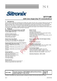
7 Mechanical Drawing<br />
X+<br />
Y+<br />
Y-<br />
PIN 1<br />
X-<br />
TP PIN<br />
7.60<br />
Formike Electronic Co.,Ltd.<br />
<strong>KWH102KQ03</strong>-F01<br />
-27-
Formike Electronic Co.,Ltd.<br />
Issued Date : 2007-03-05<br />
MODEL NO :<strong>KWH102KQ03</strong>-<strong>F02</strong><br />
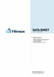
8 Package Drawing<br />
8.1 Packaging Material Table<br />
No.<br />
1<br />
Item<br />
LCM<br />
module<br />
2 Partition<br />
3<br />
4<br />
5<br />
Partition<br />
Paper<br />
Corrugated<br />
Bar<br />
Dust-Proof<br />
Bag<br />
Model<br />
(Material)<br />
Dimensions(mm)<br />
Unit<br />
Weight<br />
(kg)<br />
KWH102QC03 235X145.8X6.1 0.335 25<br />
BC Corrugated<br />
paper<br />
B Corrugated<br />
paper<br />
B Corrugated<br />
paper<br />
512X349X226 1.35 1<br />
510X350X7 0.148 2<br />
512X370X7 0.11 2<br />
PE 900X700X0.05 0.01 1<br />
6 A/S Bag PE 280X200X0.05 0.001 25<br />
7 Carton<br />
Corrugated<br />
paper<br />
8 Total weight 12.576 Kg ± 5%<br />
530X355X255 2.3 1<br />
Quantity<br />
Remark<br />
10 9 ~<br />
10 11 Ω/sq<br />
8.2 Packaging Quantity<br />
Total LCM quantity in Carton: no. of Partition 1 Rows x quantity per Row 25 = 25<br />
-28-