XLR130 â XLR170 - Copyright Arctica Oy
XLR130 â XLR170 - Copyright Arctica Oy
XLR130 â XLR170 - Copyright Arctica Oy

You also want an ePaper? Increase the reach of your titles
YUMPU automatically turns print PDFs into web optimized ePapers that Google loves.
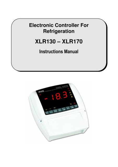
Electronic Controller For<br />
Refrigeration<br />
<strong>XLR130</strong> – <strong>XLR170</strong><br />
Instructions Manual
dIXEL<br />
dIXEL Installing and Operating Instructions rel.2.0<br />
.0 - cod. 1592017000<br />
COOL<br />
OOLMATE<br />
<strong>XLR130</strong>C – <strong>XLR170</strong>C<br />
INDEX<br />
To translate this manual in you language you can start from the manual of XW570L code: “1592009130 XW570L GB.doc” and translate the part in<br />
RED colour.<br />
1. GENERAL WARNING 3<br />
2. GENERAL DESCRIPTION 3<br />
3. CONTROLLING LOADS 3<br />
4. KEYBOARD 5<br />
5. REAL TIME CLOCK FUNCTION – ONLY FOR INSTRUMENTS WITH RTC 8<br />
6. PARAMETER LIST 8<br />
7. DIGITAL INPUTS 11<br />
8. INSTALLATION AND MOUNTING 12<br />
9. DIMENSIONS 14<br />
10. ELECTRICAL CONNECTIONS 14<br />
11. TTL SERIAL LINE 14<br />
12. HOW TO USE THE HOT KEY 14<br />
13. ALARM SIGNALS 15<br />
14. TECHNICAL DATA 15<br />
15. CONNECTIONS 16<br />
16. DEFAULT SETTING VALUES 17<br />
1592017000 XLR 130-170 GB r2.0 08.09.2006.doc XL130 - <strong>XLR170</strong> 2/19
dIXEL<br />
dIXEL Installing and Operating Instructions rel.2.0<br />
.0 - cod. 1592017000<br />
1. GENERAL WARNING<br />
1.1 PLEASE READ BEFORE USING THIS MANUAL<br />
• This manual is part of the product and should be kept near the instrument for easy and quick reference.<br />
• The instrument shall not be used for purposes different from those described hereunder. It cannot be used as a safety device.<br />
• Check the application limits before proceeding.<br />
1.2 SAFETY PRECAUTIONS<br />
• Check the supply voltage is correct before connecting the instrument.<br />
• Do not expose to water or moisture: use the controller only within the operating limits avoiding sudden temperature changes with high<br />
atmospheric humidity to prevent formation of condensation<br />
• Warning: disconnect all electrical connections before any kind of maintenance.<br />
• Fit the probe where it is not accessible by the End User. The instrument must not be opened.<br />
• In case of failure or faulty operation send the instrument back to the distributor or to “Dixell S.p.A.” (see address) with a detailed description of<br />
the fault.<br />
• Consider the maximum current which can be applied to each relay (see Technical Data).<br />
• Ensure that the wires for probes, loads and the power supply are separated and far enough from each other, without crossing or intertwining.<br />
• In case of applications in industrial environments, the use of mains filters (our mod. FT1) in parallel with inductive loads could be useful.<br />
2. GENERAL DESCRIPTION<br />
Models <strong>XLR130</strong> and <strong>XLR170</strong>, 210x230mm format, are microprocessor based controllers suitable for applications on medium or low temperature<br />
refrigerating units. They are provided with four (<strong>XLR130</strong>) or six (<strong>XLR170</strong>) relay outputs to control compressor, defrost - which can be either electrical<br />
or hot gas (<strong>XLR170</strong>) - the evaporator fans (<strong>XLR170</strong>), the lights, the alarm and an auxiliary output. They are also provided with three NTC or PTC<br />
probe inputs, one for temperature control, one to control the defrost end temperature of the evaporator and the third, optional, for the display. There<br />
are two digital inputs (free contact) for the door switch and configurable by parameter.<br />
The standard TTL output allows the user to connect, by means of a TTL/RS485 external module, a ModBUS-RTU compatible monitoring system and<br />
to programme the parameter list with the “Hot Key”.<br />
Each model in the XLR100 can be provided with a Real Time Clock which allows programming of up to eight daily defrost cycles, divided into<br />
holidays and workdays. A “Day and Night” function with two different set points is fitted for energy saving.<br />
3. CONTROLLING LOADS<br />
3.1 THE COMPRESSOR<br />
The regulation is performed according to the temperature measured by the thermostat probe with a positive differential from the set point: if the<br />
temperature increases and reaches set point plus differential the compressor is started and then turned off when the temperature reaches the set<br />
point value again.<br />
In case of fault in the thermostat probe the start and stop of the compressor are timed through parameters “COn” and “COF”.<br />
3.2 FAST FREEZING<br />
When defrost is not in progress, it can be activated the keypad by holding the o key pressed for about 3 seconds. The compressor operates in<br />
continuous mode for the time set through the “CCt” parameter. The cycle can be terminated before the end of the set time using the same activation<br />
key, o for about 3 seconds.<br />
3.3 DEFROST<br />
3.3.1 <strong>XLR130</strong> – TIMED DEFROST<br />
The defrost interval is controlled by means of parameter “EdF”:<br />
- with EdF=in the defrost is made every “IdF” time,<br />
- with EdF=Sd the interval “IdF” is calculate through Smart Defrost algorithm (the counter is increased only when the compressor is ON).<br />
- with real time clock present EdF can be set to “rtc”, In this case, the defrost is made in real time depending on the hours set in the parameters<br />
Ld1..Ld8 on workdays and in Sd1…Sd8 in holidays;<br />
Defrost is performed through a simple stop of the compressor. Parameter “IdF” controls the interval between defrost cycles, while its length is<br />
controlled by parameter “MdF”.<br />
3.3.2 <strong>XLR170</strong> – HEATER OR HOT GAS DEFROST<br />
Three defrost modes are available through the “tdF” parameter: defrost with electrical heater (tdF=rE),<br />
defrost(tdF=rt).<br />
The defrost interval is controlled by means of parameter “EdF”:<br />
hot gas (tdF=in), or thermostatic<br />
1592017000 XLR 130-170 GB r2.0 08.09.2006.doc XL130 - <strong>XLR170</strong> 3/19
dIXEL<br />
dIXEL Installing and Operating Instructions rel.2.0<br />
.0 - cod. 1592017000<br />
- with EdF=in the defrost is made every “IdF” time,<br />
- with EdF=Sd the interval “IdF” is calculate through Smart Defrost algorithm (the counter is increased only when the compressor is ON).<br />
- with real time clock present EdF can be set to “rtc”. In this case, the defrost is made in real time depending on the hours set in the parameters<br />
Ld1..Ld8 on workdays and in Sd1…Sd8 in holidays;<br />
At the end of defrost the drip time is controlled through the “Fdt” parameter.<br />
3.4 CONTROL OF EVAPORATOR FANS (<strong>XLR170</strong> OR <strong>XLR130</strong> WITH OA1=FAN)<br />
The fan control mode is selected by means of the “FnC” parameter:<br />
C-n fans will switch ON and OFF with the compressor and not run during defrost;<br />
C-y fans will switch ON and OFF with the compressor, also during defrost<br />
After defrost, there is a timed fan delay allowing for drip time, set by means of the “Fnd” parameter.<br />
O-n fans will run continuously and not run during defrost;<br />
O-y fans will run continuously also during defrost<br />
An additional parameter “FSt” provides the setting of temperature, detected by the evaporator probe, above which the fans are always OFF. This can<br />
be used to make sure circulation of air only if his temperature is lower than set in “FSt”.<br />
3.5 AUXILIARY OUTPUT CONFIGURATION - TERM. 15-16, PAR. OA1<br />
The functioning of the auxiliary relay (terminals. 15-16) can be set by the oA1 parameter, according to the kind of application. In the following<br />
paragraph the possible setting:<br />
3.5.1 <strong>XLR130</strong>: forced air application, normal temperature -oA1= Fan<br />
Parameters involved:<br />
- FnC Fan operating mode; - Fnd Fan delay after a defrost<br />
- FSt Fan stop temperature; - FAP Probe for fan management<br />
With this setting the auxiliary relay works as fan relay. See par. 3.4 “Control of evaporator fans”.<br />
NOTE: if FAP = nP (no probe), the relay will be activated according to the setting of FnC parameter independently from the temperature of<br />
evaporator.<br />
3.5.2 Auxiliary relay - oA1= AUS<br />
With oA1=AUS, two kinds of working are available.<br />
A. The AUX relay is activated only by keyboard<br />
Set oA1 =AUS and ArP= nP (no probe for auxiliary output).<br />
In this case the relay 15-16 can be activated only by pushing the AUX button of the keyboard.<br />
B. Auxiliary thermostat (I.E.. anti condensing heater) with the possibility of switching it on and off also by keyboard<br />
Parameters involved:<br />
- ACH Kind of regulation for the auxiliary relay: heating /cooling;<br />
- SAA Set point for auxiliary relay<br />
- ArP Probe for auxiliary relay<br />
By means of these 3 parameters the functioning of the auxiliary relay can be set.. The differential is given by the Hy parameter.<br />
The auxiliary relay can be switched on also by the AUX button. In this case it remains on till it’s manually switched off.<br />
The defrost doesn’t affect the status of auxiliary relay.<br />
3.5.3 on/off relay - oA1 = onF<br />
In this case the relay is activated when the controller is turned on and de-activated when the controller is turned off..<br />
3.5.4 <strong>XLR170</strong>: Second defrost relay for applications with 2 evaporators – oA1 = dF2<br />
Parameters involved:<br />
- dtS end defrost temperature for second defrost relay;<br />
- MdS maximum defrost duration for second defrost relay;<br />
- dSP probe selection for second defrost<br />
With 2 evaporators the regulation restarts when both the defrosts are finished.<br />
3.5.5 Second compressor – oA1 = cP2<br />
In this case the controller can manage 2 compressors or a 2 step compressor.<br />
Functioning: the 2 nd compressor is activated after the fist compressor with a delay set in the Ac1 parameter (seconds). Both compressor are<br />
turned off at the same time.<br />
1592017000 XLR 130-170 GB r2.0 08.09.2006.doc XL130 - <strong>XLR170</strong> 4/19
dIXEL<br />
dIXEL Installing and Operating Instructions rel.2.0<br />
.0 - cod. 1592017000<br />
If cco=AL compressors are switched on by turn.<br />
Parameters involved:<br />
- cco Compressor activation: type of sequence: by turn or in sequence;<br />
- Ac1 Second compressor activation delay (seconds);<br />
4. KEYBOARD<br />
Panic LED<br />
To display and modify target set point; in programming mode it selects a parameter or confirms an operation.<br />
By holding it pressed for 3s when max or min temperature is displayed, it will be erased.<br />
Only for models with RTC: by pressing it when the current time is displayed, it allows the User to re-set the current time and three<br />
holidays.<br />
To see the max. stored temperature; in programming mode it browses the parameter codes or increases the displayed value. By<br />
holding it pressed for 3s the fast freezing cycle is started.<br />
To see the min stored temperature; in programming mode it browses the parameter codes or decreases the displayed value.<br />
Only for models with RTC: by holding it pressed for 3s the current time is displayed and it permits the User to enter Energy saving,<br />
Defrost and Clock parameter menu.<br />
By holding it pressed for 3s the defrost is started.<br />
Only for models with RTC by pressing it when the current time is displayed, it allows the User to set defrost times.<br />
KEY COMBINATIONS<br />
Switch ON and OFF the cold room light.<br />
To start and stop Energy Saving function.<br />
Only for models with RTC: by holding it pressed for 6s, the holiday function is started or stopped.<br />
By pressing it when the current time is displayed, it allows the User to set Energy Saving times.<br />
If oA1 = AUS, it switches ON and OFF the auxiliary output.<br />
To switch ON and OFF the instrument.<br />
+<br />
To lock and unlock the keyboard.<br />
+<br />
To enter the programming mode.<br />
+<br />
To exit the programming mode.<br />
1592017000 XLR 130-170 GB r2.0 08.09.2006.doc XL130 - <strong>XLR170</strong> 5/19
dIXEL<br />
dIXEL Installing and Operating Instructions rel.2.0<br />
.0 - cod. 1592017000<br />
4.1 USE OF LEDS<br />
Each LED function is described in the following table.<br />
LED MODE Function<br />
°C ON Celsius degrees display<br />
°C FLASHING Programming phase<br />
°F ON Fahrenheit degrees display<br />
ON The compressor is running<br />
FLASHING - Programming Phase (flashing with LED )<br />
- Anti-short cycle delay enabled<br />
ON The fan is running<br />
FLASHING<br />
ON<br />
FLASHING<br />
ON<br />
ON<br />
AUX ON<br />
ON<br />
ON<br />
ON<br />
Programming Phase (flashing with LED )<br />
The defrost is enabled<br />
Drip time in progress<br />
The Fast Freezing cycle is enabled<br />
- ALARM signal<br />
- In “Pr2” indicates that the parameter is also present in “Pr1”<br />
Auxiliary output (15-16) on (oA1=AUS).<br />
Energy saving on<br />
Light on<br />
The instrument is off<br />
4.2 4.2 HOW TO SEE THE MIN TEMPERATURE<br />
1. Press and release the n key.<br />
2. The “Lo” message will be displayed followed by the minimum temperature recorded.<br />
3. By pressing the n key or waiting for 5s the normal display will be restored.<br />
4.3 4.3 HOW TO SEE THE MAX TEMPERATURE<br />
1. Press and release the o key.<br />
2. The “Hi” message will be displayed followed by the maximum temperature recorded.<br />
3. By pressing the o key or waiting for 5s the normal display will be restored.<br />
4.4 4.4 HOW TO RESET THE MAX AND MIN TEMPERATURE RECORDED<br />
To reset the stored temperature, when max or min temperature is displayed :<br />
1. Press SET key until “rST” label starts blinking.<br />
N.B. After the installation RESET the temperature stored .<br />
4.5 HOW TO SEE AND MODIFY THE SET POINT<br />
1. Push and immediately release the SET key: the display will show the Set point value;<br />
2. The “°C” LED starts blinking;<br />
3. To change the Set value push the o or n arrows within 10s.<br />
4. To memorise the new set point value push the SET key again or wait 10s.<br />
4.6 TO START A MANUAL DEFROST<br />
Push the DEF key for more than 2 seconds and a manual defrost will start.<br />
4.7 TO ENTER IN PARAMETERS LIST “PR1”<br />
To enter the parameter list “Pr1” (user accessible parameters) operate as follows:<br />
1. Enter the Programming mode by pressing the Set and DOWN key for few seconds (“°C” LED starts blinking).<br />
2. The instrument will show the first parameter present in “Pr1”<br />
+<br />
1592017000 XLR 130-170 GB r2.0 08.09.2006.doc XL130 - <strong>XLR170</strong> 6/19
dIXEL<br />
dIXEL Installing and Operating Instructions rel.2.0<br />
.0 - cod. 1592017000<br />
4.8 TO ENTER IN PARAMETERS LIST “PR2”<br />
To access parameters in “Pr2”:<br />
1. Enter the “Pr1” level.<br />
2. Select “Pr2” parameter and press the “SET” key.<br />
3. The “PAS” flashing message is displayed, shortly followed by “0 - -” with a flashing zero.<br />
4. Use o or n to input the security code in the flashing digit; confirm the figure by pressing “SET”.<br />
The security code is “321“.<br />
5. If the security code is correct the access to “Pr2” is enabled by pressing “SET” on the last digit.<br />
Another possibility is the following: after switching ON the instrument the user can push Set and DOWN keys within 30 seconds.<br />
NOTE: each parameter in “Pr2” can be removed or put into “Pr1” (user level) by pressing “SET” + n. When a parameter is present in “Pr1” “decimal<br />
point “ is on.<br />
4.9 HOW TO CHANGE THE PARAMETER VALUE<br />
1. Enter the Programming mode.<br />
2. Select the required parameter with o or n.<br />
3. Press the “SET” key to display its value (“°C” LED starts blinking).<br />
4. Use o or n to change its value.<br />
5. Press “SET” to store the new value and move to the following parameter.<br />
To exit: Press SET + UP or wait 15s without pressing a key.<br />
NOTE: the new programming is stored even when the procedure is exited by waiting the time-out.<br />
4.10 HOW TO LOCK THE KEYBOARD<br />
1. Keep the o and n keys pressed together for more than 3 s the o and n keys.<br />
2. The “POF” message will be displayed and the keyboard is locked. At this point it is only possible the viewing of the set point or the<br />
MAX o Min temperature stored and to switch ON and OFF the light and the auxiliary output.<br />
+<br />
TO UNLOCK THE KEYBOARD<br />
Keep the o and n keys pressed together for more than 3s.<br />
4.11 ON/OFF FUNCTION<br />
By pushing the ON/OFF key, the instrument shows “OFF” for 5 sec. and the ON/OFF LED is switched ON.<br />
During the OFF status, all the relays are switched OFF and the regulations are stopped; if a monitoring system is connected, it does not<br />
record the instrument data and alarms.<br />
N.B. During the OFF status the Light and AUX buttons are active.<br />
4.12 TO SEE THE PROBE VALUES<br />
1. Enter in “Pr1” level.<br />
2. Select “dP1” parameter for probe 1, “dP2” parameter for probe 2, “dP3” parameter for probe 3, with o or n.<br />
3. Press the “SET” key to see the value of the selected probe.<br />
4. Press “SET” to move to the following parameter.<br />
1592017000 XLR 130-170 GB r2.0 08.09.2006.doc XL130 - <strong>XLR170</strong> 7/19
dIXEL<br />
dIXEL Installing and Operating Instructions rel.2.0<br />
.0 - cod. 1592017000<br />
5. REAL TIME CLOCK FUNCTION – ONLY FOR INSTRUMENTS WITH RTC<br />
5.1 TO SEE THE CURRENT TIME AND DAY<br />
1. Push the n key for more than 3 seconds<br />
2.<br />
e<br />
LED switches ON and the following messages are displayed:<br />
Hur (hour); Min (Minute); dAY (day)<br />
3. To exit push n key or wait 5 seconds<br />
5.2 TO SET THE TIME AND THE WEEKLY HOLIDAYS<br />
followe<br />
d by<br />
1. Push the n key for more than 3 seconds<br />
2.<br />
e<br />
LED switches ON and the current time is displayed.<br />
3. By pushing the SET key, the e<br />
LED will start flashing and setting the current hour, minutes, day and the weekly holidays (up<br />
to 3) will be possible.<br />
4. To exit, press SET + UP or wait 15s without pressing any key.<br />
5.3 TO SET THE DEFROST TIMES<br />
followe<br />
d by<br />
1. Push the n key for more than 3 seconds<br />
2.<br />
e<br />
LED switches ON and the current time is displayed.<br />
3. By pushing DEF key, the DEF led will start flashing and setting defrost time will be possible.<br />
4. To exit, press SET + UP or wait 15s without pressing any key.<br />
5.4 TO SET THE ENERGY SAVING TIMES<br />
followe<br />
d by<br />
1. Push the n key for more than 3 seconds<br />
2.<br />
e<br />
LED switches ON and the current time is displayed.<br />
3. By pushing the ES key, the ES led will start flashing and setting Energy Saving time will be possible.<br />
4. To exit, press SET + UP or wait 15s without pressing any key.<br />
5.5 TO START HOLIDAY FUNCTION BY USING THE KEYBOARD<br />
1. Push the ES key for more than 6 seconds until the label “Hd” is shown.<br />
2.<br />
e<br />
LED will start to blink slower than during time programming and the regulators will follow holiday times.<br />
3. Push the ES key for more than 6 seconds to start normal functioning again.<br />
6. PARAMETER LIST<br />
REGULATION<br />
Hy Differential: (0,1÷25,5°C; 1÷45°F): Intervention differential for set point, always positive. Compressor Cut IN is Set Point Plus Differential (Hy).<br />
Compressor Cut OUT is when the temperature reaches the set point.<br />
LS Minimum set point limit: (-50,0°C÷SET; -58°F÷SET) Sets the minimum acceptable value for the set point.<br />
US Maximum set point limit: (SET÷110°C; SET÷230°F) Set the maximum acceptable value for set point.<br />
odS Outputs activation delay at start up: (0÷255 min) This function is enabled at the initial start up of the instrument and inhibits any output<br />
activation for the period of time set in the parameter. (AUX and Light can work)<br />
cco Compressors: kind of activation. Used only if oA1 =cP2: SE = sequential activation; AL = by turn activation<br />
AC Anti-short cycle delay: (0÷30 min) interval between the compressor stop and the following restart.<br />
Ac1 2 nd compressor delay at start up (0÷255s) Time interval between the switching on of the first compressor and the second one. (0÷225s).<br />
CCt Thermostat override: (0min ÷23h 50min) allows to set the length of the continuous cycle. Can be used, for instance, when the room is filled<br />
with new products.<br />
Con Compressor ON time with faulty probe: (0÷255 min) time during which the compressor is active in case of faulty thermostat probe. With<br />
COn=0 compressor is always OFF.<br />
1592017000 XLR 130-170 GB r2.0 08.09.2006.doc XL130 - <strong>XLR170</strong> 8/19
dIXEL<br />
dIXEL Installing and Operating Instructions rel.2.0<br />
.0 - cod. 1592017000<br />
COF Compressor OFF time with faulty probe: (0÷255 min) time during which the compressor is off in case of faulty thermostat probe. With<br />
COF=0 compressor is always active.<br />
CH Type of action - Only for <strong>XLR130</strong>: CL = cooling; Ht = heating..<br />
DISPLAY<br />
CF Temperature measurement unit: °C = Celsius; °F = Fahrenheit . When the measurement unit is changed the SET point and the values of the<br />
regulation parameters have to be modified<br />
rES Resolution (for °C): (in = 1°C; de = 0,1°C) allows decimal point display. dE = 0,1°C; in = 1 °C<br />
Lod Local display : select which probe is displayed by the instrument: P1 = Thermostat probe; P2 = Evaporator probe; P3 = auxiliary probe<br />
1r2 = difference between P1 and P2 (P1-P2)<br />
DEFROST<br />
tdF Defrost type Only for <strong>XLR170</strong>: rE = electrical heater (Compressor OFF); rT = thermostat defrost. During the defrost time “MdF”, the heater<br />
switches On and OFF depending on the evaporator temperature and “dtE” value; in = hot gas (Compressor and defrost relays ON)<br />
EdF Defrost mode:<br />
rtc = Real Time Clock mode. Defrost time follows Ld1÷Ld8 parameters on workdays and Sd1÷Sd8 on holidays. Available only if the ’RTC<br />
option is present<br />
in = interval mode. The defrost starts when the time “Idf” is expired.<br />
Sd = Smartfrost mode. The time IdF (interval between defrosts) is increased only when the compressor is running (even non consecutively)<br />
and only if the evaporator temperature is less than the value in "SdF” (set point for SMARTFROST).<br />
SdF Set point for SMARTFROST: (-30÷30 °C/ -22÷86 °F) evaporator temperature which allows the IdF counting (interval between defrosts) in<br />
SMARTFROST mode.<br />
dtE Defrost termination temperature Only for <strong>XLR170</strong>: (-50,0÷110,0°C; -58÷230°F) (Enabled only when the evaporator probe is present) sets<br />
the temperature measured by the evaporator probe which causes the end of defrost.<br />
dtS Defrost termination temperature 2 nd evaporator – Only for <strong>XLR170</strong> if oA1=dF2 : (-50,0÷110,0°C; -58÷230°F) sets the temperature<br />
measured by the 2 nd evaporator probe which causes the end of defrost.<br />
IdF Interval between defrosts: (1÷120h) Determines the time interval between the beginning of two defrost cycles.<br />
MdF (Maximum) duration of defrost: (0÷255 min) When P2P = n, no evaporator probe, it sets the defrost duration, when P2P = y, defrost end<br />
based on temperature, it sets the maximum length for defrost.<br />
MdS (Maximum) duration of defrost for 2 nd evaporator – Only for <strong>XLR170</strong> if oA1=dF2: (0÷255 min) It sets the maximum duration of the defrost<br />
for 2 nd evaporator.<br />
dFd Display during defrost: rt = real temperature; it = temperature at the defrost start; Set = set point; dEF = “dEF” label; dEG = “dEG” label;<br />
dAd Defrost display time out: (0÷255 min) Sets the maximum time between the end of defrost and the restarting of the real room temperature<br />
display.<br />
dSd Start defrost delay - Only for <strong>XLR170</strong>: ( 0÷99min) This is useful when different defrost start times are necessary to avoid overloading the<br />
plant.<br />
Fdt Drain down time: (0÷60 min.) time interval between reaching defrost termination temperature and the restoring of the control’s normal<br />
operation. This time allows the evaporator to eliminate water drops that might have formed due to defrost.<br />
dPO First defrost after start-up:<br />
y = Immediately; n = after the IdF time<br />
dAF Defrost delay after fast freezing: (0min÷23h 50min) after a Fast Freezing cycle, the first defrost will be delayed for this time.<br />
dFP End defrost probe for first evaporator selection – Only for <strong>XLR170</strong>: nP = no probe, defrost by time. Duration set by MdF parameter; P1 =<br />
Probe 1 (thermostat probe); P2 = Probe 2 (evaporator probe); P3 = Probe 3 (display probe).<br />
dSP End defrost probe for second evaporator selection – Only for <strong>XLR170</strong>: nP = no probe, defrost by time. Duration set by MdS parameter; P1<br />
= Probe 1 (thermostat probe); P2 = Probe 2 (evaporator probe); P3 = Probe 3 (display probe).<br />
FANS<br />
FnC Fan operating mode: C-n = running with the compressor, OFF during the defrost;<br />
C-y = running with the compressor, ON during the defrost;<br />
O-n = continuous mode, OFF during the defrost;<br />
O-y = continuous mode, ON during the defrost;<br />
Fnd Fan delay after defrost: (0÷255 min) The time interval between the defrost end and evaporator fans start.<br />
FSt Fan stop temperature: (-50÷110°C; -58÷230°F) setting of temperature, detected by evaporator probe, above which the fan is always OFF.<br />
dSP Fan probe selection: nP = no probe, fans act according to the Fnc parameter, without temperature control set in FSt parameter; P1 = Probe 1<br />
(Thermostat probe); P2 = Probe 2 (evaporator probe); P3 = Probe 3 (display probe).<br />
ALARMS<br />
ALC Temperature alarm configuration: rE = High and Low alarms related to Set Point;<br />
Ab = High and low alarms related to the absolute temperature.<br />
ALU High temperature alarm setting: ( ALC= rE, 0 ÷ 50°C or 90°F; ALC= Ab, ALL ÷ 110°C or 230°F)<br />
when this temperature is reached and after the ALd delay time the HA alarm is enabled.<br />
ALL Low temperature alarm setting: ( ALC = rE , 0 ÷ 50 °C or 90°F; ALC = Ab , - 50°C or -58°F ÷ ALU)<br />
when this temperature is reached and after the ALd delay time, the LA alarm is enabled,.<br />
AFH Temperature alarm and fan differential: (0,1÷25,5°C; 1÷45°F) Intervention differential for temperature alarm set point and fan regulation set<br />
point, always positive.<br />
1592017000 XLR 130-170 GB r2.0 08.09.2006.doc XL130 - <strong>XLR170</strong> 9/19
dIXEL<br />
dIXEL Installing and Operating Instructions rel.2.0<br />
.0 - cod. 1592017000<br />
ALd Temperature alarm delay: (0÷255 min) time interval between the detection of an alarm condition and the corresponding alarm signalling.<br />
dAO Delay of temperature alarm at start-up: (0min÷23h 50min) time interval between the detection of the temperature alarm condition after the<br />
instrument power on and the alarm signalling.<br />
EdA Alarm delay at the end of defrost: (0÷255 min) Time interval between the detection of the temperature alarm condition at the end of defrost<br />
and the alarm signalling.<br />
dot Delay of temperature alarm after closing the door : (0÷255 min) Time delay to signal the temperature alarm condition after closing the door.<br />
doA Open door alarm delay:(0÷254min,nu) delay between the detection of the open door condition and its alarm signalling: the flashing message<br />
“dA” is displayed. If doA=nu the door alarm will be not signalled.<br />
rrd Output restart after door open alarm doA: no = outputs unchanged after doA alarm; yES = outputs restart after doA alarm;<br />
tbA Buzzer and alarm relay silencing: by pushing one of the keypad buttons.<br />
n= Only the Buzzer is silenced; y= Buzzer and relay are silenced.<br />
nPS Pressure switch number: (0 ÷15) Number of activation of the pressure switch, during the “did” interval, before signalling the alarm event (I2F=<br />
PAL).<br />
PROBE INPUTS<br />
Ot Thermostat probe calibration: (-12.0÷12.0°C/ -21÷21°F) allows to adjust possible offset of the thermostat probe.<br />
OE Evaporator probe calibration – Only for <strong>XLR170</strong>: (-12.0÷12.0°C/ -21÷21°F) allows to adjust possible offsets of the evaporator probe.<br />
O3 Auxiliary probe calibration: (-12.0÷12.0°C/ -21÷21°F) allows to adjust possible offsets of the evaporator probe.<br />
P2P Evaporator probe presence - Only for <strong>XLR170</strong>:<br />
n= not present: the defrost stops only by time; y= present: the defrost stops by temperature and time.<br />
P3P Auxiliary probe presence (display): n= not present; y= present.<br />
Pbr Thermostat probe selection P1 = Probe 1 (Thermostat probe); P2 = Probe 2 (evaporator probe); P3 = Probe 3 (display probe); 1r2 = P1-P2.<br />
HES Temperature increase during the Energy Saving cycle : (-30÷30°C / -54÷54°F) sets the increasing value of the set point during the Energy<br />
Saving cycle.<br />
DIGITAL INPUTS<br />
odc Compressor and fan status when open door:<br />
no = normal; Fan = Fan OFF; CPr = Compressor OFF; F_C = Compressor and fan OFF.<br />
I1P Door switch input polarity: CL : the digital input is activated by closing the contact; OP : the digital input is activated by opening the contact.<br />
I2P Configurable digital input polarity: CL : the digital input is activated by closing the contact;<br />
OP : the digital input is activated by opening the contact<br />
I2F Digital input operating mode: configure the digital input function: EAL = generic alarm; bAL = serious alarm mode; PAL = Pressure switch;<br />
dFr = Start defrost; AUS = Relay AUX actuation; Es = Energy Saving; onF = remote On/OFF; HdF = Holiday function.<br />
did Time interval/delay for digital input alarm:(0÷255 min.) Time interval to calculate the number of the pressure switch activation when<br />
I2F=PAL. If I2F=EAL or bAL (external alarms), “did” parameter defines the time delay between the detection and the successive signalling of<br />
the alarm.<br />
AUXILIARY RELAY CONFIGURATION<br />
oA1 Auxiliary relay configuration (terminals 15-16): dEF = Not set it; ALr = alarm; FAn = fans; Lig =light; AUS = auxiliary; onF = on/off; dF2 =<br />
second defrost (only for <strong>XLR170</strong>), cP2 = second compressor (only for <strong>XLR170</strong>).<br />
AUXILIARY THERMOSTAT CONFIGURATION (terms. 15-16) – OA1 = AUS<br />
ACH Kind of regulation for auxiliary relay: Ht = heating; CL = cooling<br />
SAA Set Point for auxiliary relay: (-50,0÷110,0°C; -58÷230°F) it defines the room temperature setpoint to switch auxiliary relay.<br />
ArP Probe selection for auxiliary: nP = no probe, the auxiliary relay is switched only by button; P1 = Probe 1 (Thermostat probe); P2 = Probe 2<br />
(evaporator probe); P3 = Probe 3 (display probe).<br />
AoP Alarm relay polarity (terms. 29-30-31): oP = 29-30 terminals open with alarm; cL = 29-30 terminals close with alarm<br />
TO SET CURRENT TIME AND WEEKLY HOLIDAYS ( 3SEC followed by ) – Only for models with RTC<br />
Hur Current hour (0 ÷ 23 h)<br />
Min Current minute (0 ÷ 59min)<br />
dAY Current day (Sun ÷ SAt)<br />
Hd1 First weekly holiday (Sun ÷ nu) Set the first day of the week which follows the holiday times.<br />
Hd2 Second weekly holiday (Sun ÷ nu) Set the second day of the week which follows the holiday times.<br />
Hd3 Third weekly holiday (Sun ÷ nu) Set the third day of the week which follows the holiday times.<br />
N.B.<br />
Hd1,Hd2,Hd3 can be set also as “nu” value (Not Used).<br />
TO SET ENERGY SAVING TIMES (3SEC. afterward )<br />
ILE Energy Saving cycle start during workdays: (0 ÷ 23h 50 min.) During the Energy Saving cycle the set point is increased by the value in<br />
HES so that the operation set point is SET + HES.<br />
dLE Energy Saving cycle length during workdays: (0 ÷ 24h 00 min.) Sets the duration of the Energy Saving cycle on workdays.<br />
1592017000 XLR 130-170 GB r2.0 08.09.2006.doc XL130 - <strong>XLR170</strong> 10/19
dIXEL<br />
dIXEL Installing and Operating Instructions rel.2.0<br />
.0 - cod. 1592017000<br />
ISE Energy Saving cycle start on holidays. (0 ÷ 23h 50 min.)<br />
dSE Energy Saving cycle length on holidays (0 ÷ 24h 00 min.)<br />
HES Temperature increase during the Energy Saving cycle (-30÷30°C / -54÷54°F) sets the increasing value of the set point during the Energy<br />
Saving cycle.<br />
TO SET DEFROST TIMES (3SEC. afterward )<br />
Ld1÷Ld8 Workday defrost start (0 ÷ 23h 50 min.) These parameters set the beginning of the eight programmable defrost cycles during workdays.<br />
Ex. When Ld2 = 12.4 the second defrost starts at 12.40 during workdays.<br />
Sd1÷Sd8 Holiday defrost start (0 ÷ 23h 50 min.) These parameters set the beginning of the eight programmable defrost cycles on holidays. Ex.<br />
When Sd2 = 3.4 the second defrost starts at 3.40 on holidays.<br />
N.B. :To disable a defrost cycle set it to “nu”(not used). Ex. If Ld6=nu ; the sixth defrost cycle is disabled<br />
OTHER<br />
Adr RS485 serial address (1÷247): Identifies the instrument address when connected to a ModBUS compatible monitoring system.<br />
PbC Probe selection: (Ptc=PTC probe; ntc=NTC probe). It allows to select the kind of probe.<br />
Rel Release software: (read only) Software version of the microprocessor.<br />
Ptb Parameter table: (read only) it shows the original code of the dIXEL parameter map.<br />
dP1 Probe 1 temperature (thermostat): it displays the temperature detected by the thermostat probe.<br />
dP2 Probe 2 temperature (evaporator): it displays the temperature detected by the evaporator probe.<br />
dP3 Probe 3 temperature (display): it displays the temperature detected by the display probe.<br />
Pr2 Access to the protected parameter list (read only).<br />
7. DIGITAL INPUTS<br />
The Wing series can support up to 2 free contact digital inputs. One is always configured as door switch, the second is programmable in seven<br />
different configurations by the “I2F” parameter.<br />
7.1 DOOR SWITCH INPUT<br />
It signals the door status and the corresponding relay output status through the “odc” parameter:<br />
no = normal (any change);<br />
Fan = Fan OFF;<br />
CPr = Compressor OFF;<br />
F_C = Compressor and fan OFF.<br />
Since the door is opened, after the delay time set through parameter “dOA”, the alarm output is enabled and the display shows the message “dA”.<br />
The alarm stops as soon as the external digital input is disabled again. During this time and then for the delay “dot” after closing the door, the high<br />
and low temperature alarms are disabled.<br />
7.2 CONFIGURABLE INPUT - GENERIC ALARM (EAL)<br />
As soon as the digital input is activated the unit will wait for “did” time delay before signalling the “EAL” alarm message. The outputs status don’t<br />
change. The alarm stops just after the digital input is de-activated.<br />
7.3 CONFIGURABLE INPUT - PANIC ALARM (i2F = PAn)<br />
As soon as the digital input is activated the unit displays the “PAn” alarm message, the alarm buzzer, relay and panic LED are activated. The other<br />
outputs status don’t change. The alarm stops just after the digital input is de-activated.<br />
7.4 CONFIGURABLE INPUT - SERIOUS ALARM MODE (BAL)<br />
When the digital input is activated, the unit will wait for “did” delay before signalling the “BAL” alarm message. The relay outputs are switched OFF.<br />
The alarm will stop as soon as the digital input is de-activated.<br />
7.5 CONFIGURABLE INPUT - PRESSURE SWITCH (PAL)<br />
If during the interval time set by “did” parameter, the pressure switch has reached the number of activation of the “nPS” parameter, the “PAL”<br />
pressure alarm message will be displayed. The compressor and the regulation are stopped. When the digital input is ON the compressor is always<br />
OFF.<br />
7.6 CONFIGURABLE INPUT - START DEFROST (DFR)<br />
It executes a defrost if there are the right conditions. After the defrost is finished, the normal regulation will restart only if the digital input is disabled<br />
otherwise the instrument will wait until the “Mdf” safety time is expired.<br />
7.7 CONFIGURABLE INPUT - RELAY AUX ACTUATION (AUS)<br />
This function allows to turn ON and OFF the auxiliary relay by using the digital input as external switch.<br />
1592017000 XLR 130-170 GB r2.0 08.09.2006.doc XL130 - <strong>XLR170</strong> 11/19
dIXEL<br />
dIXEL Installing and Operating Instructions rel.2.0<br />
.0 - cod. 1592017000<br />
7.8 CONFIGURABLE INPUT - ENERGY SAVING (ES)<br />
The Energy Saving function allows to change the set point value as the result of the SET+ HES (parameter) sum. This function is enabled until the<br />
digital input is activated.<br />
7.9 CONFIGURABLE INPUT - REMOTE ON/OFF (ONF)<br />
This function allows to switch ON and OFF the instrument.<br />
7.10 CONFIGURABLE INPUT - HOLIDAY FUNCTION (HDF)<br />
In Holiday function Energy saving and defrost cycles follow holiday times. (Sd1…Sd8)<br />
7.11 DIGITAL INPUTS POLARITY<br />
The digital inputs polarity depends on “I1P” and “I2P” parameters.<br />
CL : the digital input is activated by closing the contact, OP : the digital input is activated by opening the contact<br />
8. INSTALLATION AND MOUNTING<br />
The temperature range allowed for correct operation is 0 - 60 °C. Avoid places subject to strong vibrations, corrosive gases, excessive dirt or<br />
humidity. The same recommendations apply to probes. Let the air circulate by the cooling holes.<br />
Thanks to the case, <strong>XLR130</strong> and <strong>XLR170</strong> models can be panel or wall mounted. See the following instructions for details.<br />
F<br />
G<br />
F<br />
G<br />
D<br />
E<br />
C<br />
B<br />
D<br />
A<br />
C<br />
B<br />
A<br />
FIG. 1<br />
FIG. 2<br />
87 230<br />
H<br />
130<br />
I<br />
MAX<br />
28<br />
MAX 37<br />
120<br />
210<br />
FIG. 3<br />
1592017000 XLR 130-170 GB r2.0 08.09.2006.doc XL130 - <strong>XLR170</strong> 12/19
dIXEL<br />
dIXEL Installing and Operating Instructions rel.2.0<br />
.0 - cod. 1592017000<br />
A<br />
0<br />
200<br />
61<br />
106.44°<br />
Fig. 6<br />
0 18<br />
172<br />
Fig. 4<br />
190<br />
0<br />
6<br />
12<br />
61<br />
200<br />
192.5<br />
185<br />
R 5<br />
8.5<br />
106.44°<br />
8.5<br />
R 5<br />
0<br />
190<br />
4<br />
186<br />
11<br />
179<br />
14.5<br />
175.5<br />
22.5<br />
167.5<br />
29.5 160.55<br />
Fig. 5<br />
8.1 WALL MOUNTING<br />
1. Unscrew the 4 frontal screws (Fig. 1, A, B, F, G) and remove the cover (Fig. 1, C).<br />
2. Unscrew the 2 screws (Fig. 1, D, E) that keep connected the frontal and lower parts of Cool Mate and separate the 2 parts.<br />
3. Make the proper holes for cablepresses or pipepresses using the centres signed in the bottom cover of the Cool Mate, (Fig. 3, H, I, ). Then<br />
make 3 holes in the wall, as indicated in (Fig. 3, L, M, N), to fix the Cool Mate<br />
4. Fix the cablepresses and the pipepresses..<br />
5. Insert the wall-nugs, contained in the kit, into the holes made in the wall. Then use the o-rings and fix the back part of the Cool Mate (Fig. 3, L,<br />
M, N) by means of the 3 screws to the wall itself.<br />
6. Insert the wiring cables in cablepresses or in the pipepresses.<br />
7. Mount the frontal part using the previous 4 screws Fig. 1, D, E, F, G. (do not press excessively in order to avoid plastic deformation).<br />
8. After connecting the wires to the terminal blocks close the cover (Fig. 2, c) and fix it by the screws.<br />
1592017000 XLR 130-170 GB r2.0 08.09.2006.doc XL130 - <strong>XLR170</strong> 13/19
dIXEL<br />
dIXEL Installing and Operating Instructions rel.2.0<br />
.0 - cod. 1592017000<br />
8.2 PANEL MOUNTING<br />
1. Make a hole in the panel with dimensions described in Fig. 4 (simplified) or Fig. 5 (completed)<br />
2. Unscrew the 4 frontal screws (Fig. 1, A, B, F, G) and remove the cover (Fig. 1, C).<br />
3. Unscrew the 2 screws (Fig. 1, D, E) that keep connected the frontal and lower parts of Cool Mate and separate the 2 parts.<br />
4. Cut from the back part of the Cool Mate the teeth indicated in Fig. 6, A.<br />
5. Make the proper holes for cablepresses or pipepresses using the centres signed in the bottom cover of the Cool Mate, (Fig. 3, H, I, ).<br />
6. Fix the cablepresses and the pipepresses..<br />
7. Insert the wiring cables in cablepresses or in the pipepresses.<br />
8. Join the back and frontal parts, with the panel in the middle, and fix them screwing the 4 screws taken previously away (dimensions 4x35<br />
mm), in the holes of Fig. 1, A, B, D, E. Maximum panel thickness: 6mm.<br />
9. After connecting the wires to the terminal blocks close the cover (Fig. 2, c) and fix it by the screws.<br />
9. DIMENSIONS<br />
210 87<br />
230<br />
10. ELECTRICAL CONNECTIONS<br />
The instruments are provided with screw terminal block to connect cables with a cross section up to 2,5 mm 2 . Heat-resistant cables have to be used.<br />
Before connecting cables make sure the power supply complies with the instrument’s requirements. Separate the probe cables from the power<br />
supply cables, from the outputs and the power connections. Do not exceed the maximum current allowed on each relay, in case of heavier loads use<br />
a suitable external relay.<br />
10.1 PROBE CONNECTIONS<br />
The probes shall be mounted with the bulb upwards to prevent damages due to casual liquid infiltration. It is recommended to place the thermostat<br />
probe away from air streams to correctly measure the average room temperature. Place the defrost termination probe among the evaporator fins in<br />
the coldest place, where most ice is formed, far from heaters or from the warmest place during defrost, to prevent premature defrost termination.<br />
11. TTL SERIAL LINE<br />
Instruments of Cool Mate series are provided with serial communication port, that can be TTL or RS485 (optional).<br />
The TTL connector allows, by means of the external module TTL/RS485, to connect the unit to a network line ModBUS-RTU compatible as the<br />
dIXEL monitoring system XJ500 l’XWEB3000, o l’XWEB300 (Dixell ).<br />
The same TTL connector is used to upload and download the parameter list of the “HOT KEY“. These instruments can be ordered with direct serial<br />
output RS485 (Optional).<br />
12. HOW TO USE THE HOT KEY<br />
12.1 HOW TO PROGRAM A HOT KEY FROM THE INSTRUMENT (UPLOAD)<br />
1. Program one controller with the front keypad.<br />
2. When the controller is ON, insert the “Hot key” and push o key; the "uPL" message appears followed a by flashing “End”<br />
3. Push “SET” key and the End will stop flashing.<br />
4. Turn OFF the instrument remove the “Hot Key”, then turn it ON again.<br />
NOTE: the “Err” message is displayed for failed programming. In this case push again o key if you want to restart the upload again or remove the<br />
1592017000 XLR 130-170 GB r2.0 08.09.2006.doc XL130 - <strong>XLR170</strong> 14/19
dIXEL<br />
dIXEL Installing and Operating Instructions rel.2.0<br />
.0 - cod. 1592017000<br />
“Hot key” to abort the operation.<br />
12.2 HOW TO PROGRAM AN INSTRUMENT USING A HOT KEY (DOWNLOAD)<br />
1. Turn OFF the instrument.<br />
2. Insert a programmed “Hot Key” into the 5 PIN receptacle and then turn the Controller ON.<br />
3. Automatically the parameter list of the “Hot Key” is downloaded into the Controller memory, the “doL” message is blinking followed a by<br />
flashing “End”.<br />
4. After 10 seconds the instrument will restart working with the new parameters.<br />
5. Remove the “Hot Key”..<br />
NOTE the message “Err” is displayed for failed programming. In this case turn the unit off and then on if you want to restart the download again or<br />
remove the “Hot key” to abort the operation.<br />
13. ALARM SIGNALS<br />
Message Cause<br />
Outputs<br />
“P1” Thermostat probe failure Alarm output ON; Compressor output according to parameters “COn” and “COF”<br />
“P2” Evaporator probe failure Alarm output ON; Other outputs unchanged<br />
“P3” Auxiliary probe failure Alarm output ON;<br />
Other outputs unchanged<br />
“HA” Max. temperature alarm Alarm output ON; Other outputs unchanged<br />
“LA” Min. temperature alarm Alarm output ON; Other outputs unchanged<br />
“EE” Data or memory failure Alarm output ON; Other outputs unchanged<br />
“dA” Door switch alarm Alarm output ON; Other outputs unchanged<br />
“EAL” External alarm Alarm output ON; Other outputs unchanged<br />
“BAL” Serious external alarm Alarm output ON; Other outputs OFF<br />
“PAL” Pressure switch alarm Alarm output ON; Other outputs OFF<br />
PAn “Panic” Alarm Alarm output ON; Other outputs unchanged<br />
“rtc” Real time clock alarm Alarm output ON; Other outputs unchanged; Defrosts according to par. “IdF”<br />
The alarm message is displayed until the alarm condition is recovery.<br />
All the alarm messages are showed alternating with the room temperature except for the “P1” which is flashing.<br />
To reset the “EE” alarm and restart the normal functioning press any key, the “rSt” message is displayed for about 3s.<br />
13.1 SILENCING BUZZER / ALARM RELAY OUTPUT<br />
If “tbA = y”, once the alarm signal is detected the buzzer and the relay are is silenced by pressing any key.<br />
If “tbA = n”, only the buzzer is silenced while the alarm relay is on until the alarm condition recovers.<br />
13.2 “EE” ALARM<br />
The dIXEL instruments are provided with an internal check for the data integrity. Alarm “EE” flashes when a failure in the memory data occurs. In<br />
such cases the alarm output is enabled.<br />
13.3 ALARM RECOVERY<br />
Probe alarms : “P1” (probe1 faulty), “P2” and “P3”; they automatically stop 10s after the probe restarts normal operation. Check connections before<br />
replacing the probe.<br />
Temperature alarms “HA” and “LA” automatically stop as soon as the thermostat temperature returns to normal values or when the defrost starts.<br />
Door switch alarm “dA” stop as soon as the door is closed.<br />
External alarms “EAL”, “BAL” stop as soon as the external digital input is disabled “PAL” alarm is recovered by switching OFF the instrument.<br />
14. TECHNICAL DATA<br />
Housing: self extinguishing ABS; Case: frontal 210x230 mm; depth 87mm; Mounting: See par. 9; Protection: IP65<br />
Connections: Screw terminal block ≤ 2,5 mm 2 wiring.<br />
Power supply: 230Vac 50/60Hz ± 10% or 110Vac 50/60Hz ± 10%; Power absorption: 10VA max.<br />
Display:3 digits, red LED, 30.5 mm high.<br />
Inputs: 3 NTC or PTC probes<br />
Digital inputs : doorswitch and configurable, free voltage. Max. distance 10m<br />
Relay outputs:<br />
compressor: relay SPST 20(8) A, 250Vac<br />
light: relay SPST 16(3) A, 250Vac<br />
fans: relay SPST 8(3) A, 250Vac<br />
defrost: relay SPDT 16(3) A, 250Vac<br />
alarm: SPDT relay 8(3) A, 250Vac<br />
1592017000 XLR 130-170 GB r2.0 08.09.2006.doc XL130 - <strong>XLR170</strong> 15/19
dIXEL<br />
dIXEL Installing and Operating Instructions rel.2.0<br />
.0 - cod. 1592017000<br />
auxiliary: SPST relay 20(8) A, 250Vac<br />
Other output :<br />
Alarm buzzer (Standard)<br />
Direct RS485 (optional)<br />
Serial output : TTL standard<br />
Communication protocol: Modbus - RTU<br />
Data storing: on the non-volatile memory (EEPROM).<br />
Internal clock back-up: 24 hours<br />
Kind of action: 1B; Pollution grade: normal; Software class: A.<br />
Operating temperature: 0÷60 °C.<br />
Storage temperature: -25÷60 °C.<br />
Relative humidity: 20÷85% (no condensing)<br />
Measuring and regulation range: NTC probe: -40÷110°C (-58÷230°F)<br />
Resolution: 0,1 °C or 1°C or 1 °F (selectable).<br />
Accuracy (ambient temp. 25°C): ±0,5 °C ±1 digit<br />
15. CONNECTIONS<br />
15.1 <strong>XLR130</strong><br />
15.1.1 FREE VOLTAGE CONTACTS<br />
35 36<br />
RS 485<br />
optional<br />
20A 250V<br />
16FLA(96LRA)<br />
20A 250V<br />
16FLA(96LRA)<br />
16A<br />
250V~<br />
8A<br />
250V~<br />
1 2 3 4 5 6 7 8 9 10 1112 1314 151617 1819 2021 2223 2425 262728 2930 3132 3334<br />
NC<br />
N<br />
Comp<br />
Light<br />
Alarm<br />
15.1.2 DIRECT LOAD CONNECTIONS<br />
15.2 <strong>XLR170</strong><br />
15.2.1 FREE VOLTAGE CONTACTS<br />
35 36<br />
RS 485<br />
optional<br />
20A 250V<br />
16FLA(96LRA)<br />
20A 250V<br />
16FLA(96LRA)<br />
16A<br />
250V~<br />
16A 8A<br />
250V~ 250V~<br />
8A<br />
250V~<br />
1 2 3 4 5 6 7 8 9 10 1112 1314 151617 1819 2021 2223 2425 262728 2930 3132 3334<br />
NC<br />
NC<br />
Line N<br />
Comp Def. Light Fan Alarm<br />
1592017000 XLR 130-170 GB r2.0 08.09.2006.doc XL130 - <strong>XLR170</strong> 16/19
dIXEL<br />
dIXEL Installing and Operating Instructions rel.2.0<br />
.0 - cod. 1592017000<br />
15.2.2 DIRECT LOAD CONNECTIONS<br />
16. DEFAULT SETTING VALUES<br />
Label Name Range <strong>XLR130</strong> <strong>XLR170</strong> Level<br />
REGULATION<br />
Set Set point LS÷US 3.0 -5.0 ---<br />
Hy Differential 0,1÷25,5 °C / 1÷45°F 2.0 2.0 Pr1<br />
LS Minimum set point -50,0°C÷SET / -58°F÷SET -10.0 -30,0 Pr2<br />
US Maximum set point SET ÷ 110°C / SET ÷ 230°F 20.0 20.0 Pr2<br />
OdS Outputs activation delay at start up 0÷255 min. 0 0 Pr2<br />
cco Compressor configuration SE; AL SE SE Pr2<br />
AC Anti-short cycle delay 0÷30 min. 1 1 Pr1<br />
Ac1 Second compressor start up delay 0÷255 sec. 0 0 Pr2<br />
CCt Compressor ON time during fast freezing 0 ÷ 23h 50 min. 0.0 0.0 Pr2<br />
COn Compressor ON time with faulty probe 0÷255 min. 15 15 Pr2<br />
COF Compressor OFF time with faulty probe 0÷255 min. 30 30 Pr2<br />
CH Kind of action CL; Ht cL - - - Pr2<br />
DISPLAY<br />
CF Temperature measurement unit °C ÷ °F °C °C Pr2<br />
rES Resolution (integer/decimal point) in ÷ de dE dE Pr1<br />
Lod Local display P1 ÷ 1r2 P1 P1 Pr2<br />
DEFROST<br />
tdF Defrost type rE, rT, in - - - rE Pr2<br />
EdF Defrost mode rtc, In, Sd in in Pr2<br />
SdF Set point for SMART DEFROST -30 ÷ +30°C / -22÷+86°F 0 0 Pr2<br />
dtE Defrost termination temperature (1°Evaporator) -50,0÷110°C /-58÷230°F 8.0 8.0 Pr2<br />
dtS Defrost termination temperature (2°Evaporator) -50,0÷110°C / -58÷230°F - - - 8.0 Pr2<br />
IdF Interval between defrost cycles 1÷120h 8 8 Pr1<br />
MdF (Maximum) length for 1° defrost 0÷255 min. 20 20 Pr1<br />
MdS Maximum) length for 2° defrost. 0÷255 min. - 0 Pr2<br />
dFd Displaying during defrost rt, it, SEt, dEF, dEG it it Pr2<br />
dAd MAX display delay after defrost 0÷255 min. 30 30 Pr2<br />
dSd Start defrost delay 0÷99 min. - - - 0 Pr2<br />
Fdt Draining time 0÷60 min. - - - 0 Pr2<br />
dPO First defrost after start up n ÷ y n n Pr2<br />
dAF Defrost delay after fast freezing 0 ÷ 23h 50 min. 2 2.0 Pr2<br />
dFP End defrost probe for first evaporator nP; P1, P2, P3 - - - P2 Pr2<br />
dSP End defrost probe for second evaporator nP; P1, P2, P3 - - - nP Pr2<br />
FANS<br />
FnC Fans operating mode C-n, C-y, O-n, O-y O-n O-n Pr2<br />
Fnd Fans delay after defrost 0÷255 min. 10 10 Pr2<br />
FSt Fans stop temperature -50,0÷110°C / -58÷230°F 2.0 2.0 Pr2<br />
FAP Fan probe selection nP; P1, P2, P3 nP P2 Pr2<br />
ALARMS<br />
ALC Temperature alarms configuration rE÷Ab rE rE Pr2<br />
ALU MAXIMUM temperature alarm -50,0÷110°C/-58÷230°F 10.0 10.0 Pr1<br />
ALL minimum temperature alarm -50,0÷110°C/ -58÷230°F 10.0 10.0 Pr1<br />
1592017000 XLR 130-170 GB r2.0 08.09.2006.doc XL130 - <strong>XLR170</strong> 17/19
dIXEL<br />
dIXEL Installing and Operating Instructions rel.2.0<br />
.0 - cod. 1592017000<br />
Label Name Range <strong>XLR130</strong> <strong>XLR170</strong> Level<br />
AFH Temperature alarm and fan differential 0,1÷25,5 °C/ 1÷45°F 2.0 2.0 Pr2<br />
ALd Temperature alarm delay 0÷255 min. 15 15 Pr2<br />
dAO Delay of temperature alarm at start up 0 ÷ 23h 50 min. 1.3 1.3 Pr2<br />
EdA Alarm delay at the end of defrost 0÷255 min. 30 30 Pr2<br />
dot Delay of temperature alarm after closing the door 0÷255 min. 15 15 Pr2<br />
dOA Open door alarm delay 0÷254 min.,nu 15 15 Pr2<br />
rrd Regulation restart after door open alarm y ÷ n y y Pr2<br />
tBA Alarm relay silencing y ÷ n y y Pr2<br />
nPS Pressure switch activation number 0÷15 0 0 Pr2<br />
ANALOGUE INPUTS<br />
Ot Thermostat probe calibration -12,0÷12,0°C / -21÷21°F 0 0.0 Pr1<br />
OE Evaporator probe calibration -12,0÷12,0°C / -21÷21°F - - - 0.0 Pr2<br />
O3 Auxiliary probe calibration -12,0÷12,0°C / -21÷21°F 0 0.0 Pr2<br />
P2P Evaporator probe presence n ÷ y - - - y Pr2<br />
P3P Auxiliary probe presence n ÷ y n n Pr2<br />
Pbr Regulation probe selection P1, P2, P3, 1r2 P1 P1 Pr2<br />
HES Temperature increase during the Energy Saving cycle -30÷30°C / -54÷54°F 0 0 Pr2<br />
DIGITAL INPUTS<br />
Odc Open door control no, Fan, CPr, F_C FAn FAn Pr2<br />
I1P Door switch polarity CL÷OP cL cL Pr2<br />
I2P Configurable digital input polarity CL÷OP cL cL Pr2<br />
i2F Digital input configuration EAL, bAL, PAL,<br />
EAL EAL Pr2<br />
dFr, AUS, ES, OnF<br />
dId Digital input alarm delay 0÷255 min. 5 5 Pr2<br />
oA1 Auxiliary relay configuration dEF / ALr / FAn / LiG / AUS / onF / dF2 / cP2 AUS AUS Pr2<br />
ACH Kind of action for auxiliary relay CL; Ht cL cL Pr2<br />
SAA Set Point for auxiliary relay -50,0÷110°C / -58÷230°F 0.0 0.0 Pr2<br />
ArP Probe selection for auxiliary relay nP / P1 / P2 / P3 nP nP Pr2<br />
oAP Alarm relay polarity oP; cL cL cL Pr2<br />
TIME AND WEEKLY HOLIDAYS<br />
Hur Current hour 0 ÷ 23 0 Pr2 Pr2<br />
Min Current minute 0 ÷ 59 0 Pr2 Pr2<br />
dAY Current day Sun ÷ SAt Sun Pr2 Pr2<br />
Hd1 First weekly holiday Sun÷ SAt – nu nu Pr2 Pr2<br />
Hd2 Second weekly holiday Sun÷ SAt – nu nu Pr2 Pr2<br />
Hd3 Third weekly holiday Sun÷ SAt – nu nu Pr2 Pr2<br />
ENERGY SAVING TIMES<br />
ILE Energy Saving cycle start during workdays 0 ÷ 23h 50 min. 0 Pr2 Pr2<br />
dLE Energy Saving cycle length during workdays 0 ÷ 24h 00 min. 0 Pr2 Pr2<br />
ISE Energy Saving cycle start on holidays 0 ÷ 23h 50 min. 0 Pr2 Pr2<br />
dSE Energy Saving cycle length on holidays 0 ÷ 24h 00 min. 0 Pr2 Pr2<br />
HES Temperature increase during the Energy Saving cycle -30÷30°C / -54÷54°F 0 Pr2 Pr2<br />
DEFROST TIMES<br />
Ld1 1 st workdays defrost start 0 ÷ 23h 50 min. - nu 6.0 6.0 Pr1<br />
Ld2 2 nd workdays defrost start 0 ÷ 23h 50 min. - nu 13.0 13.0 Pr1<br />
Ld3 3 rd workdays defrost start 0 ÷ 23h 50 min. - nu 21.0 21.0 Pr1<br />
Ld4 4 th workdays defrost start 0 ÷ 23h 50 min. - nu 0.0 0.0 Pr1<br />
Ld5 5 th workdays defrost start 0 ÷ 23h 50 min. - nu 0.0 0.0 Pr1<br />
Ld6 6 th workdays defrost start 0 ÷ 23h 50 min. - nu 0.0 0.0 Pr1<br />
Ld7 7 th workdays defrost start 0 ÷ 23h 50 min. - nu 0.0 0.0 Pr1<br />
Ld8 8 th workdays defrost start 0 ÷ 23h 50 min. - nu 0.0 0.0 Pr1<br />
Sd1 1 st holiday defrost start 0 ÷ 23h 50 min. - nu 6.0 6.0 Pr1<br />
Sd2 2 nd holiday defrost start 0 ÷ 23h 50 min. - nu 13.0 13.0 Pr1<br />
Sd3 3 rd holiday defrost start 0 ÷ 23h 50 min. - nu 21.0 21.0 Pr1<br />
Sd4 4 th holiday defrost start 0 ÷ 23h 50 min. - nu 0.0 0.0 Pr1<br />
Sd5 5 th holiday defrost start 0 ÷ 23h 50 min. - nu 0.0 0.0 Pr1<br />
Sd6 6 th holiday defrost start 0 ÷ 23h 50 min. - nu 0.0 0.0 Pr1<br />
1592017000 XLR 130-170 GB r2.0 08.09.2006.doc XL130 - <strong>XLR170</strong> 18/19
dIXEL<br />
dIXEL Installing and Operating Instructions rel.2.0<br />
.0 - cod. 1592017000<br />
Label Name Range <strong>XLR130</strong> <strong>XLR170</strong> Level<br />
Sd7 7 th holiday defrost start 0 ÷ 23h 50 min. - nu 0.0 0.0 Pr1<br />
Sd8 8 th holiday defrost start 0 ÷ 23h 50 min. - nu 0.0 0.0 Pr1<br />
OTHER<br />
Adr Serial address 0÷247 1 1 Pr2<br />
Pbc Kind of probe selection Pbc, ntc ntc ntc Pr2<br />
rEL Software release - - - 4.5 4.5 Pr1<br />
Ptb Map code - - - - - - - - - Pr1<br />
dP1 First probe display --- - - - - - - Pr1<br />
dP2 Second probe display --- - - - - - - Pr1<br />
dP3 Third probe display --- - - - - - - Pr1<br />
Pr2 Access parameter list - - - - - - - - - Pr1<br />
Dixell S.p.A. Via dell’Industria, 27 - 32010 Z.I Pieve d’Alpago (BL) ITALY<br />
tel. +39 – 0437 - 98 33 – fax +39 - 0437 - 98 93 13<br />
E-mail: dixell@dixell.com - http://www.dixell.com<br />
1592017000 XLR 130-170 GB r2.0 08.09.2006.doc XL130 - <strong>XLR170</strong> 19/19