MT-4E Analog and P25 Digital Radio Systems - Daniels Electronics
MT-4E Analog and P25 Digital Radio Systems - Daniels Electronics
MT-4E Analog and P25 Digital Radio Systems - Daniels Electronics

Create successful ePaper yourself
Turn your PDF publications into a flip-book with our unique Google optimized e-Paper software.
TEST PORT<br />
SCOPE<br />
100V MAX 100V MAX 100V MAX<br />
CH1<br />
CH2<br />
DVM<br />
MIC<br />
HELP<br />
RETURN<br />
AUDIO I/O<br />
MODE<br />
TAB<br />
SHIFT<br />
BKSP<br />
HOLD<br />
GHI<br />
4<br />
PQRS<br />
7<br />
*<br />
JKL<br />
5<br />
TUV<br />
8<br />
0<br />
MNO<br />
6<br />
WXYZ<br />
9<br />
ESC ENTER POWER<br />
#<br />
125 W MAX<br />
VOLUME<br />
SQUELCH<br />
AUDIO IN AUDIO OUT 1 AUDIO OUT 2<br />
USB<br />
CNTL<br />
BUS<br />
A<br />
D<br />
FREQUENCY (MHz)<br />
SQ. DISABLE<br />
NORM<br />
OFF<br />
REF<br />
IN<br />
MADE IN CANADA<br />
MODEL # CODE<br />
RF<br />
IN<br />
FUNCTION<br />
12<br />
1<br />
11<br />
2<br />
10<br />
3<br />
9<br />
4<br />
8<br />
5<br />
7 6<br />
+<br />
VOL METER<br />
-<br />
EXT<br />
SPKR<br />
MADE IN CANADA<br />
OFF<br />
Chapter 5: <strong>Daniels</strong> <strong>Radio</strong> System Testing 23<br />
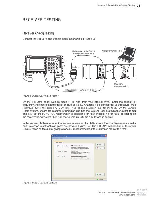
RECEIVER TESTING<br />
Receiver <strong>Analog</strong> Testing<br />
Connect the IFR 2975 <strong>and</strong> <strong>Daniels</strong> <strong>Radio</strong> as shown in Figure 5-3:<br />
Rx Balanced Audio Output<br />
(from pins B26 <strong>and</strong> Z26)<br />
Computer running RSS<br />
ABC<br />
1 2<br />
3<br />
DEF<br />
+<br />
-<br />
.<br />
Audio In<br />
RECEIVER<br />
SYSTEM REGULATOR<br />
POWER<br />
ON<br />
GEN T/R ANT<br />
ON<br />
OFF<br />
SPKR<br />
INT<br />
EXT<br />
DANIELS<br />
ELECTRONICS LTD.<br />
DANIELS<br />
ELECTRONICS LTD.<br />
USB from<br />
Computer to Rx<br />
T/R port from IFR 2975 to RF IN on Rx<br />
Figure 5-3: Receiver <strong>Analog</strong> Testing<br />
On the IFR 2975, recall <strong>Daniels</strong> setup 1 (Rx_Ana) from your internal drive. Enter the correct RF<br />
frequency <strong>and</strong> ensure that the deviation level of the 1.0 KHz tone is set correctly for your receiver (wide<br />
/ narrow). Enter the correct CTCSS tone (if used) <strong>and</strong> deviation level for the tone. On the <strong>Daniels</strong><br />
<strong>Radio</strong> system, ensure the receiver is turned on <strong>and</strong> turn the System Regulator Speaker switch to ON<br />
<strong>and</strong> INT. Set the FUNCTION rotary switch to position 3 for Rx A or position 5 for Rx B (depending on<br />
the receiver being tested), then turn the volume up until the 1 KHz tone is audible.<br />
In the Jumper Settings area of the Service section on the RSS, ensure that the “Subtones on audio<br />
path” selection is set to “Don’t pass” as shown in Figure 5-4. The IFR 2975 will conduct all tests with<br />
CTCSS tones on the audio, giving erroneous measurements, if the Subtones are set to “Pass”.<br />
Figure 5-4: RSS Subtone Settings<br />
MG-001 <strong>Daniels</strong> <strong>MT</strong>-<strong>4E</strong> <strong>Radio</strong> <strong>Systems</strong><br />
www.danelec.com<br />
Maintenance<br />
Guide