MT-4E Analog and P25 Digital Radio Systems - Daniels Electronics
MT-4E Analog and P25 Digital Radio Systems - Daniels Electronics
MT-4E Analog and P25 Digital Radio Systems - Daniels Electronics

Create successful ePaper yourself
Turn your PDF publications into a flip-book with our unique Google optimized e-Paper software.
Chapter 5: <strong>Daniels</strong> <strong>Radio</strong> System Testing 27<br />
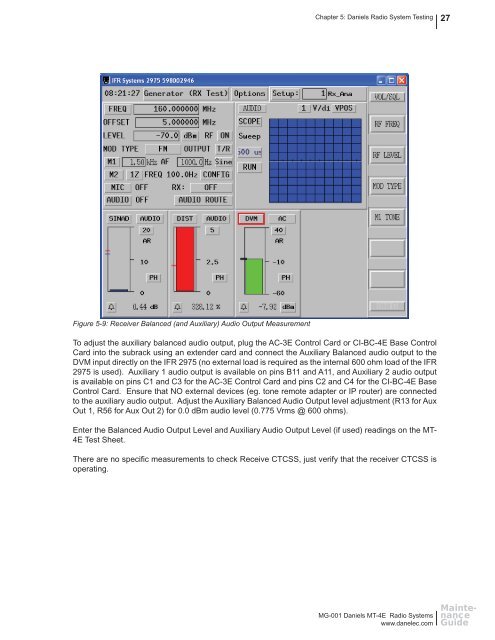
Figure 5-9: Receiver Balanced (<strong>and</strong> Auxiliary) Audio Output Measurement<br />
To adjust the auxiliary balanced audio output, plug the AC-3E Control Card or CI-BC-<strong>4E</strong> Base Control<br />
Card into the subrack using an extender card <strong>and</strong> connect the Auxiliary Balanced audio output to the<br />
DVM input directly on the IFR 2975 (no external load is required as the internal 600 ohm load of the IFR<br />
2975 is used). Auxiliary 1 audio output is available on pins B11 <strong>and</strong> A11, <strong>and</strong> Auxiliary 2 audio output<br />
is available on pins C1 <strong>and</strong> C3 for the AC-3E Control Card <strong>and</strong> pins C2 <strong>and</strong> C4 for the CI-BC-<strong>4E</strong> Base<br />
Control Card. Ensure that NO external devices (eg. tone remote adapter or IP router) are connected<br />
to the auxiliary audio output. Adjust the Auxiliary Balanced Audio Output level adjustment (R13 for Aux<br />
Out 1, R56 for Aux Out 2) for 0.0 dBm audio level (0.775 Vrms @ 600 ohms).<br />
Enter the Balanced Audio Output Level <strong>and</strong> Auxiliary Audio Output Level (if used) readings on the <strong>MT</strong>-<br />
<strong>4E</strong> Test Sheet.<br />
There are no specifi c measurements to check Receive CTCSS, just verify that the receiver CTCSS is<br />
operating.<br />
MG-001 <strong>Daniels</strong> <strong>MT</strong>-<strong>4E</strong> <strong>Radio</strong> <strong>Systems</strong><br />
www.danelec.com<br />
Maintenance<br />
Guide